audio BMW 3 SERIES 2004 E46 CPT8000 Electrical Connectors And Wiring Diagrams Workshop Manual
[x] Cancel search | Manufacturer: BMW, Model Year: 2004, Model line: 3 SERIES, Model: BMW 3 SERIES 2004 E46Pages: 9, PDF Size: 0.84 MB
Page 2 of 9
--------------- BMW CPT8000 Training & Troubleshooting Manual ---------------
Version 2.01 8/29/2001
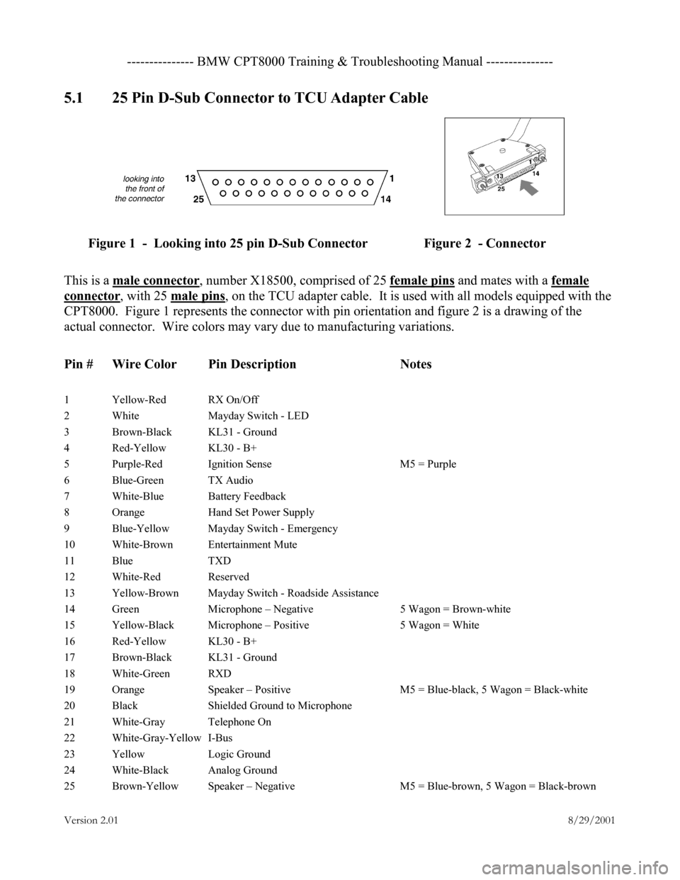
5.1 25 Pin D-Sub Connector to TCU Adapter Cable
Figure 1 - Looking into 25 pin D-Sub Connector Figure 2 - Connector
This is a male connector
, number X18500, comprised of 25 female pins and mates with a female
connector, with 25 male pins, on the TCU adapter cable. It is used with all models equipped with the
CPT8000. Figure 1 represents the connector with pin orientation and figure 2 is a drawing of the
actual connector. Wire colors may vary due to manufacturing variations.
Pin # Wire Color Pin Description Notes
1 Yellow-Red RX On/Off
2 White Mayday Switch - LED
3 Brown-Black KL31 - Ground
4 Red-Yellow KL30 - B+
5 Purple-Red Ignition Sense M5 = Purple
6 Blue-Green TX Audio
7 White-Blue Battery Feedback
8 Orange Hand Set Power Supply
9 Blue-Yellow Mayday Switch - Emergency
10 White-Brown Entertainment Mute
11 Blue TXD
12 White-Red Reserved
13 Yellow-Brown Mayday Switch - Roadside Assistance
14 Green Microphone – Negative 5 Wagon = Brown-white
15 Yellow-Black Microphone – Positive 5 Wagon = White
16 Red-Yellow KL30 - B+
17 Brown-Black KL31 - Ground
18 White-Green RXD
19 Orange Speaker – Positive M5 = Blue-black, 5 Wagon = Black-white
20 Black Shielded Ground to Microphone
21 White-Gray Telephone On
22 White-Gray-Yellow I-Bus
23 Yellow Logic Ground
24 White-Black Analog Ground
25 Brown-Yellow Speaker – Negative M5 = Blue-brown, 5 Wagon = Black-brown
Page 3 of 9
--------------- BMW CPT8000 Training & Troubleshooting Manual ---------------
Version 2.01 8/29/2001
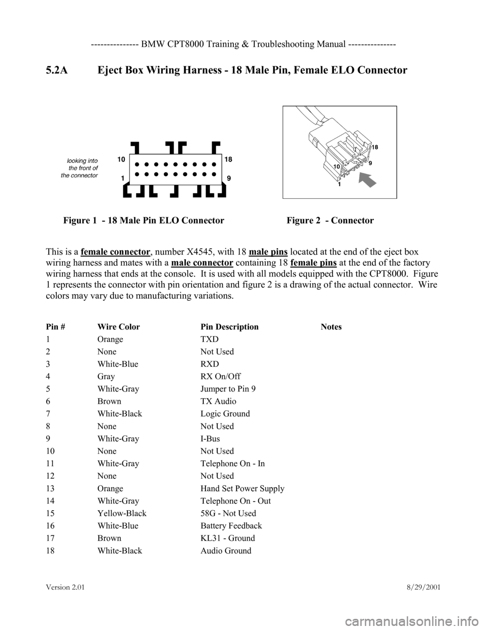
5.2A Eject Box Wiring Harness - 18 Male Pin, Female ELO Connector
Figure 1 - 18 Male Pin ELO Connector Figure 2 - Connector
This is a female connector
, number X4545, with 18 male pins located at the end of the eject box
wiring harness and mates with a male connector
containing 18 female pins at the end of the factory
wiring harness that ends at the console. It is used with all models equipped with the CPT8000. Figure
1 represents the connector with pin orientation and figure 2 is a drawing of the actual connector. Wire
colors may vary due to manufacturing variations.
Pin # Wire Color Pin Description Notes
1 Orange TXD
2 None Not Used
3 White-Blue RXD
4 Gray RX On/Off
5 White-Gray Jumper to Pin 9
6 Brown TX Audio
7 White-Black Logic Ground
8 None Not Used
9 White-Gray I-Bus
10 None Not Used
11 White-Gray Telephone On - In
12 None Not Used
13 Orange Hand Set Power Supply
14 White-Gray Telephone On - Out
15 Yellow-Black 58G - Not Used
16 White-Blue Battery Feedback
17 Brown KL31 - Ground
18 White-Black Audio Ground
Page 4 of 9
--------------- BMW CPT8000 Training & Troubleshooting Manual ---------------
Version 2.01 8/29/2001
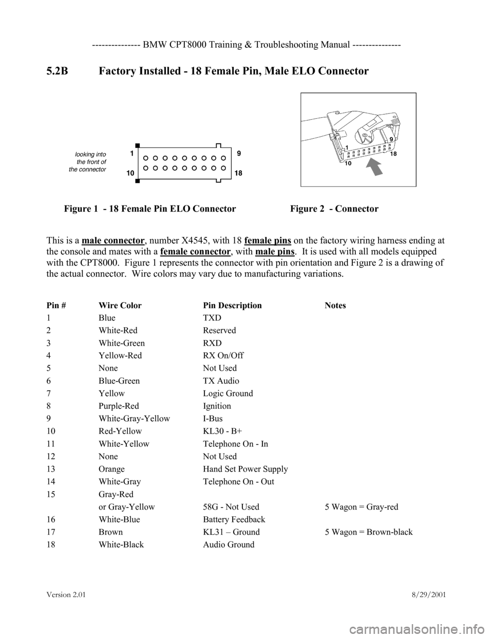
5.2B Factory Installed - 18 Female Pin, Male ELO Connector
Figure 1 - 18 Female Pin ELO Connector Figure 2 - Connector
This is a male connector
, number X4545, with 18 female pins on the factory wiring harness ending at
the console and mates with a female connector
, with male pins. It is used with all models equipped
with the CPT8000. Figure 1 represents the connector with pin orientation and Figure 2 is a drawing of
the actual connector. Wire colors may vary due to manufacturing variations.
Pin # Wire Color Pin Description Notes
1 Blue TXD
2 White-Red Reserved
3 White-Green RXD
4 Yellow-Red RX On/Off
5 None Not Used
6 Blue-Green TX Audio
7 Yellow Logic Ground
8 Purple-Red Ignition
9 White-Gray-Yellow I-Bus
10 Red-Yellow KL30 - B+
11 White-Yellow Telephone On - In
12 None Not Used
13 Orange Hand Set Power Supply
14 White-Gray Telephone On - Out
15 Gray-Red
or Gray-Yellow 58G - Not Used 5 Wagon = Gray-red
16 White-Blue Battery Feedback
17 Brown KL31 – Ground 5 Wagon = Brown-black
18 White-Black Audio Ground
Page 6 of 9
--------------- BMW CPT8000 Training & Troubleshooting Manual ---------------
Version 2.01 8/29/2001
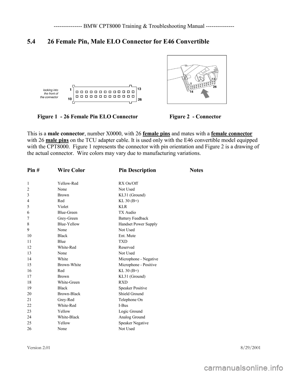
5.4 26 Female Pin, Male ELO Connector for E46 Convertible
Figure 1 - 26 Female Pin ELO Connector Figure 2 - Connector
This is a male connector , number X0000, with 26 female pins and mates with a female connector
with 26 male pins
on the TCU adapter cable. It is used only with the E46 convertible model equipped
with the CPT8000. Figure 1 represents the connector with pin orientation and Figure 2 is a drawing of
the actual connector. Wire colors may vary due to manufacturing variations.
Pin # Wire Color Pin Description Notes
1 Yellow-Red RX On/Off
2 None Not Used
3 Brown KL31 (Ground)
4 Red KL 30 (B+)
5 Violet KLR
6 Blue-Green TX Audio
7 Grey-Green Battery Feedback
8 Blue-Yellow Handset Power Supply
9 None Not Used
10 Black Ent. Mute
11 Blue TXD
12 White-Red Reserved
13 None Not Used
14 White Microphone - Negative
15 Brown-White Microphone - Positive
16 Red KL 30 (B+)
17 Brown KL31 (Ground)
18 White-Green RXD
19 Black Speaker Positive
20 Brown-Black Shield Ground
21 Grey-Red Telephone On
22 White-Red I-Bus
23 Yellow Logic Ground
24 White-Black Analog Ground
25 Yellow Speaker Negative
26 None Not Used
Page 7 of 9
--------------- BMW CPT8000 Training & Troubleshooting Manual ---------------
Version 2.01 8/29/2001
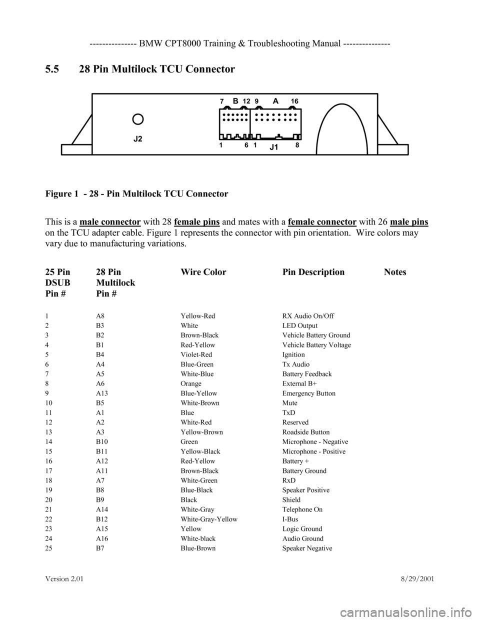
5.5 28 Pin Multilock TCU Connector
Figure 1 - 28 - Pin Multilock TCU Connector
This is a male connector with 28 female pins and mates with a female connector with 26 male pins
on the TCU adapter cable. Figure 1 represents the connector with pin orientation. Wire colors may
vary due to manufacturing variations.
25 Pin 28 Pin Wire Color Pin Description Notes
DSUB Multilock
Pin # Pin #
1 A8 Yellow-Red RX Audio On/Off
2 B3 White LED Output
3 B2 Brown-Black Vehicle Battery Ground
4 B1 Red-Yellow Vehicle Battery Voltage
5 B4 Violet-Red Ignition
6 A4 Blue-Green Tx Audio
7 A5 White-Blue Battery Feedback
8 A6 Orange External B+
9 A13 Blue-Yellow Emergency Button
10 B5 White-Brown Mute
11 A1 Blue TxD
12 A2 White-Red Reserved
13 A3 Yellow-Brown Roadside Button
14 B10 Green Microphone - Negative
15 B11 Yellow-Black Microphone - Positive
16 A12 Red-Yellow Battery +
17 A11 Brown-Black Battery Ground
18 A7 White-Green RxD
19 B8 Blue-Black Speaker Positive
20 B9 Black Shield
21 A14 White-Gray Telephone On
22 B12 White-Gray-Yellow I-Bus
23 A15 Yellow Logic Ground
24 A16 White-black Audio Ground
25 B7 Blue-Brown Speaker Negative
J2 J1
BA161 12
7 16
8
9
Page 8 of 9
---------- BMW CPT8000 Training & Troubleshooting Manual ----------
Versio n 2 .01 8/29/2001
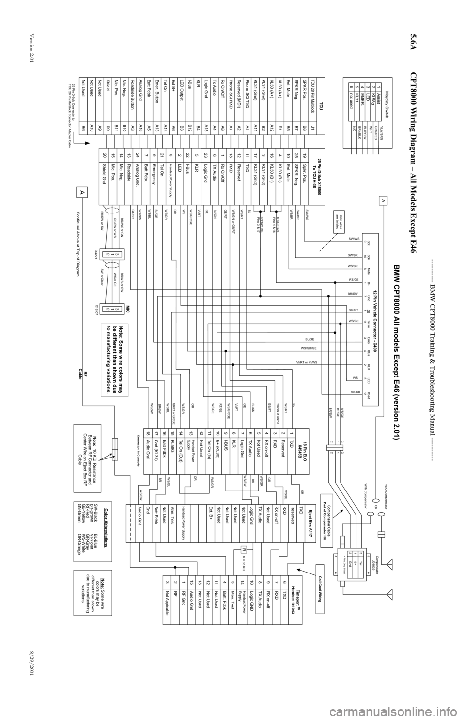
5.6A CPT8000 Wiring Diagram – All Models Except E46
TCU 28 Pin MultilockSPKR Pos.SPKR Neg.Ent. MuteKL30 (A+)KL31 (Gnd)KL30 (A+)KL31 (Gnd)Phone SCI TXDReserved (MDI)Phone SCI RXDTx AudioRx On/OffLogic GndKLRI-BusLED OutputExt B+Tel OnEmer. ButtonBatt FdbkAnalog GndRoadside ButtonMic. Neg.Mic. Pos.ShieldNot UsedNot UsedNot Used
B11B10A3A16B6A10A9B9B3B12B4A15A5A13A14A6A1A11B2A12A4A8A7A2B5B7B8J1B1
AssistKL58gLEDEMER.KL31not used
643215
YLW/BRNGRY/REDWHTBLU/YLWBRN/BLKN/C
Mayday Switch
25 Pin D-Sub Connector to
TCU 28 Pin Multilock Connector Adapter Cable
SPKR. Neg.Spkr. Pos.Ent. MuteKL30 (B+)KL30 (B+)KL31 (Gnd)TXDKL31 (Gnd)ReservedRXDRx On/OffTX AudioLogic GndKLRI-BusLEDHandset Power SupplyEmergencyBatt FdbkAnalog Gnd.RoadsideMic. Neg.Mic. Pos.Shield Gnd
247982015141361181222252341025191117316
Tel On
21
TCU
25 Pin D-Sub X18500
To TCU H-38
RXDTXDRX on-offTX AudioLogic GNDBatt. FdbkMan. TestNot UsedNot UsedNot UsedAudio GndRF GndRFNot Applicable
151312113218976451410
Timeport
TM
Handset 101043
ReservedTXDRXDNot UsedTX AudioLogic GndNot UsedNot UsedNot UsedNot UsedExt. B+Man. TestNot UsedHandset Power SupplyGndAudio GndBatt FdbkEject Box A117
Handset Power
Supply
RX on-off
R
ReservedTXDRXDNot UsedTX AudioLogic GndI-BUSKLRB+ (KL30)Tel On (In)Not UsedTel On (Out)KL58GBatt FdbkHandset Power
SupplyAudio GndGnd (KL31)18 Pin ELOX4545BRX on-offConnector in Console WS/SW
BRWS/BLORWS/GRWS/GRBRWS/SWGR
WS/BLOR
SW /W S
Spk
9
Spk
10Mute
8 B+
1Gnd
7
58
5
Tel on
11
Emer
3IBus
4 KLR
2LED
6 Road
12
12 Pin Vehicle Connector - X400
SW /BR
WS/BR
RT/GE Incl.Pins 4 & 16
BR/SW Incl. Pins 3 & 17
BL
WS/RT
W S/GN or GN/RT
GE/RT
BL/GN
GE
VI/RT
WS/SWWS/GR/GEOR
WS/GR
BL/GE
WS/BL
GE/BR
WS/GR RT/GE BL
WS/RTWS/GN or GN/RTGE
VI/RT
WS/GE
OR
GE/RT
BL/GNWS/BLBR/SW
WS/SWGR/RT or GR/GE
SW/WS
SW/BR
WS/BR RT/GE
BR/SW
GR/RT
WS/GE
BL/GE
WS
VI/RT or VI/WS
WS/GR/GE
GE/BR
WS/GE
RT/GE
BR/SW
A
3
1
2Tel
Gnd
B+14 Pins, Only 3 UsedCompensator
J01039
OR
W /O Compensator
W ith Compensator
Note: 10 K Resistance
Between RF Connector and
Center Wire on Eject Box RF Cable
BR/W S or GNGE/SW or WS
BR/SW or SW
3
1
2
BR/WS or SWWS or GE
SW or Clear
3
1
2
X4221 X18507
A
Continued Above at Top of Diagram
Ω
SW-Black
BR-Brown
RT-Red
GE-Yellow
GN-GreenBL-Blue
VI-Violet
GR-Gray
WS-White
OR-OrangeColor Abbreviations
Note:
Some wire
colors may be
different than shown
due to manufacturing variations
RF
Cable
Coil Cord Wiring
Compensator Cable
Part of Compensator Kit
Spkr wires
are twisted
MIC
WS
3
1
2 3
1
2
R = 33 K
Ω
123456789101112131415161718
WS/GR/GE
BMW CPT8000 All models Except E46 (version 2.01)
Note: Some wire colors may
be different than shown due
to manufacturing variations.
Page 9 of 9
---------- BMW CPT8000 Training & Troubleshooting Manual ----------
Versio n 2 .01 8/29/2001
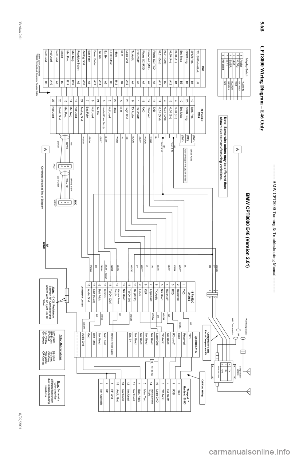
5.6B CPT8000 Wiring Diagram – E46 Only
TCU 28 Pin MultilockSPKR Pos.SPKR Neg.Ent. MuteKL30 (A+)KL31 (Gnd)KL30 (A+)KL31 (Gnd)Phone SCI TXDReserved (MDI)Phone SCI RXDTx AudioRx On/OffLogic GndKLRI-BusLED OutputExt B+Tel OnEmer. ButtonBatt FdbkAnalog GndRoadside ButtonMic. Neg.Mic. Pos.ShieldNot UsedNot UsedNot Used
B11B10A3A16B6A10A9B9B3B12B4A15A5A13A14A6A1A11B2A12A4A8A7A2B5B7B8J1B1
AssistKL58gLEDEMER.KL31not used
643215
YLW /BRNGRY/REDWHTBLU/YLWBRN/BLKN/C
Mayday Switch
26 Pin ELO Connector to
TCU 28 Pin Multilock Connector Adapter Cable
SPKR. Neg.Spkr. Pos.Ent. MuteKL30 (B+)KL30 (B+)KL31 (Gnd)TXDKL31 (Gnd)ReservedRXDRx On/OffTX AudioLogic GndKLRI-BusNot UsedHandset Power SupplyNot UsedBatt FdbkAnalog Gnd.Not UsedMic. Neg.Mic. Pos.Shield Gnd
247982015141361181222252341025191117316
Tel On
21
TCU
26 Pin ELO
X695
RXDTXDRX on-offTX AudioLogic GNDBatt. FdbkMan. TestNot UsedNot UsedNot UsedAudio GndRF GndRFNot Applicable
151312113218976451410
Timeport
TM
Handset 101043
ReservedTXDRXDNot UsedTX AudioLogic GndNot UsedNot UsedNot UsedNot UsedExt. B+Man. TestNot UsedHandset Power SupplyGndAudio GndBatt FdbkEject Box A117
Handset Power
Supply
RX on-off
R
ReservedTXDRXDNot UsedTX AudioLogic GndI-BUSKLRB+ (KL30)Tel On (In)Not UsedTel On (Out)KL58GBatt FdbkHandset Power
SupplyAudio GndGnd (KL31)18 Pin ELOX4545BRX on-offConnector in Console WS/SW
BRWS/BLORWS/GRWS/GRBRWS/SWGR
WS/BLOR
RT
Pins 4 & 16BR
Pins 3 & 17
BL
WS/RT
WS/GN
GE/RT
BL/GN
GE
VI
WS/SWWS/RTBL/GE
GR/RT
GR/GN
GR/RT RT BL
WS/RTWS/GNGE
VI
WS/GE
BL/GE
GE/RT
BL/GNGR/GN BR
WS/SWGR/RT or GR/GEWS/GE
RT
BR
3
1
2 Tel
Gnd
B+14 Pins, Only 3 UsedCompensator
J01039
OR
W /O Compensator
With Compensator
Note: 10 K Resistance
Between RF Connector and
Center Wire on Eject Box RF
Cable
WSBR/W S
BR/SW
3
1
2
BR/W S or SWWS or GE
SW or Clear
3
1
2
X4221 X18507
A
Continued Above at Top of Diagram
Ω
SW-Black
BR-Brown
RT-Red
GE-Yellow
GN-GreenBL-Blue
VI-Violet
GR-Gray
WS-White
OR-OrangeColor Abbreviations
Note:
Some wire
colors may be
different than shown
due to manufacturing
variations
RF
Cable
Coil Cord Wiring
Compensator Cable
Part of Compensator Kit
Spkr wires (pin 19 & 25) are twisted
MIC
3
1
2 3
1
2
R = 33 K
Ω
123456789101112131415161718
WS/RT
BMW CPT8000 E46 (Version 2.01)
Not Used
26
Vehicle Audio
(SW )
(GE)
(SW )
A
Note: Some wire colors may be different than
shown due to manufacturing variations.