lane assist BMW 3 SERIES GRAN COUPE 2014 F34 Owner's Manual
[x] Cancel search | Manufacturer: BMW, Model Year: 2014, Model line: 3 SERIES GRAN COUPE, Model: BMW 3 SERIES GRAN COUPE 2014 F34Pages: 246, PDF Size: 6.49 MB
Page 18 of 246
CockpitVehicle features and options
This chapter describes all standard, country-
specific and optional features offered with the
series. It also describes features that are notnecessarily available in your car, e. g., due to
the selected options or country versions. This
also applies to safety-related functions and
systems.
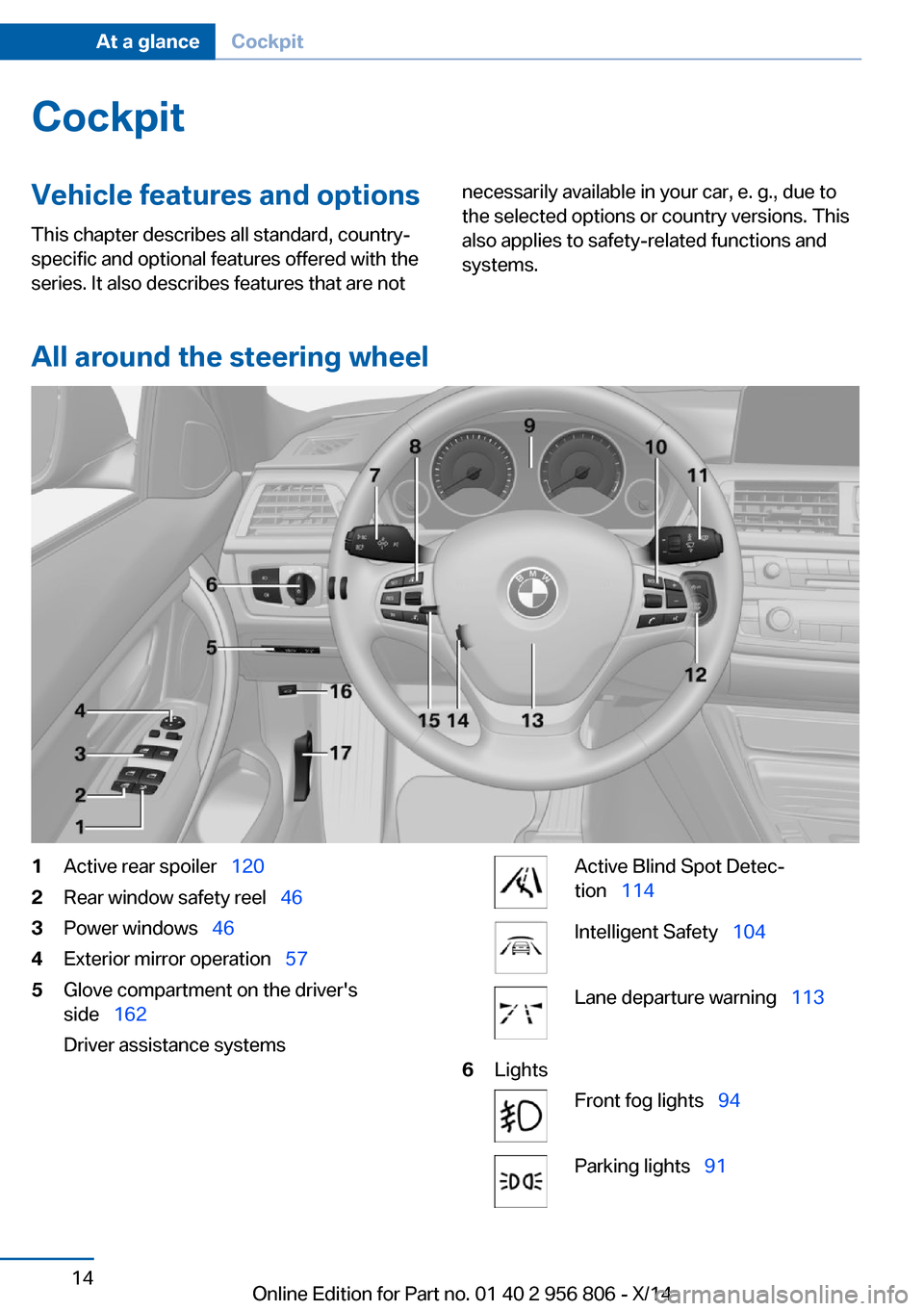
All around the steering wheel
1Active rear spoiler 1202Rear window safety reel 463Power windows 464Exterior mirror operation 575Glove compartment on the driver's
side 162
Driver assistance systemsActive Blind Spot Detec‐
tion 114Intelligent Safety 104Lane departure warning 1136LightsFront fog lights 94Parking lights 91Seite 14At a glanceCockpit14
Online Edition for Part no. 01 40 2 956 806 - X/14
Page 83 of 246
For more information, see Tire Pressure Moni‐
tor, refer to page 99.
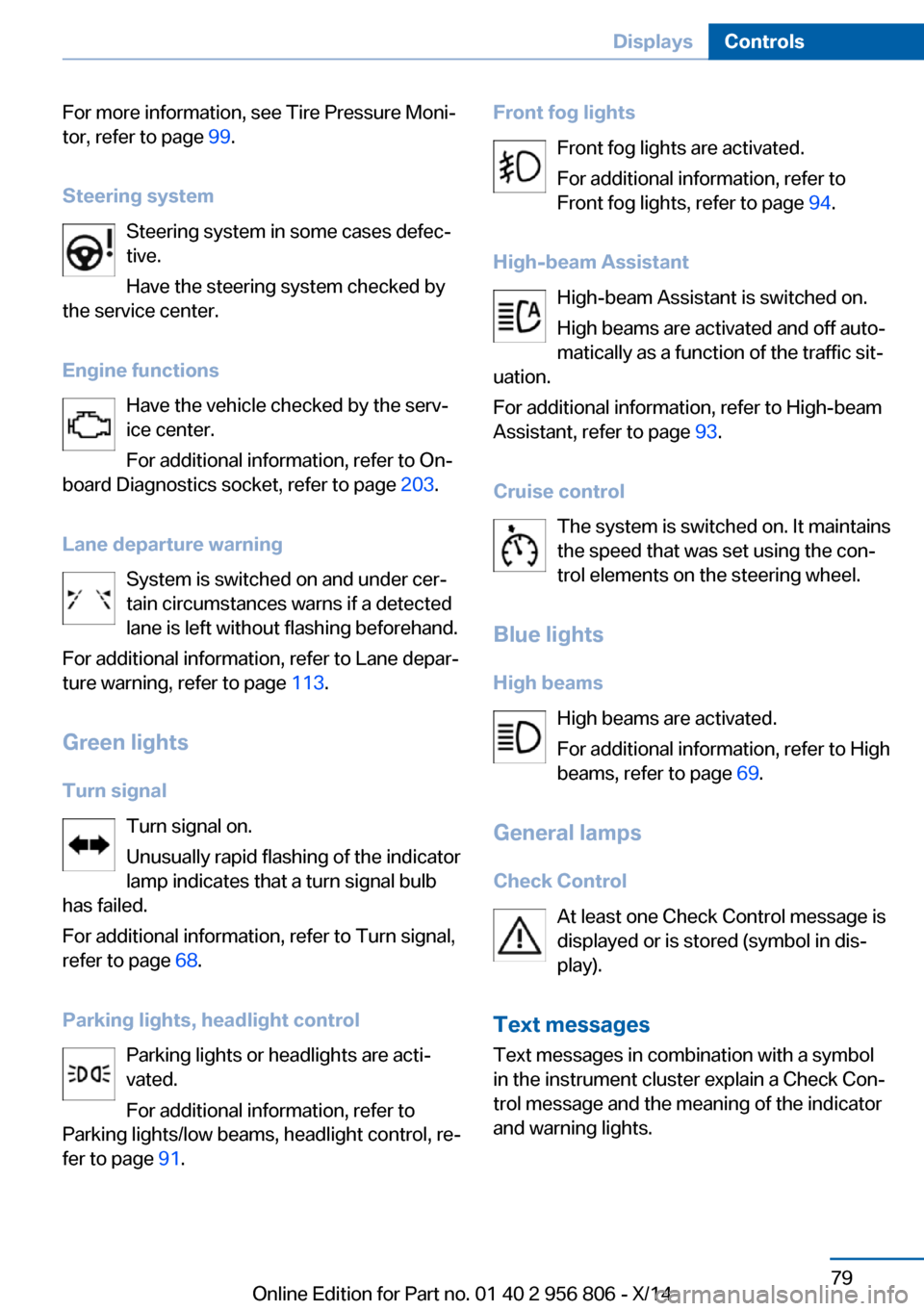
Steering system Steering system in some cases defec‐
tive.
Have the steering system checked by
the service center.
Engine functions Have the vehicle checked by the serv‐ice center.
For additional information, refer to On-
board Diagnostics socket, refer to page 203.
Lane departure warning System is switched on and under cer‐
tain circumstances warns if a detected
lane is left without flashing beforehand.
For additional information, refer to Lane depar‐
ture warning, refer to page 113.
Green lights Turn signal Turn signal on.
Unusually rapid flashing of the indicator
lamp indicates that a turn signal bulb
has failed.
For additional information, refer to Turn signal,
refer to page 68.
Parking lights, headlight control Parking lights or headlights are acti‐
vated.
For additional information, refer to
Parking lights/low beams, headlight control, re‐
fer to page 91.Front fog lights
Front fog lights are activated.
For additional information, refer to
Front fog lights, refer to page 94.
High-beam Assistant High-beam Assistant is switched on.
High beams are activated and off auto‐
matically as a function of the traffic sit‐
uation.
For additional information, refer to High-beam
Assistant, refer to page 93.
Cruise control The system is switched on. It maintains
the speed that was set using the con‐
trol elements on the steering wheel.
Blue lights
High beams High beams are activated.
For additional information, refer to High
beams, refer to page 69.
General lamps
Check Control At least one Check Control message is
displayed or is stored (symbol in dis‐
play).
Text messages Text messages in combination with a symbol
in the instrument cluster explain a Check Con‐
trol message and the meaning of the indicator
and warning lights.Seite 79DisplaysControls79
Online Edition for Part no. 01 40 2 956 806 - X/14
Page 108 of 246
▷When the system has not been initialized.▷When driving on a snowy or slippery road
surface.▷Sporty driving style: spinning traction
wheels, high lateral acceleration (drifting).▷When driving with snow chains.
Actions in the event of a flat tire
Normal tires
1.Identify the damaged tire.
Do this by checking the air pressure in all
four tires.
If the tire inflation pressure in all four tires
is correct, the Flat Tire Monitor may not
have been initialized. In this case, initialize
the system.
If an identification is not possible, please
contact the service center.2.Fix the flat tire.
Run-flat tires
Maximum speed
You may continue driving with a damaged tire
at speeds up to 50 mph/80 km/h.
Continued driving with a flat tire
If continuing to drive with a damaged tire:
1.Avoid sudden braking and steering maneu‐
vers.2.Do not exceed a speed of 50 mph/80 km/h.3.Check the air pressure in all four tires at
the next opportunity.
If the tire inflation pressure in all four tires
is correct, the Flat Tire Monitor may not
have been initialized. In this case, initialize
the system.
Possible driving distance with complete loss of
tire inflation pressure:
The possible driving distance after a loss of tire
inflation pressure depends on cargo load, driv‐
ing style and road conditions.
A vehicle with an average load has a possible
driving range of approx. 50 miles/80 km.
A vehicle with a damaged tire reacts differ‐
ently, e.g., it has reduced lane stability during
braking, a longer braking distance and different
self-steering properties. Adjust your driving
style accordingly. Avoid abrupt steering ma‐
neuvers or driving over obstacles, e.g., curbs,
potholes, etc.
Because the possible driving distance de‐
pends on how the vehicle is used during the
trip, the actual distance may be shorter or lon‐
ger depending on the driving speed, road con‐
ditions, external temperature, cargo load, etc.
Continued driving with a flat tire
Drive moderately and do not exceed a
speed of 50 mph/80 km/h.
Your car handles differently when you lose tire
inflation pressure, e.g., your lane stability is re‐
duced when braking, braking distances are
longer and the self-steering properties will
change.◀
Final tire failure
Vibrations or loud noises while driving
can indicate the final failure of a tire. Reduce
speed and stop; otherwise, pieces of the tire
could come loose and cause an accident. Do
not continue driving and contact your service
center.◀
Intelligent Safety
The concept Intelligent Safety enables central operation of
the driver assistance system.
Depending on how the vehicle is equipped, In‐
telligent Safety consists of one or more sys‐
tems that can help prevent a imminent colli‐
sion. These systems are active automaticallySeite 104ControlsSafety104
Online Edition for Part no. 01 40 2 956 806 - X/14
Page 141 of 246
Switching on/off manuallyPress button.▷On: the LED lights up.▷Off: the LED goes out.
The PDC is shown on the Control Display.
Switching the view via iDrive With PDC activated or Top View switched on:
"Rear view camera"
The rearview camera image is displayed.
Display on the Control Display
Functional requirement
▷The rearview camera is switched on.▷The tailgate is fully closed.
Activating assistance functions
More than one assistance function can be ac‐
tive at the same time.
▷Parking aid lines
"Parking aid lines"
Lanes and turning radius are indicated.
▷Obstacle marking
"Obstacle marking"
Spatially-shaped markings are displayed.
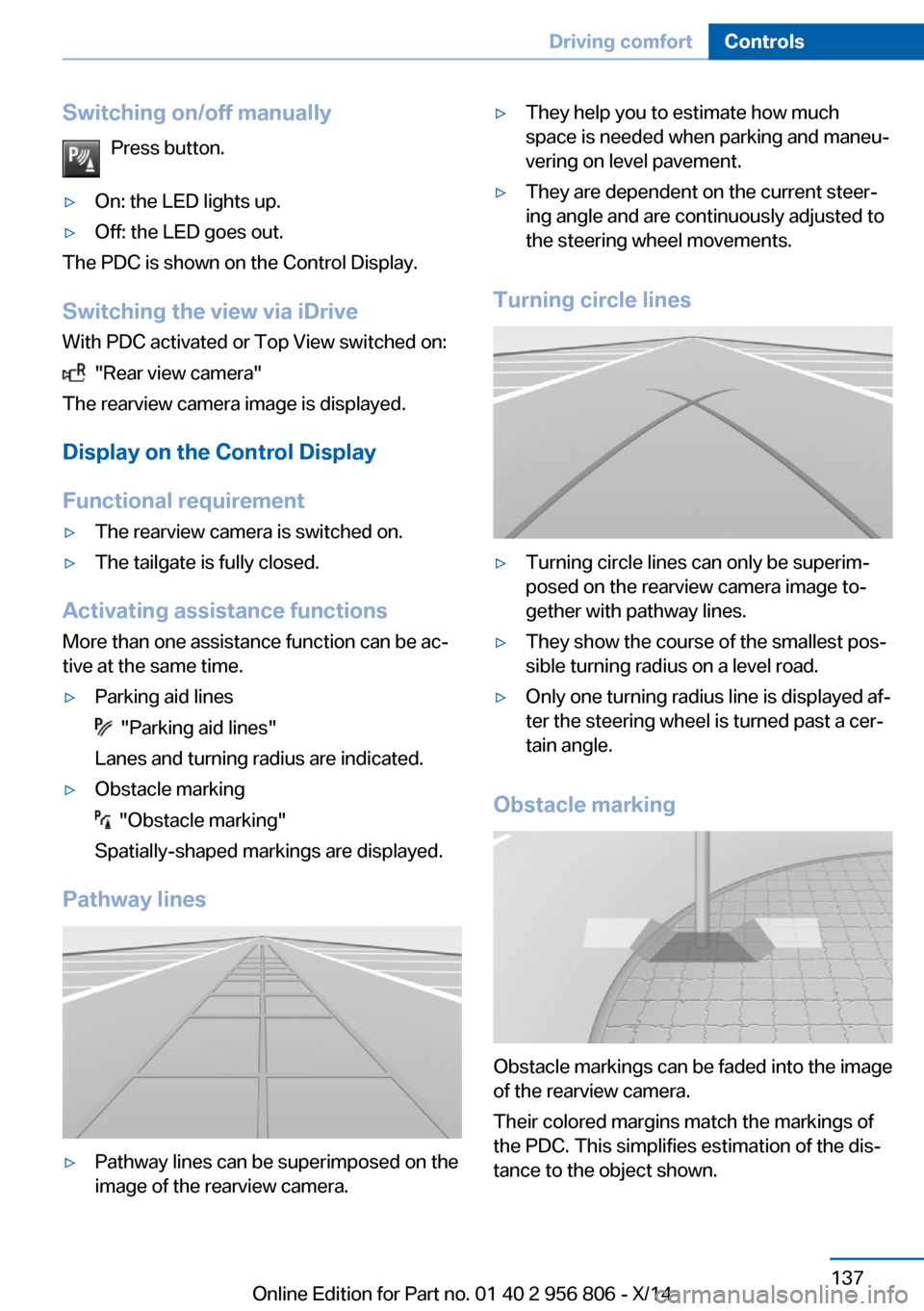
Pathway lines
▷Pathway lines can be superimposed on the
image of the rearview camera.▷They help you to estimate how much
space is needed when parking and maneu‐
vering on level pavement.▷They are dependent on the current steer‐
ing angle and are continuously adjusted to
the steering wheel movements.
Turning circle lines
▷Turning circle lines can only be superim‐
posed on the rearview camera image to‐
gether with pathway lines.▷They show the course of the smallest pos‐
sible turning radius on a level road.▷Only one turning radius line is displayed af‐
ter the steering wheel is turned past a cer‐
tain angle.
Obstacle marking
Obstacle markings can be faded into the image
of the rearview camera.
Their colored margins match the markings of
the PDC. This simplifies estimation of the dis‐
tance to the object shown.
Seite 137Driving comfortControls137
Online Edition for Part no. 01 40 2 956 806 - X/14
Page 145 of 246
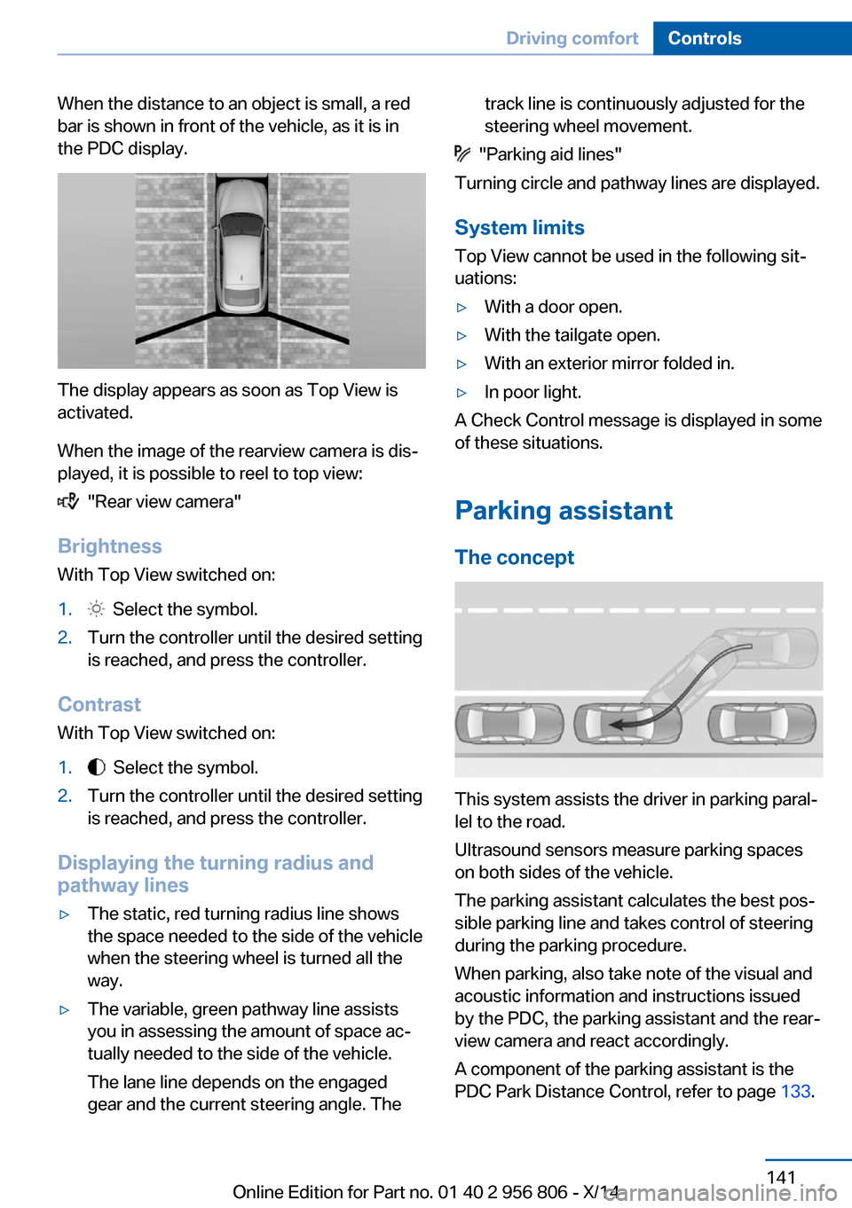
When the distance to an object is small, a red
bar is shown in front of the vehicle, as it is in
the PDC display.
The display appears as soon as Top View is
activated.
When the image of the rearview camera is dis‐
played, it is possible to reel to top view:
"Rear view camera"
Brightness
With Top View switched on:
1. Select the symbol.2.Turn the controller until the desired setting
is reached, and press the controller.
Contrast
With Top View switched on:
1. Select the symbol.2.Turn the controller until the desired setting
is reached, and press the controller.
Displaying the turning radius and
pathway lines
▷The static, red turning radius line shows
the space needed to the side of the vehicle
when the steering wheel is turned all the
way.▷The variable, green pathway line assists
you in assessing the amount of space ac‐
tually needed to the side of the vehicle.
The lane line depends on the engaged
gear and the current steering angle. Thetrack line is continuously adjusted for the
steering wheel movement.
"Parking aid lines"
Turning circle and pathway lines are displayed.
System limits
Top View cannot be used in the following sit‐
uations:
▷With a door open.▷With the tailgate open.▷With an exterior mirror folded in.▷In poor light.
A Check Control message is displayed in some
of these situations.
Parking assistant The concept
This system assists the driver in parking paral‐
lel to the road.
Ultrasound sensors measure parking spaces
on both sides of the vehicle.
The parking assistant calculates the best pos‐
sible parking line and takes control of steering
during the parking procedure.
When parking, also take note of the visual and
acoustic information and instructions issued
by the PDC, the parking assistant and the rear‐
view camera and react accordingly.
A component of the parking assistant is the
PDC Park Distance Control, refer to page 133.
Seite 141Driving comfortControls141
Online Edition for Part no. 01 40 2 956 806 - X/14
Page 240 of 246
Horn 14
Hot exhaust system 168
HUD Head-up Display 89
Hydroplaning 169
I Ice warning, see External temperature warning 81
Icy roads, see External tem‐ perature warning 81
Identification marks, tires 191
Identification number, see ve‐ hicle identification num‐
ber 9
iDrive 18
Ignition key, refer to Remote control 34
Ignition off 64
Ignition on 64
Indication of a flat tire 100 , 103
Indicator and alarm lamps, see Check Control 77
Indicator lamp, see Check Control 77
Individual air distribu‐ tion 147, 150
Individual settings, refer to Personal Profile 35
Inflation pressure, tires 188
Inflation pressure warning FTM, tires 103
Info display, refer to Com‐ puter 85
Initialize, Tire Pressure Moni‐ tor TPM 100
Initializing, Flat Tire Monitor FTM 103
Instrument cluster 76
Instrument cluster, electronic displays 76
Instrument lighting 94
Integrated key 34
Integrated Owner's Manual in the vehicle 29 Intelligent Emergency Re‐
quest 216
Intelligent Safety 104
Intensity, AUTO pro‐ gram 149
Interior equipment 153
Interior lights 94
Interior lights via remote con‐ trol 37
Interior motion sensor 46
Interior rearview mirror, auto‐ matic dimming feature 58
Interior rearview mirror, com‐ pass 155
Interior rearview mirror, man‐ ually dimmable 58
Interval display, service re‐ quirements 82
J Jacking points for the vehicle jack 213
Joystick, Steptronic transmis‐ sion 72
Jump-starting 217
K
Key/remote control 34
Keyless Go, refer to Comfort Access 41
Key Memory, refer to Per‐ sonal Profile 35
Kickdown, Steptronic trans‐ mission 72
Knee airbag 97
L Lamp replacement 205
Lamp replacement, front 206
Lamp replacement, rear 211
Lane departure warning 113
Lane margin, warning 113 Language on Control Dis‐
play 88
Lashing eyes, securing cargo 172
LATCH child restraint sys‐ tem 62
Launch Control 74
Leather, care 222
LEDs, light-emitting di‐ odes 206
Length, vehicle 228
Letters and numbers, enter‐ ing 25
Light alloy wheels, care 223
Light control 92
Light-emitting diodes, LEDs 206
Lighter 157
Lighting 91
Lighting via remote con‐ trol 37
Light reel 91
Lights 91
Lights and bulbs 205
Load 172
Loading 171
Loading position 161
Lock, door 38
Locking/unlocking via door lock 38
Locking/unlocking with re‐ mote control 37
Locking, automatic 44
Locking, settings 44
Lock, power window 47
Locks, doors, and win‐ dows 63
Low beams 91
Low beams, automatic, refer to High-beam Assistant 93
Lower back support 52
Luggage rack, see Roof- mounted luggage rack 173
Lumbar support 52 Seite 236ReferenceEverything from A to Z236
Online Edition for Part no. 01 40 2 956 806 - X/14