turn signal mirror BMW 3 SERIES GRAN TURISMO 2016 F34 Owner's Manual
[x] Cancel search | Manufacturer: BMW, Model Year: 2016, Model line: 3 SERIES GRAN TURISMO, Model: BMW 3 SERIES GRAN TURISMO 2016 F34Pages: 251, PDF Size: 5.42 MB
Page 73 of 251
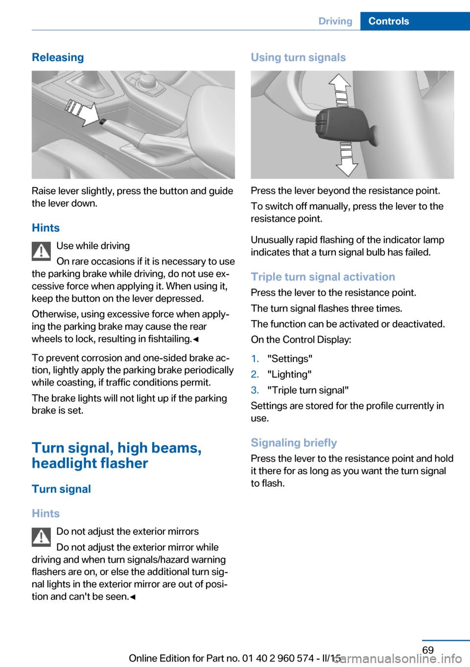
Releasing
Raise lever slightly, press the button and guide
the lever down.
Hints Use while driving
On rare occasions if it is necessary to use
the parking brake while driving, do not use ex‐
cessive force when applying it. When using it,
keep the button on the lever depressed.
Otherwise, using excessive force when apply‐
ing the parking brake may cause the rear
wheels to lock, resulting in fishtailing.◀
To prevent corrosion and one-sided brake ac‐
tion, lightly apply the parking brake periodically
while coasting, if traffic conditions permit.
The brake lights will not light up if the parking
brake is set.
Turn signal, high beams,
headlight flasher
Turn signal
Hints Do not adjust the exterior mirrors
Do not adjust the exterior mirror while
driving and when turn signals/hazard warning
flashers are on, or else the additional turn sig‐
nal lights in the exterior mirror are out of posi‐
tion and can't be seen.◀
Using turn signals
Press the lever beyond the resistance point.
To switch off manually, press the lever to the
resistance point.
Unusually rapid flashing of the indicator lamp
indicates that a turn signal bulb has failed.
Triple turn signal activation Press the lever to the resistance point.
The turn signal flashes three times.
The function can be activated or deactivated.
On the Control Display:
1."Settings"2."Lighting"3."Triple turn signal"
Settings are stored for the profile currently in
use.
Signaling briefly
Press the lever to the resistance point and hold
it there for as long as you want the turn signal
to flash.
Seite 69DrivingControls69
Online Edition for Part no. 01 40 2 960 574 - II/15
Page 98 of 251
In tight curves, e.g., on mountainous roads or
when turning, one of the two front fog lights is
switched on as a turning lamp. As a result the
inside of the curve is better lighted.
ActivatingPosition of switch
with the ignition
switched on.
To avoid blinding oncoming traffic, the Adap‐
tive Light Control does not swivel to the driv‐
er's side when the vehicle is at a standstill.
The turning lights are automatically switched
on depending on the steering angle or the use
of turn signals.
When driving in reverse, the turning lights may
be automatically switched on regardless of the
steering angle.
Malfunction A Check Control message is displayed.
Adaptive Light Control is malfunctioning or has
failed. Have the system checked as soon as
possible.
High-beam Assistant
The concept When the low beams are activated, this system
automatically switches the high beams on and
off or suppresses the light in the areas that
blind oncoming traffic. The procedure is con‐
trolled by a camera on the front of the interior
rearview mirror. The assistant ensures that the
high beams are activated whenever the traffic
situation allows. The driver can intervene at
any time and switch the high beams non and
off as usual.
Note Personal responsibility
The High-beam Assistant cannot serve
as a substitute for the driver's personal judg‐
ment of when to use the high beams. There‐
fore, manually reel off the high beams in situa‐
tions where required to avoid a safety risk.◀
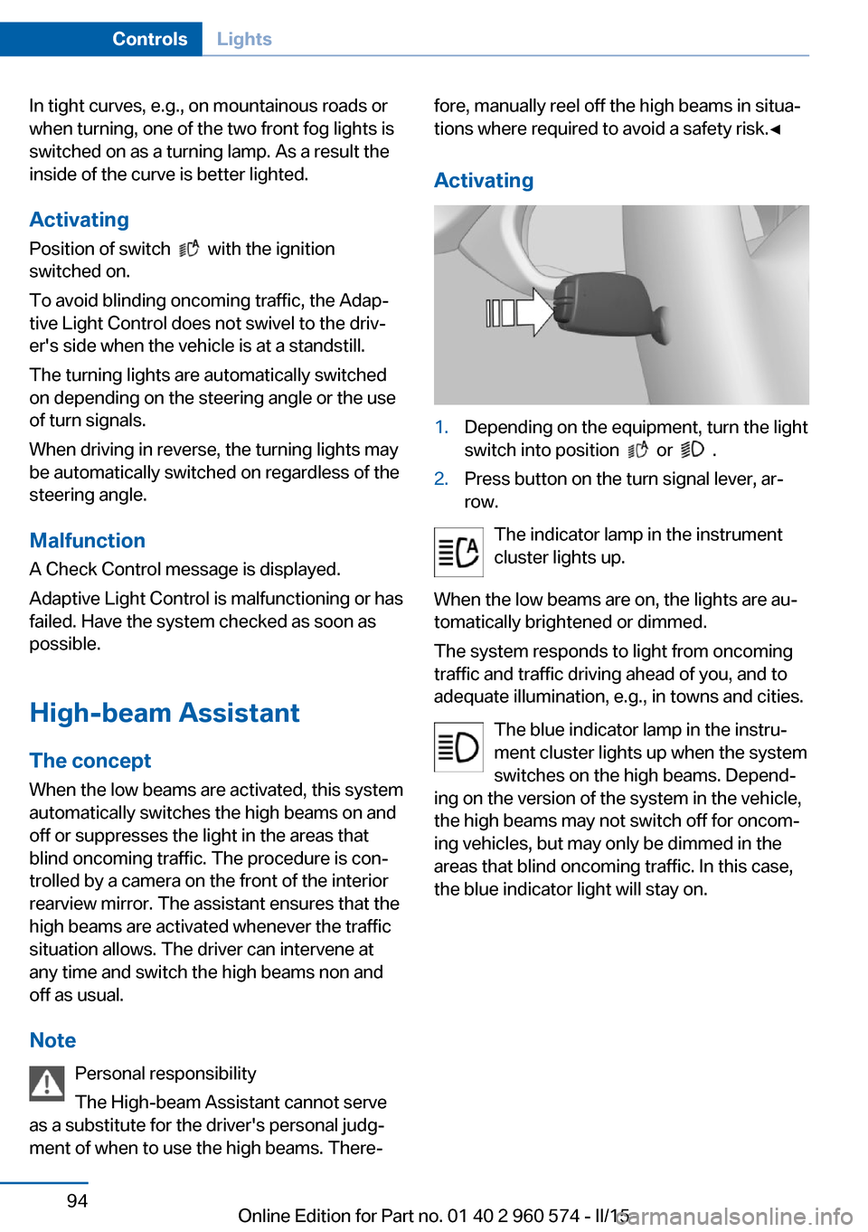
Activating1.Depending on the equipment, turn the light
switch into position
or .
2.Press button on the turn signal lever, ar‐
row.
The indicator lamp in the instrument
cluster lights up.
When the low beams are on, the lights are au‐
tomatically brightened or dimmed.
The system responds to light from oncoming
traffic and traffic driving ahead of you, and to
adequate illumination, e.g., in towns and cities.
The blue indicator lamp in the instru‐
ment cluster lights up when the system
switches on the high beams. Depend‐
ing on the version of the system in the vehicle, the high beams may not switch off for oncom‐
ing vehicles, but may only be dimmed in the
areas that blind oncoming traffic. In this case,
the blue indicator light will stay on.
Seite 94ControlsLights94
Online Edition for Part no. 01 40 2 960 574 - II/15
Page 99 of 251
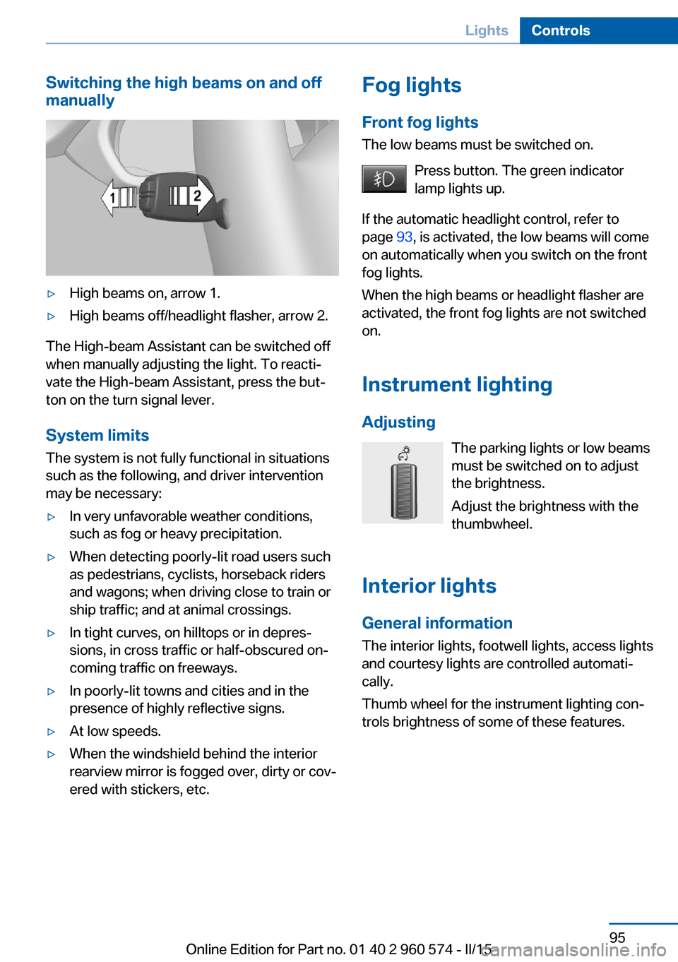
Switching the high beams on and off
manually▷High beams on, arrow 1.▷High beams off/headlight flasher, arrow 2.
The High-beam Assistant can be switched off
when manually adjusting the light. To reacti‐
vate the High-beam Assistant, press the but‐
ton on the turn signal lever.
System limits
The system is not fully functional in situations such as the following, and driver intervention
may be necessary:
▷In very unfavorable weather conditions,
such as fog or heavy precipitation.▷When detecting poorly-lit road users such
as pedestrians, cyclists, horseback riders
and wagons; when driving close to train or
ship traffic; and at animal crossings.▷In tight curves, on hilltops or in depres‐
sions, in cross traffic or half-obscured on‐
coming traffic on freeways.▷In poorly-lit towns and cities and in the
presence of highly reflective signs.▷At low speeds.▷When the windshield behind the interior
rearview mirror is fogged over, dirty or cov‐
ered with stickers, etc.Fog lights
Front fog lights
The low beams must be switched on.
Press button. The green indicator
lamp lights up.
If the automatic headlight control, refer to
page 93, is activated, the low beams will come
on automatically when you switch on the front
fog lights.
When the high beams or headlight flasher are
activated, the front fog lights are not switched
on.
Instrument lighting Adjusting The parking lights or low beams
must be switched on to adjust
the brightness.
Adjust the brightness with the
thumbwheel.
Interior lights
General information The interior lights, footwell lights, access lights
and courtesy lights are controlled automati‐
cally.
Thumb wheel for the instrument lighting con‐
trols brightness of some of these features.Seite 95LightsControls95
Online Edition for Part no. 01 40 2 960 574 - II/15
Page 119 of 251
When switching on the system below this
speed, a message is displayed in the instru‐
ment cluster.
The steering wheel begins vibrating gently in
the event of warnings. The time of the warning
may vary depending on the current driving sit‐
uation.
The system does not provide a warning if the
turn signal is set before leaving the lane.
Hints Personal responsibility
The system cannot serve as a substitute
for the driver's personal judgment of the
course of the road and the traffic situation.
In the event of a warning, do not jerk the steer‐
ing wheel, as you may lose control of the vehi‐
cle.◀
At a glance
Button in the vehicle
Lane departure warning
Camera
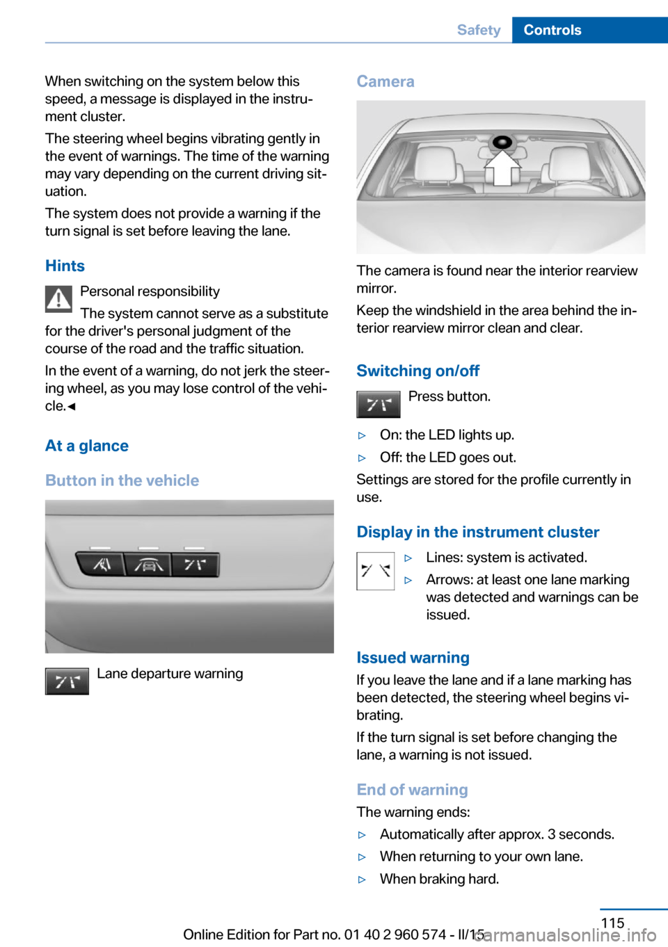
The camera is found near the interior rearview
mirror.
Keep the windshield in the area behind the in‐
terior rearview mirror clean and clear.
Switching on/off Press button.
▷On: the LED lights up.▷Off: the LED goes out.
Settings are stored for the profile currently in
use.
Display in the instrument cluster
▷Lines: system is activated.▷Arrows: at least one lane marking
was detected and warnings can be
issued.
Issued warning
If you leave the lane and if a lane marking has
been detected, the steering wheel begins vi‐
brating.
If the turn signal is set before changing the
lane, a warning is not issued.
End of warning
The warning ends:
▷Automatically after approx. 3 seconds.▷When returning to your own lane.▷When braking hard.Seite 115SafetyControls115
Online Edition for Part no. 01 40 2 960 574 - II/15
Page 120 of 251
▷When using the turn signal.
System limits
The system may not be fully functional in the
following situations:
▷In heavy fog, rain or snowfall.▷In the event of missing, worn, poorly visi‐
ble, merging, diverging, or multiple lane
markings such as in construction areas.▷When lane markings are covered in snow,
ice, dirt or water.▷In tight curves or on narrow lanes.▷When the lane markings are covered by
objects.▷When driving very close to the vehicle in
front of you.▷When driving toward bright lights.▷When the windshield in front of the interior
rearview mirror is fogged over, dirty or cov‐
ered with stickers, etc.▷During calibration of the camera immedi‐
ately after vehicle shipment.
Active Blind Spot Detection
The concept
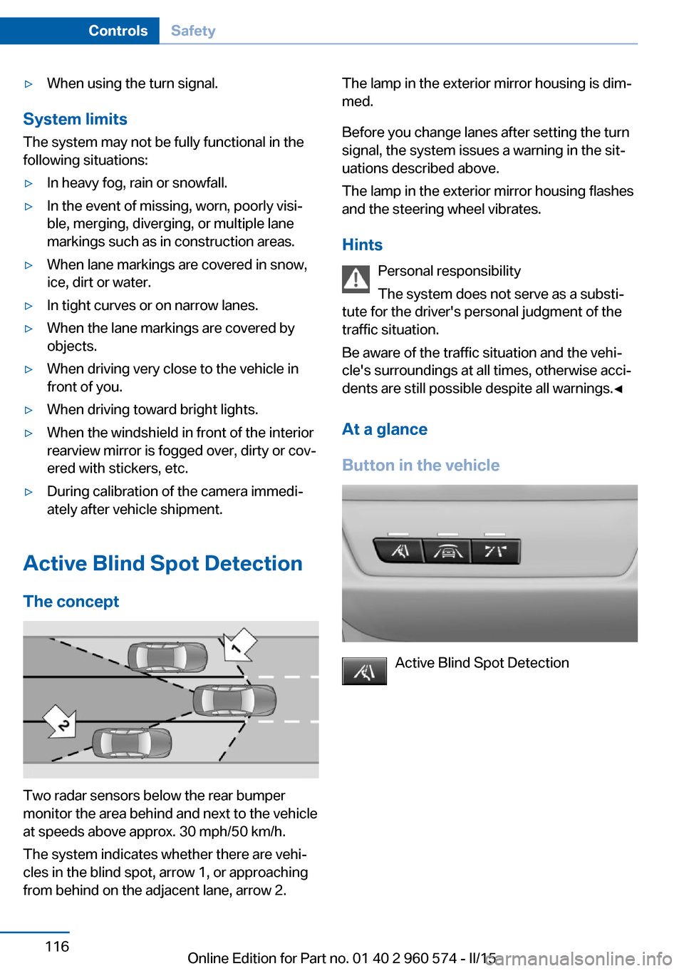
Two radar sensors below the rear bumper
monitor the area behind and next to the vehicle
at speeds above approx. 30 mph/50 km/h.
The system indicates whether there are vehi‐
cles in the blind spot, arrow 1, or approaching
from behind on the adjacent lane, arrow 2.
The lamp in the exterior mirror housing is dim‐
med.
Before you change lanes after setting the turn
signal, the system issues a warning in the sit‐
uations described above.
The lamp in the exterior mirror housing flashes
and the steering wheel vibrates.
Hints Personal responsibility
The system does not serve as a substi‐
tute for the driver's personal judgment of the
traffic situation.
Be aware of the traffic situation and the vehi‐
cle's surroundings at all times, otherwise acci‐
dents are still possible despite all warnings.◀
At a glance
Button in the vehicle
Active Blind Spot Detection
Seite 116ControlsSafety116
Online Edition for Part no. 01 40 2 960 574 - II/15
Page 121 of 251
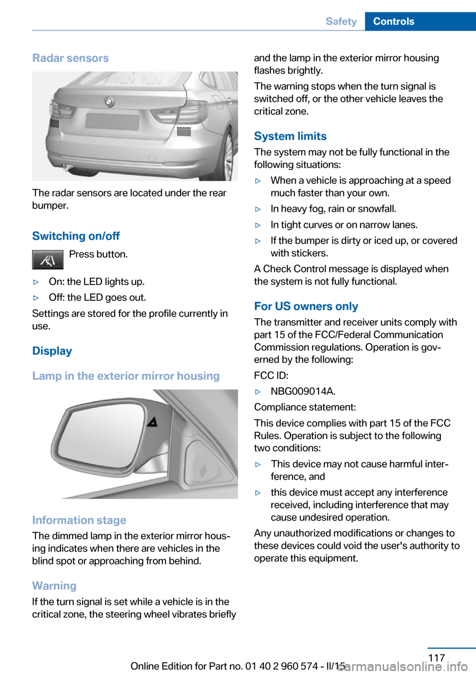
Radar sensors
The radar sensors are located under the rear
bumper.
Switching on/off Press button.
▷On: the LED lights up.▷Off: the LED goes out.
Settings are stored for the profile currently in
use.
Display
Lamp in the exterior mirror housing
Information stage
The dimmed lamp in the exterior mirror hous‐
ing indicates when there are vehicles in the
blind spot or approaching from behind.
Warning If the turn signal is set while a vehicle is in the
critical zone, the steering wheel vibrates briefly
and the lamp in the exterior mirror housing
flashes brightly.
The warning stops when the turn signal is
switched off, or the other vehicle leaves the
critical zone.
System limits
The system may not be fully functional in the
following situations:▷When a vehicle is approaching at a speed
much faster than your own.▷In heavy fog, rain or snowfall.▷In tight curves or on narrow lanes.▷If the bumper is dirty or iced up, or covered
with stickers.
A Check Control message is displayed when
the system is not fully functional.
For US owners only The transmitter and receiver units comply with
part 15 of the FCC/Federal Communication
Commission regulations. Operation is gov‐
erned by the following:
FCC ID:
▷NBG009014A.
Compliance statement:
This device complies with part 15 of the FCC
Rules. Operation is subject to the following
two conditions:
▷This device may not cause harmful inter‐
ference, and▷this device must accept any interference
received, including interference that may
cause undesired operation.
Any unauthorized modifications or changes to
these devices could void the user's authority to
operate this equipment.
Seite 117SafetyControls117
Online Edition for Part no. 01 40 2 960 574 - II/15
Page 219 of 251
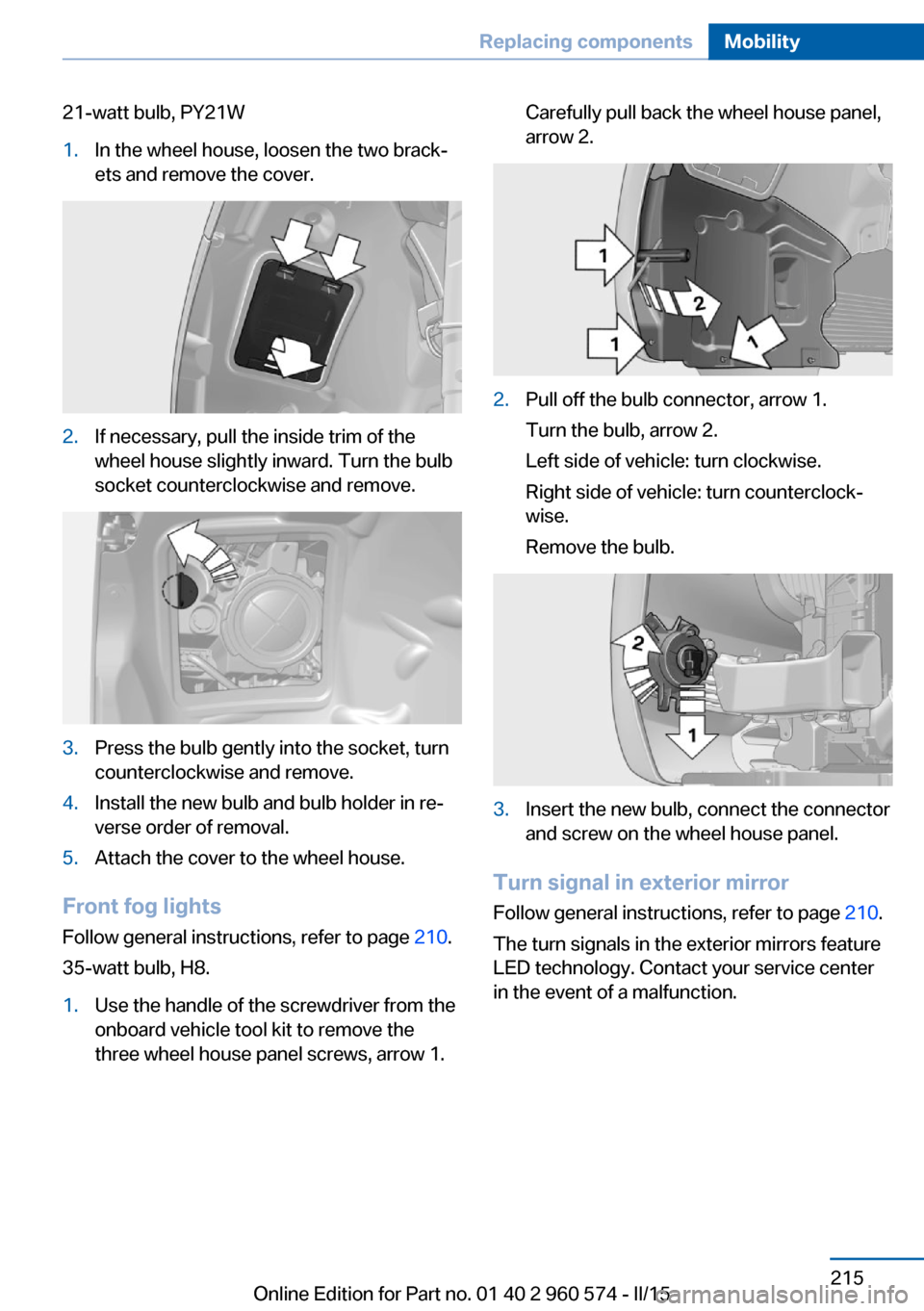
21-watt bulb, PY21W1.In the wheel house, loosen the two brack‐
ets and remove the cover.2.If necessary, pull the inside trim of the
wheel house slightly inward. Turn the bulb
socket counterclockwise and remove.3.Press the bulb gently into the socket, turn
counterclockwise and remove.4.Install the new bulb and bulb holder in re‐
verse order of removal.5.Attach the cover to the wheel house.
Front fog lights
Follow general instructions, refer to page 210.
35-watt bulb, H8.
1.Use the handle of the screwdriver from the
onboard vehicle tool kit to remove the
three wheel house panel screws, arrow 1.Carefully pull back the wheel house panel,
arrow 2.2.Pull off the bulb connector, arrow 1.
Turn the bulb, arrow 2.
Left side of vehicle: turn clockwise.
Right side of vehicle: turn counterclock‐
wise.
Remove the bulb.3.Insert the new bulb, connect the connector
and screw on the wheel house panel.
Turn signal in exterior mirror
Follow general instructions, refer to page 210.
The turn signals in the exterior mirrors feature
LED technology. Contact your service center
in the event of a malfunction.
Seite 215Replacing componentsMobility215
Online Edition for Part no. 01 40 2 960 574 - II/15
Page 242 of 251
tertainment and Communi‐
cation
ConnectedDrive Services
Connecting electrical devi‐ ces 158
Continued driving with a flat tire 102 , 105
Control Display 18
Control Display, settings 89
Controller 18, 19
Control systems, driving sta‐ bility 119
Convenient opening with the remote control 37
Coolant 207
Coolant level 207
Coolant temperature 82
Cooling function 148, 151
Cooling, maximum 150
Cooling system 207
Cornering light 93
Corrosion on brake discs 172
Cosmetic mirror 158
Courtesy lamps during un‐ locking 37
Courtesy lamps with the vehi‐ cle locked 38
Cruise control 132
Cruise control, active with Stop & Go 126
Cruising range 82
Cupholders 165
Current fuel consumption 83
D
Damage, tires 195
Damping control, dy‐ namic 121
Data, technical 232
Date 82
Daytime running lights 93
Defrosting, refer to defrosting the windows 148
Defrosting, refer to Windows, defrosting 152 Defrosting the windows 148
Dehumidifying, air 148, 151
Deleting personal data 25
Deletion of personal data 25
Destination distance 87
Digital clock 82
Digital compass 156
Dimensions 232
Dimmable exterior mirrors 59
Dimmable interior rearview mirror 59
Direction indicator, refer to Turn signals 69
Display, electronic, instru‐ ment cluster 77
Display in windshield 90
Display lighting, refer to In‐ strument lighting 95
Displays, cleaning 229
Disposal, coolant 207
Disposal, vehicle battery 219
Distance control, refer to PDC 134
Distance to destination 87
Divided screen view, split screen 23
Door lock 39
Door lock, refer to Remote control 34
Drive-off assistant 124
Drive-off assistant, refer to DSC 119
Driver assistance, refer to In‐ telligent Safety 106
Driving Assistant, refer to In‐ telligent Safety 106
Driving Dynamics Con‐ trol 122
Driving instructions, break- in 170
Driving mode 122
Driving notes, general 170
Driving stability control sys‐ tems 119
Driving style analysis 181
Driving tips 170 DSC Dynamic Stability Con‐
trol 119
DTC Dynamic Traction Con‐ trol 120
Dynamic Damping Con‐ trol 121
Dynamic Stability Control DSC 119
Dynamic Traction Control DTC 120
E
ECO PRO 177
ECO PRO, bonus range 178
ECO PRO display 177
ECO PRO driving mode 177
ECO PRO driving style analy‐ sis 181
ECO PRO mode 177
ECO PRO Tip - driving in‐ struction 179
EfficientDynamics 179
Electronic displays, instru‐ ment cluster 77
Electronic oil measure‐ ment 204
Electronic Stability Program ESP, refer to DSC 119
Emergency detection, remote control 35
Emergency release, fuel filler flap 186
Emergency Request 221
Emergency start function, en‐ gine start 35
Emergency unlocking, tail‐ gate 42
Emergency unlocking, trans‐ mission lock 75
Energy Control 83
Energy recovery 83
Engine, automatic Start/Stop function 67
Engine, automatic switch- off 67 Seite 238ReferenceEverything from A to Z238
Online Edition for Part no. 01 40 2 960 574 - II/15
Page 246 of 251
Outside air, refer to Auto‐matic recirculated-air con‐
trol 151
Overheating of engine, refer to Coolant temperature 82
P Paint, vehicle 227
Panoramic glass sunroof 49
Parallel parking assistant 142
Park Distance Control PDC 134
Parked-car ventilation 153
Parked vehicle, condensa‐ tion 172
Parking aid, refer to PDC 134
Parking assistant 142
Parking brake 68
Parking lights 92
Parts and accessories 7
Passenger side mirror, tilting downward 58
Pathway lines, rearview cam‐ era 138
PDC Park Distance Con‐ trol 134
Pedestrian warning with city braking function 112
Personal Profile 35
Personal Profile, exporting profiles 36
Personal Profile, importing profiles 37
Pinch protection system, glass sunroof 50
Pinch protection system, win‐ dows 48
Plastic, care 228
Power failure 219
Power windows 47
Pressure, tire air pres‐ sure 190
Pressure warning FTM, tires 104 Profile, refer to Personal Pro‐
file 35
Programmable memory but‐ tons, iDrive 24
Protective function, glass sunroof 50
Protective function, win‐ dows 48
Push-and-turn switch, refer to Controller 18, 19
R Radiator fluid 207
Radio-operated key, refer to Remote control 34
Radio ready state 65
Radio, see user's manual for Navigation, Entertainment
and Communication
Rain sensor 71
Rear lights 218
Rear seat backrest, adjust‐ ing 162
Rear seat backrest tilt 162
Rear socket 159
Rear spoiler, active 121
Rear turn signal, bulb replace‐ ment 216
Rearview camera 137
Rearview mirror 58
Rear window de‐ froster 148, 151
Recirculated-air filter 152
Recirculated-air mode 148, 151
Recommended fuel grade 188
Recommended tire brands 196
Refueling 186
Remaining range 82
Remote control/key 34
Remote control, malfunc‐ tion 38 Remote control, univer‐
sal 154
Replacement fuse 219
Replacing parts 210
Replacing wheels/tires 196
Reporting safety defects 9
RES button 129
RES button, see Active Cruise Control, ACC 126
RES button, see Cruise con‐ trol 132
Reserve warning, refer to Range 82
Reset, Tire Pressure Monitor TPM 101
Retaining straps, securing cargo 174
Retreaded tires 196
Roadside parking lights 93
RON recommended fuel grade 188
Roofliner 17
Roof load lidacity 233
Roof-mounted luggage rack 175
Rope for tow-starting/ towing 224
RSC Run Flat System Com‐ ponent, refer to Run-flat
tires 197
Rubber components, care 228
Run-flat tires 197
S Safe braking 171
Safety 7
Safety belt reminder for driv‐ er's seat and front passen‐
ger seat 55
Safety belts 54
Safety belts, care 229
Safety switch, windows 48
Safety systems, airbags 97
Saving fuel 176 Seite 242ReferenceEverything from A to Z242
Online Edition for Part no. 01 40 2 960 574 - II/15
Page 247 of 251
Screen, refer to Control Dis‐play 18
Screwdriver, see Onboard ve‐ hicle tool kit 210
Screw thread, see screw thread for tow fitting, screw
thread for tow fitting 225
Sealant 197
Seat and mirror memory 57
Seat belts, refer to Safety belts 54
Seat heating, front 54
Seat heating, rear 54
Seating position for chil‐ dren 61
Seats 51
Selection list in instrument cluster 86
Selector lever, Steptronic transmission 73
Sensors, care 229
Service and warranty 8
Service requirements, Condi‐ tion Based Service
CBS 208
Service requirements, dis‐ play 83
Services, ConnectedDrive
Servotronic 125
SET button, see Active Cruise Control, ACC 126
SET button, see Cruise con‐ trol 132
Settings, locking/unlock‐ ing 45
Settings on Control Dis‐ play 89
Settings, storing for seat, mir‐ ror 57
Shift paddles on the steering wheel 74
Side airbags 97
Side View 139
Signaling, horn 14
Signals when unlocking 45
Sitting safely 51 Size 232
Slide/tilt glass roof 49
Smallest turning radius 232
Snow chains 201
Socket 158
Socket, OBD Onboard Diag‐ nostics 209
SOS button 221
Spare fuse 219
Specified engine oil types 206
Speed, average 87
Speed limit detection, on- board computer 87
Speed limiter, display 84
Speed Limit Information 84
Speed warning 88
Split screen 23
SPORT+ - program, Dynamic Driving Control 123
Sport displays, torque dis‐ play, performance dis‐
play 88
SPORT program, Dynamic Driving Control 123
Sport program, transmis‐ sion 74
Sport steering, variable 121
Stability control systems 119
Start/stop, automatic func‐ tion 67
Start/Stop button 65
Start function during malfunc‐ tion 35
Starting the engine 66
Status control display, tires 101
Status information, iDrive 23
Status of Owner's Manual 7
Steering assistance 125
Steering wheel, adjusting 60
Steering wheel heating 60
Steptronic Sport transmis‐ sion, refer to Steptronic
transmission 72
Steptronic transmission 72 Stopping the engine 66
Storage compartment in the rear 165
Storage compartments 163
Storage compartments, loca‐ tions 163
Storage, tires 197
Storing the vehicle 229
Suitable engine oils 206
Summer tires, tread 195
Sun visor 158
Supplementary text mes‐ sage 81
Surround View 137
Switch for Dynamic Driv‐ ing 122
Switch-on times, parked-car ventilation 153
Switch, refer to Cockpit 14
Symbols 6
Symbols in the status field 23
T Tachometer 81
Tailgate, automatic 40
Tailgate, closing with no- touch activation 43
Tailgate, emergency unlock‐ ing 42
Tailgate, hotel function 42
Tailgate, opening with no- touch activation 43
Tailgate via remote con‐ trol 38
Tail lights 216
Technical changes, refer to Safety 7
Technical data 232
Telephone, see user's manual for Navigation, Entertain‐
ment and Communication
Temperature, automatic cli‐ mate control 148, 150
Temperature display for ex‐ ternal temperature 82 Seite 243Everything from A to ZReference243
Online Edition for Part no. 01 40 2 960 574 - II/15