fuel warning BMW 3 SERIES SEDAN 2013 F30 Owner's Manual
[x] Cancel search | Manufacturer: BMW, Model Year: 2013, Model line: 3 SERIES SEDAN, Model: BMW 3 SERIES SEDAN 2013 F30Pages: 248, PDF Size: 5.21 MB
Page 41 of 248
▷CD/Multimedia: audio source listened to
last.▷Unlocking/locking of the vehicle: settings.▷Driving Dynamics Control: sport program▷Driver's seat position: automatically re‐
trieved after unlocking.▷Programmable memory buttons: assign‐
ment.▷Head-up Display: selection, brightness,
position and rotation of the display.▷Headlamp courtesy delay feature: time set‐
ting.▷Tone: tone settings.▷Automatic climate control/Automatic cli‐
mate control with enhanced features: set‐
tings.▷Navigation: map views, route criteria, voice
output on/off.▷Park Distance Control PDC: adjusting the
signal tone volume.▷Radio: stored stations, station listened to
last, special settings.▷Rearview camera: selection of functions
and type of display.▷Side View: selection of the display type.▷Language on the Control Display.▷Lane departure warning: last setting, on/
off.▷Active Blind Spot Detection: last setting,
on/off.▷Daytime running lights: current setting.▷Triple turn signal activation.▷Locking the vehicle: after a brief period or
after starting to drive.
Central locking system
The concept The central locking system becomes active
when the driver's door is closed.
The system simultaneously engages and re‐
leases the locks on the following:▷Doors.▷Trunk lid.▷Fuel filler flap.
Operating from the outside
▷Via the remote control.▷Via the door handles of the driver's and
front passenger doors.
The following takes place simultaneously
when locking/unlocking the vehicle via the re‐
mote control:
▷Depending on how the vehicle is equipped,
the theft protection is activated/deacti‐
vated. Theft protection prevents the doors
from being unlocked using the lock but‐
tons or the door opener.▷The welcome lamps, interior lamps and
courtesy lamps are switched on and off.▷The alarm system, refer to page 44, is
armed or disarmed.
Operating from the inside
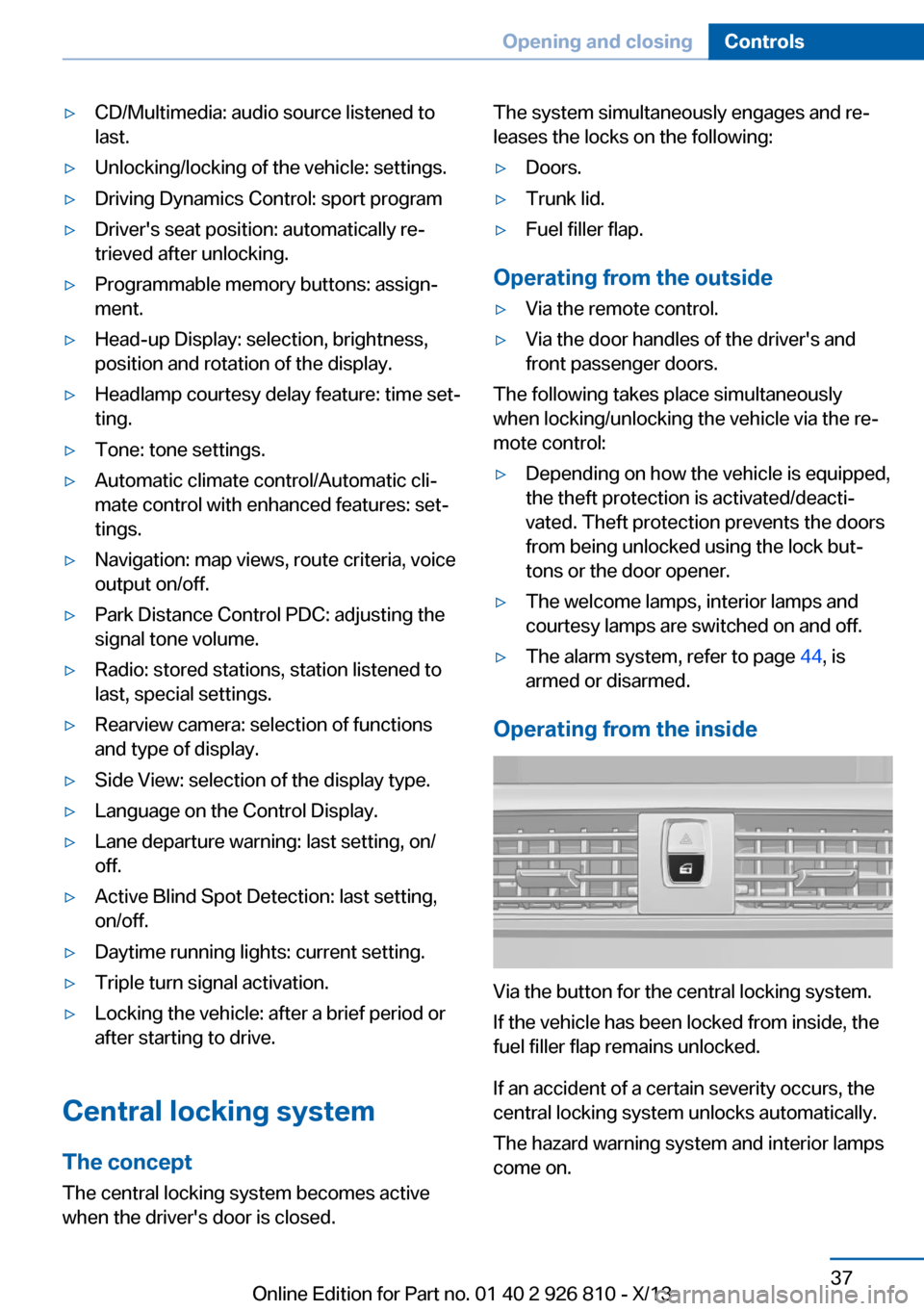
Via the button for the central locking system.
If the vehicle has been locked from inside, the
fuel filler flap remains unlocked.
If an accident of a certain severity occurs, the
central locking system unlocks automatically.
The hazard warning system and interior lamps
come on.
Seite 37Opening and closingControls37
Online Edition for Part no. 01 40 2 926 810 - X/13
Page 47 of 248
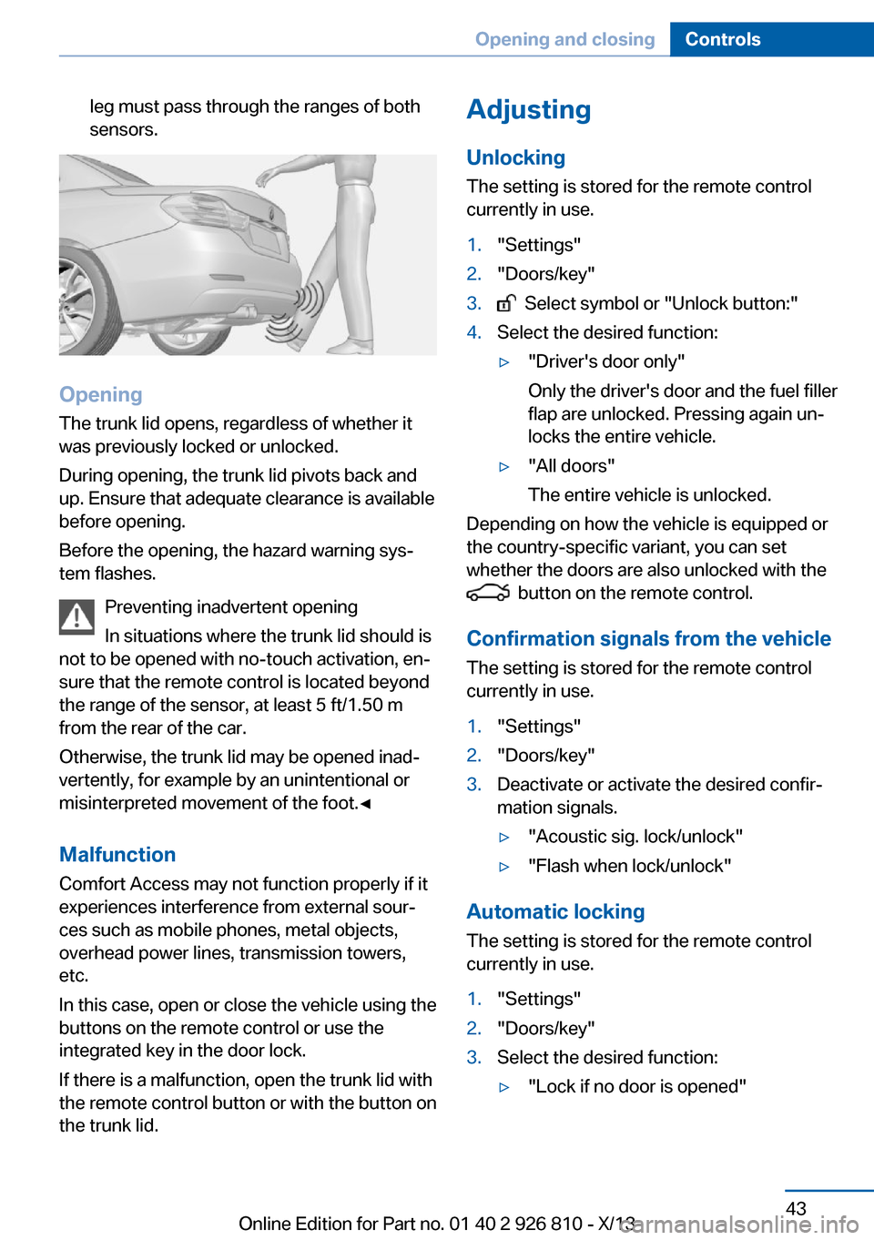
leg must pass through the ranges of both
sensors.
Opening
The trunk lid opens, regardless of whether it
was previously locked or unlocked.
During opening, the trunk lid pivots back and
up. Ensure that adequate clearance is available
before opening.
Before the opening, the hazard warning sys‐
tem flashes.
Preventing inadvertent opening
In situations where the trunk lid should is
not to be opened with no-touch activation, en‐
sure that the remote control is located beyond
the range of the sensor, at least 5 ft/1.50 m
from the rear of the car.
Otherwise, the trunk lid may be opened inad‐
vertently, for example by an unintentional or
misinterpreted movement of the foot.◀
Malfunction
Comfort Access may not function properly if it
experiences interference from external sour‐
ces such as mobile phones, metal objects,
overhead power lines, transmission towers,
etc.
In this case, open or close the vehicle using the
buttons on the remote control or use the
integrated key in the door lock.
If there is a malfunction, open the trunk lid with
the remote control button or with the button on
the trunk lid.
Adjusting
Unlocking The setting is stored for the remote control
currently in use.1."Settings"2."Doors/key"3. Select symbol or "Unlock button:"4.Select the desired function:▷"Driver's door only"
Only the driver's door and the fuel filler
flap are unlocked. Pressing again un‐
locks the entire vehicle.▷"All doors"
The entire vehicle is unlocked.
Depending on how the vehicle is equipped or
the country-specific variant, you can set
whether the doors are also unlocked with the
button on the remote control.
Confirmation signals from the vehicle
The setting is stored for the remote control
currently in use.
1."Settings"2."Doors/key"3.Deactivate or activate the desired confir‐
mation signals.▷"Acoustic sig. lock/unlock"▷"Flash when lock/unlock"
Automatic locking
The setting is stored for the remote control
currently in use.
1."Settings"2."Doors/key"3.Select the desired function:▷"Lock if no door is opened"Seite 43Opening and closingControls43
Online Edition for Part no. 01 40 2 926 810 - X/13
Page 79 of 248
DisplaysVehicle equipmentAll standard, country-specific and optional
equipment that is offered in the model series is
described in this chapter. Therefore, equip‐ment is also described that is not available in a
vehicle, e. g., because of the selected optional
equipment or country variant. This also applies
for safety-related functions and systems.
Instrument cluster
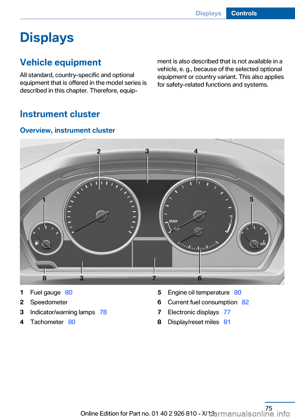
Overview, instrument cluster
1Fuel gauge 802Speedometer3Indicator/warning lamps 784Tachometer 805Engine oil temperature 806Current fuel consumption 827Electronic displays 778Display/reset miles 81Seite 75DisplaysControls75
Online Edition for Part no. 01 40 2 926 810 - X/13
Page 80 of 248
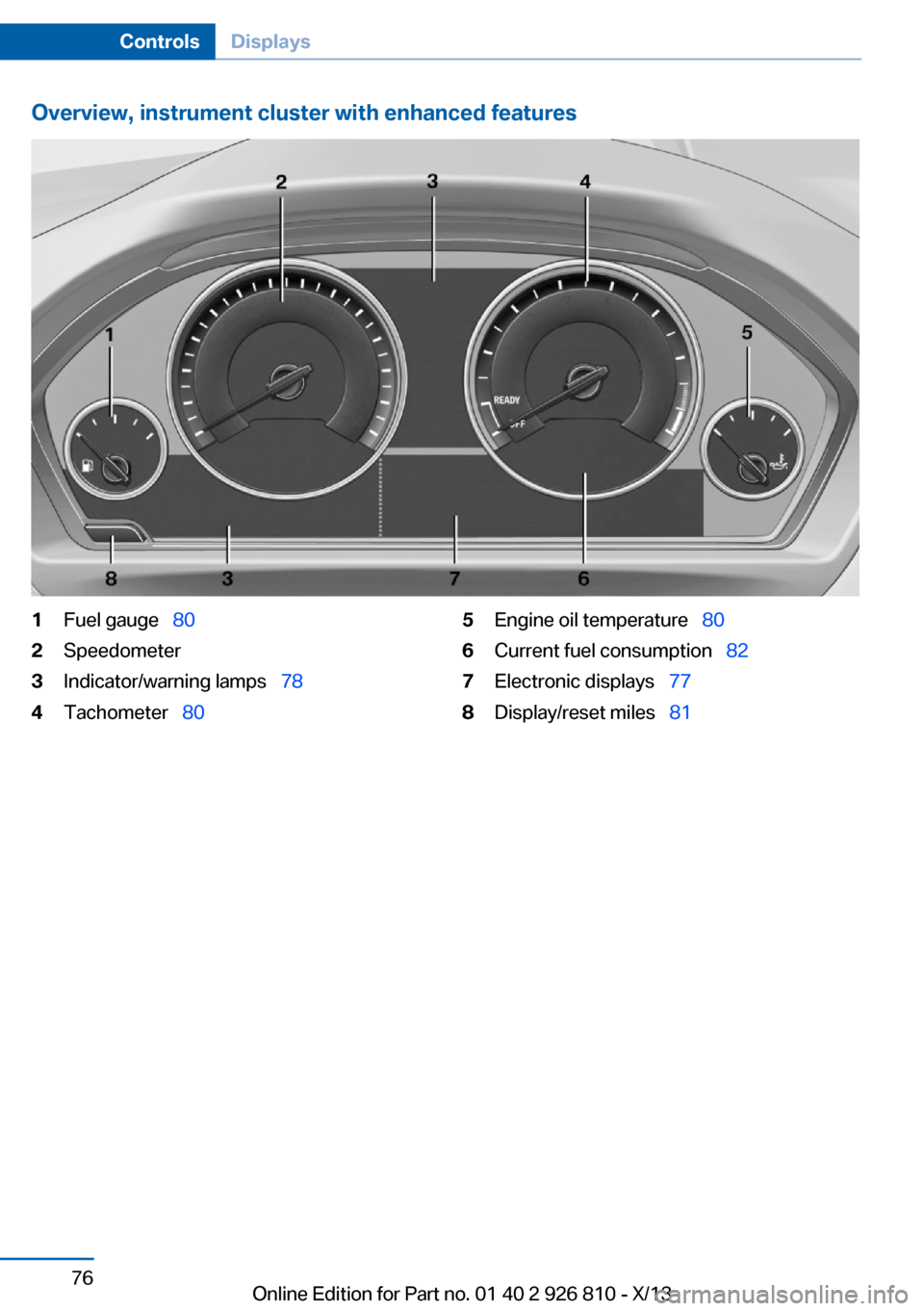
Overview, instrument cluster with enhanced features1Fuel gauge 802Speedometer3Indicator/warning lamps 784Tachometer 805Engine oil temperature 806Current fuel consumption 827Electronic displays 778Display/reset miles 81Seite 76ControlsDisplays76
Online Edition for Part no. 01 40 2 926 810 - X/13
Page 82 of 248
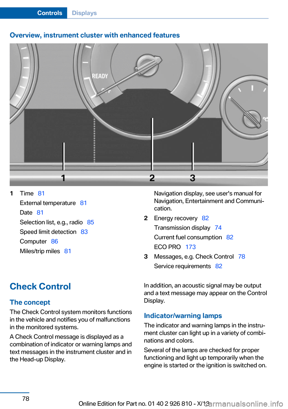
Overview, instrument cluster with enhanced features1Time 81
External temperature 81
Date 81
Selection list, e.g., radio 85
Speed limit detection 83
Computer 86
Miles/trip miles 81Navigation display, see user's manual for
Navigation, Entertainment and Communi‐
cation.2Energy recovery 82
Transmission display 74
Current fuel consumption 82
ECO PRO 1733Messages, e.g. Check Control 78
Service requirements 82Check Control
The concept The Check Control system monitors functions
in the vehicle and notifies you of malfunctions
in the monitored systems.
A Check Control message is displayed as a
combination of indicator or warning lamps and
text messages in the instrument cluster and in
the Head-up Display.In addition, an acoustic signal may be output
and a text message may appear on the Control Display.
Indicator/warning lamps The indicator and warning lamps in the instru‐
ment cluster can light up in a variety of combi‐
nations and colors.
Several of the lamps are checked for proper
functioning and light up temporarily when the
engine is started or the ignition is switched on.Seite 78ControlsDisplays78
Online Edition for Part no. 01 40 2 926 810 - X/13
Page 84 of 248
Symbols
Depending on the Check Control message, the
following functions can be selected.▷ "Owner's Manual"
Display additional information about the
Check Control message in the Integrated
Owner's Manual.▷ "Service request"
Contact your service center.▷ "Roadside Assistance"
Contact Roadside Assistance.
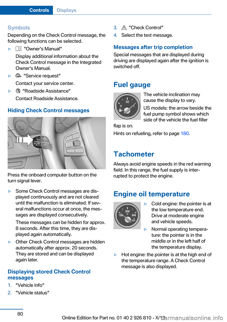
Hiding Check Control messages
Press the onboard computer button on the
turn signal lever.
▷Some Check Control messages are dis‐
played continuously and are not cleared
until the malfunction is eliminated. If sev‐
eral malfunctions occur at once, the mes‐
sages are displayed consecutively.
These messages can be hidden for approx.
8 seconds. After this time, they are dis‐
played again automatically.▷Other Check Control messages are hidden
automatically after approx. 20 seconds.
They are stored and can be displayed
again later.
Displaying stored Check Control
messages
1."Vehicle Info"2."Vehicle status"3. "Check Control"4.Select the text message.
Messages after trip completion
Special messages that are displayed during
driving are displayed again after the ignition is
switched off.
Fuel gauge The vehicle inclination may
cause the display to vary.
US models: the arrow beside the
fuel pump symbol shows which
side of the vehicle the fuel filler
flap is on.
Hints on refueling, refer to page 180.
Tachometer
Always avoid engine speeds in the red warning
field. In this range, the fuel supply is inter‐
rupted to protect the engine.
Engine oil temperature
▷Cold engine: the pointer is at
the low temperature end.
Drive at moderate engine
and vehicle speeds.▷Normal operating tempera‐
ture: the pointer is in the
middle or in the left half of
the temperature display.▷Hot engine: the pointer is at the high end of
the temperature range. A Check Control
message is also displayed.Seite 80ControlsDisplays80
Online Edition for Part no. 01 40 2 926 810 - X/13
Page 85 of 248
Coolant temperatureIf the coolant along with the engine becomes
too hot, a Check Control message is displayed.
Check the coolant level, refer to page 203.
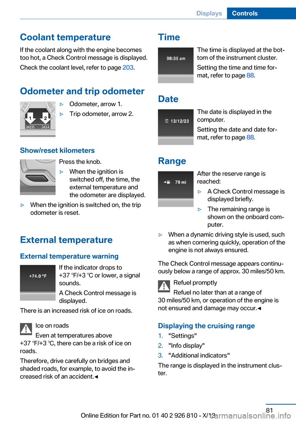
Odometer and trip odometer▷Odometer, arrow 1.▷Trip odometer, arrow 2.
Show/reset kilometers Press the knob.
▷When the ignition is
switched off, the time, the
external temperature and
the odometer are displayed.▷When the ignition is switched on, the trip
odometer is reset.
External temperature
External temperature warning If the indicator drops to
+37 ℉/+3 ℃ or lower, a signal
sounds.
A Check Control message is displayed.
There is an increased risk of ice on roads.
Ice on roads
Even at temperatures above
+37 ℉/+3 ℃, there can be a risk of ice on
roads.
Therefore, drive carefully on bridges and
shaded roads, for example, to avoid the in‐
creased risk of an accident.◀
Time
The time is displayed at the bot‐
tom of the instrument cluster.
Setting the time and time for‐
mat, refer to page 88.
Date The date is displayed in the
computer.
Setting the date and date for‐
mat, refer to page 88.
Range After the reserve range isreached:▷A Check Control message is
displayed briefly.▷The remaining range is
shown on the onboard com‐
puter.▷When a dynamic driving style is used, such
as when cornering quickly, operation of the
engine is not always ensured.
The Check Control message appears continu‐
ously below a range of approx. 30 miles/50 km.
Refuel promptly
Refuel no later than at a range of
30 miles/50 km, or operation of the engine is
not ensured and damage may occur.◀
Displaying the cruising range
1."Settings"2."Info display"3."Additional indicators"
The range is displayed in the instrument clus‐
ter.
Seite 81DisplaysControls81
Online Edition for Part no. 01 40 2 926 810 - X/13
Page 91 of 248
Distance to destination
The distance remaining to the destination is
displayed if a destination is entered in the navi‐
gation system before the trip is started.
The distance to the destination is adopted au‐
tomatically.
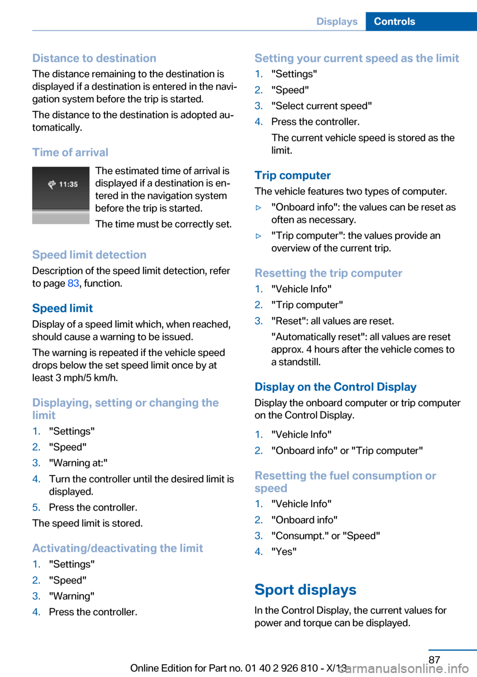
Time of arrival The estimated time of arrival is
displayed if a destination is en‐
tered in the navigation system
before the trip is started.
The time must be correctly set.
Speed limit detection
Description of the speed limit detection, refer
to page 83, function.
Speed limit
Display of a speed limit which, when reached,
should cause a warning to be issued.
The warning is repeated if the vehicle speed
drops below the set speed limit once by at least 3 mph/5 km/h.
Displaying, setting or changing the
limit1."Settings"2."Speed"3."Warning at:"4.Turn the controller until the desired limit is
displayed.5.Press the controller.
The speed limit is stored.
Activating/deactivating the limit
1."Settings"2."Speed"3."Warning"4.Press the controller.Setting your current speed as the limit1."Settings"2."Speed"3."Select current speed"4.Press the controller.
The current vehicle speed is stored as the
limit.
Trip computer
The vehicle features two types of computer.
▷"Onboard info": the values can be reset as
often as necessary.▷"Trip computer": the values provide an
overview of the current trip.
Resetting the trip computer
1."Vehicle Info"2."Trip computer"3."Reset": all values are reset.
"Automatically reset": all values are reset
approx. 4 hours after the vehicle comes to
a standstill.
Display on the Control Display
Display the onboard computer or trip computer
on the Control Display.
1."Vehicle Info"2."Onboard info" or "Trip computer"
Resetting the fuel consumption or
speed
1."Vehicle Info"2."Onboard info"3."Consumpt." or "Speed"4."Yes"
Sport displays
In the Control Display, the current values for
power and torque can be displayed.
Seite 87DisplaysControls87
Online Edition for Part no. 01 40 2 926 810 - X/13
Page 93 of 248
Units of measure
Setting the units of measure
To set the units for fuel consumption, route/
distance and temperature:1."Settings"2."Language/Units"3.Select the desired menu item.4.Select the desired unit.
The setting is stored for the remote control
currently in use.
Brightness
Setting the brightness
To set the brightness of the Control Display:
1."Settings"2."Control display"3."Brightness"4.Turn the controller until the desired bright‐
ness is set.5.Press the controller.
The setting is stored for the remote control
currently in use.
Depending on the light conditions, the bright‐
ness control may not be clearly visible.
Assist system information
Display on the Control Display Information on the Assist system can be dis‐
played by activating Assist on the Control Dis‐
play.
1."Settings"2."Control display"3."Driver assistance info"Head-up Display
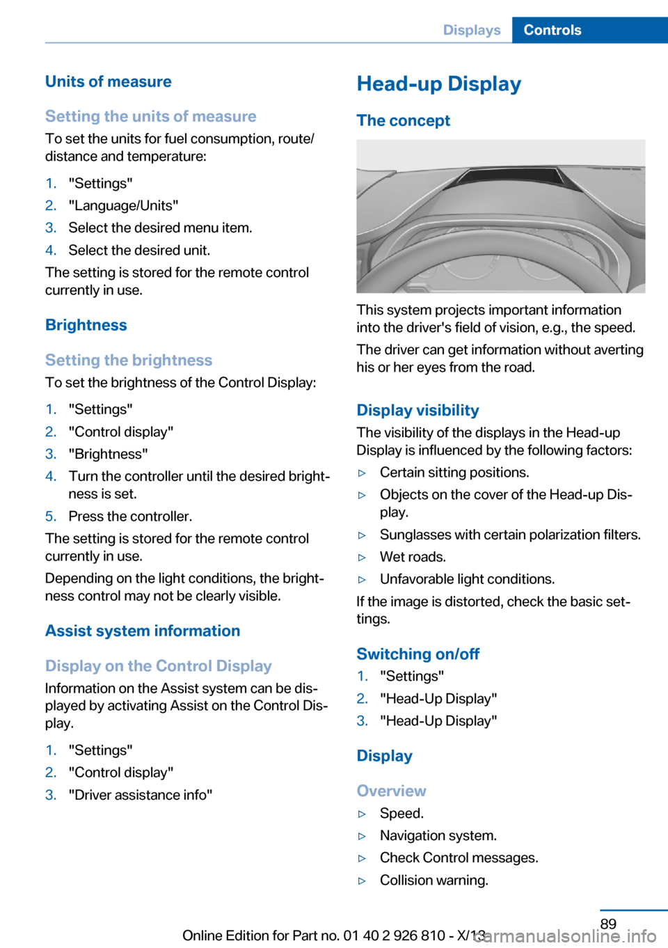
The concept
This system projects important information
into the driver's field of vision, e.g., the speed.
The driver can get information without averting
his or her eyes from the road.
Display visibility The visibility of the displays in the Head-up
Display is influenced by the following factors:
▷Certain sitting positions.▷Objects on the cover of the Head-up Dis‐
play.▷Sunglasses with certain polarization filters.▷Wet roads.▷Unfavorable light conditions.
If the image is distorted, check the basic set‐
tings.
Switching on/off
1."Settings"2."Head-Up Display"3."Head-Up Display"
Display
Overview
▷Speed.▷Navigation system.▷Check Control messages.▷Collision warning.Seite 89DisplaysControls89
Online Edition for Part no. 01 40 2 926 810 - X/13
Page 106 of 248
MalfunctionThe yellow warning lamp flashes andthen lights up continuously. A Check
Control message is displayed. No flat
tire or loss of tire pressure can be detected.
Display in the following situations:▷A wheel without TPM electronics is fitted:
have the service center check it if neces‐
sary.▷Malfunction: have the system checked by
your service center.▷TPM was unable to complete the reset.
Reset the system again.▷Disturbance by systems or devices with
the same radio frequency: after leaving the
area of the disturbance, the system auto‐
matically becomes active again.
Declaration according to NHTSA/
FMVSS 138 Tire Pressure Monitoring
System
Each tire, including the spare (if provided)
should be checked monthly when cold and in‐
flated to the inflation pressure recommended
by the vehicle manufacturer on the vehicle
placard or tire inflation pressure label. (If your
vehicle has tires of a different size than the size
indicated on the vehicle placard or tire inflation
pressure label, you should determine the
proper tire inflation pressure for those tires.)
As an added safety feature, your vehicle has
been equipped with a tire pressure monitoring
system (TPMS) that illuminates a low tire pres‐
sure telltale when one or more of your tires is
significantly under-inflated. Accordingly, when
the low tire pressure telltale illuminates, you
should stop and check your tires as soon as
possible, and inflate them to the proper pres‐
sure. Driving on a significantly under-inflated
tire causes the tire to overheat and can lead to
tire failure. Under-inflation also reduces fuel ef‐
ficiency and tire tread life, and may affect the
vehicle's handling and stopping ability. Please
note that the TPMS is not a substitute for
proper tire maintenance, and it is the driver's
responsibility to maintain correct tire pressure,
even if under-inflation has not reached the
level to trigger illumination of the TPMS low
tire pressure telltale. Your vehicle has also
been equipped with a TPMS malfunction indi‐
cator to indicate when the system is not oper‐
ating properly. The TPMS malfunction indica‐
tor is combined with the low tire pressure
telltale. When the system detects a malfunc‐
tion, the telltale will flash for approximately one
minute and then remain continuously illumi‐
nated. This sequence will continue upon sub‐
sequent vehicle start-ups as long as the mal‐
function exists. When the malfunction indicator
is illuminated, the system may not be able to
detect or signal low tire pressure as intended.
TPMS malfunctions may occur for a variety of
reasons, including the installation of replace‐
ment or alternate tires or wheels on the vehicle
that prevent the TPMS from functioning prop‐
erly. Always check the TPMS malfunction tell‐
tale after replacing one or more tires or wheels
on your vehicle to ensure that the replacement
or alternate tires and wheels allow the TPMS
to continue to function properly.
FTM Flat Tire Monitor The conceptThe system detects a pressure loss on the ba‐sis of speed differences between the individual
wheels while driving.
In the event of a pressure loss, the diameter
and therefore the rotational speed of the corre‐
sponding wheel change. This is detected and
reported as a flat tire.
The system does not measure the actual infla‐
tion pressure in the tires.
Functional requirements
The system must have been initialized when
the tire inflation pressure was correct; other‐
wise, reliable signaling of a flat tire is not en‐Seite 102ControlsSafety102
Online Edition for Part no. 01 40 2 926 810 - X/13