sensor BMW 3 SERIES SEDAN 2014 F30 User Guide
[x] Cancel search | Manufacturer: BMW, Model Year: 2014, Model line: 3 SERIES SEDAN, Model: BMW 3 SERIES SEDAN 2014 F30Pages: 242, PDF Size: 7.25 MB
Page 97 of 242
Detected child seatsThe system generally detects children seated
in a child seat, especially in the child seats that
were required by NHTSA when the vehicle was
manufactured. After installing a child seat,
make sure that the indicator lamp for the front
passenger airbags lights up. This indicates that the child seat has been detected and the
front passenger airbags are not activated.
Strength of the driver's and front
passenger airbag
The strength with which the driver's and front
passenger airbags are triggered depends on
the position of the driver's and front passenger
seats.
To maintain the accuracy of this function over
the long-term, calibrate the front seats when a
corresponding message appears on the Con‐
trol Display.
Calibrating the front seats A corresponding message appears on the
Control Display.1.Move the respective seat forward all the
way.2.Move the respective seat forward again. It
moves forward briefly.3.Readjust the seat to the desired position.
The calibration procedure is completed when
the message on the Control Display disap‐
pears.
If the message continues to be displayed, re‐
peat the calibration.
If the message does not disappear after a re‐
peat calibration, have the system checked as
soon as possible.
Unobstructed area of movement
Ensure that the area of movement of the
seats is unobstructed to avoid personal injury
or damage to objects.◀
Tire Pressure Monitor TPM
The concept The system monitors tire pressure in the four
mounted tires. The system warns you if there
is a significant loss of pressure in one or more
tires. For this purpose, sensors in the tire
valves measure the tire inflation pressure.
Hints Tire damage due to external factors
Sudden tire damage caused by external
influences cannot be indicated in advance.◀
Pay attention to the other information and indi‐
cations under Tire inflation pressure, refer to
page 185, as well when using the system.
Functional requirements
The system must have been reset with the
correct tire inflation pressure; otherwise, relia‐
ble signaling of tire pressure loss is not en‐
sured.
Reset the system after each adjustment of the
tire inflation pressure and after every tire or
wheel change.
Always use wheels with TPM electronics to
ensure that the system will operate properly.
Status display The current status of the Tire Pressure Moni‐
tor TPM can be displayed on the Control Dis‐
play, e.g., whether or not the TPM is active.1."Vehicle Info"2."Vehicle status"3. "Tire Pressure Monitor (TPM)"
The status is displayed.
Status control display The tire and system status is indicated by the
color of the wheels and a text message on the
Control Display.
Seite 97SafetyControls97
Online Edition for Part no. 01 40 2 925 743 - II/14
Page 106 of 242
Prewarning sensitivityDepending on the set prewarning time, this
may result in increased false warnings.
Collision warning withbraking function
The concept
The system issues a warning if there is immi‐
nent danger of a collision and also includes a
braking function.
If the vehicle is equipped with Active Cruise
Control with Stop & Go, the collision warning is
controlled via the cruise control radar sensor.
The collision warning is available even if cruise
control has been deactivated.
When the vehicle is intentionally brought close
to a vehicle, the collision warning is delayed to
avoid false warnings.
General information The system issues a two-phase warning of a
possible danger of collision with vehicles at
speeds above approx. 3 mph/5 km/h. The time
of these warnings may vary depending on the
current driving situation.
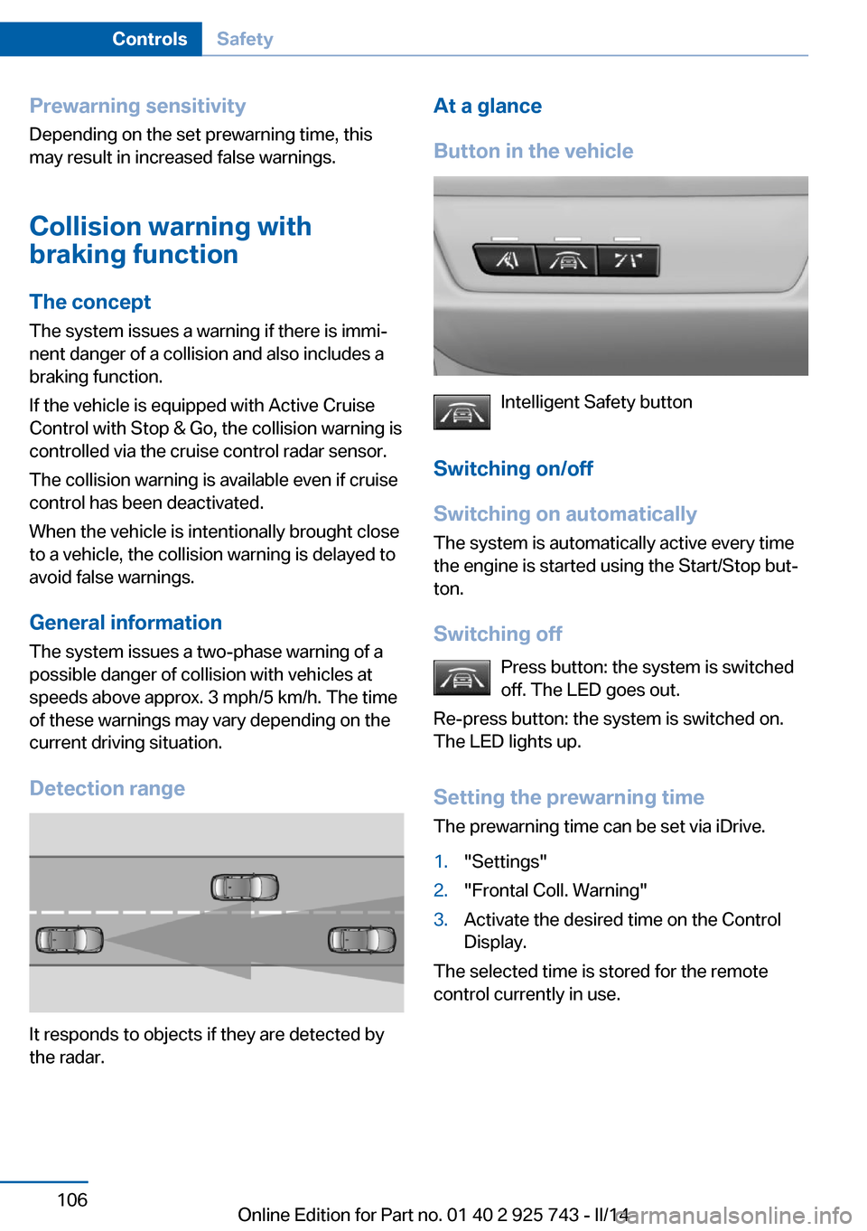
Detection range
It responds to objects if they are detected by
the radar.
At a glance
Button in the vehicle
Intelligent Safety button
Switching on/off
Switching on automatically The system is automatically active every time
the engine is started using the Start/Stop but‐
ton.
Switching off Press button: the system is switchedoff. The LED goes out.
Re-press button: the system is switched on.
The LED lights up.
Setting the prewarning time The prewarning time can be set via iDrive.
1."Settings"2."Frontal Coll. Warning"3.Activate the desired time on the Control
Display.
The selected time is stored for the remote
control currently in use.
Seite 106ControlsSafety106
Online Edition for Part no. 01 40 2 925 743 - II/14
Page 108 of 242
This may result in the warning not being is‐
sued or being issued late.
For example, the following situations may not
be detected:▷Slow moving vehicles when you approach
them at high speed.▷Vehicles that suddenly swerve in front of
you or sharply decelerating vehicles.▷Vehicles with an unusual rear appearance.▷Two-wheeled vehicles ahead of you.▷Pedestrians.▷Stationary objects.
Functional limitations
The system may not be fully functional in the
following situations:
▷In heavy fog, rain, sprayed water or snow‐
fall.▷In tight curves.▷If the driving stability control systems are
limited or deactivated, for example, DSC
OFF.▷If the radar sensor is dirty or obscured.
Prewarning sensitivity
Depending on the set prewarning time, this
may result in increased false warnings.
Pedestrian warning with citybraking function
The concept
The system can help to prevent accidents with
pedestrians.
The system issues a warning in the city driving
speed area if there is imminent danger of a col‐
lision with pedestrians and includes a braking
function.
The system is controlled via the camera in the
base of the interior mirror.
General information
The system issues a warning with brightness
staring at approx. 6 mph/10 km/h to approx.
35 mph/60 km/h regarding a possible risk of
collision with pedestrians and assists with a
brake intervention shortly before a collision.
It responds to persons that are within the de‐
tection range of the system.
Detection range
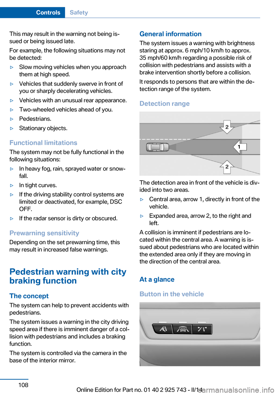
The detection area in front of the vehicle is div‐
ided into two areas.
▷Central area, arrow 1, directly in front of the
vehicle.▷Expanded area, arrow 2, to the right and
left.
A collision is imminent if pedestrians are lo‐
cated within the central area. A warning is is‐
sued about pedestrians who are located within
the extended area only if they are moving in
the direction of the central area.
At a glance
Button in the vehicle
Seite 108ControlsSafety108
Online Edition for Part no. 01 40 2 925 743 - II/14
Page 111 of 242
Camera
The camera is located near the base of the
mirror.
Keep the windshield in the area behind the in‐
terior rear view mirror clean and clear.
Switching on/off Press the button.
▷On: the LED lights up.▷Off: the LED goes out.
The setting is stored for the remote control
currently in use.
Display in the instrument cluster
▷Lines: system is activated.▷Arrows: at least one lane marking
was detected and warnings can be
issued.
Issued warning
If you leave the lane and if a lane marking has
been detected, the steering wheel begins vi‐
brating.
If the turn signal is set before changing the
lane, a warning is not issued.
End of warning
The warning ends:
▷Automatically after approx. 3 seconds.▷When returning to your own lane.▷When braking hard.▷When using the turn signal.
System limits
The system may not be fully functional in the
following situations:
▷In heavy fog, rain or snowfall.▷In the event of missing, worn, poorly visi‐
ble, merging, diverging, or multiple lane
markings such as in construction areas.▷When lane markings are covered in snow,
ice, dirt or water.▷In tight curves or on narrow lanes.▷When the lane markings are covered by
objects.▷When driving very close to the vehicle in
front of you.▷When driving toward bright lights.▷When the windshield in front of the interior
rearview mirror is fogged over, dirty or cov‐
ered with stickers, etc.▷During calibration of the camera immedi‐
ately after vehicle shipment.
Active Blind Spot Detection
The concept
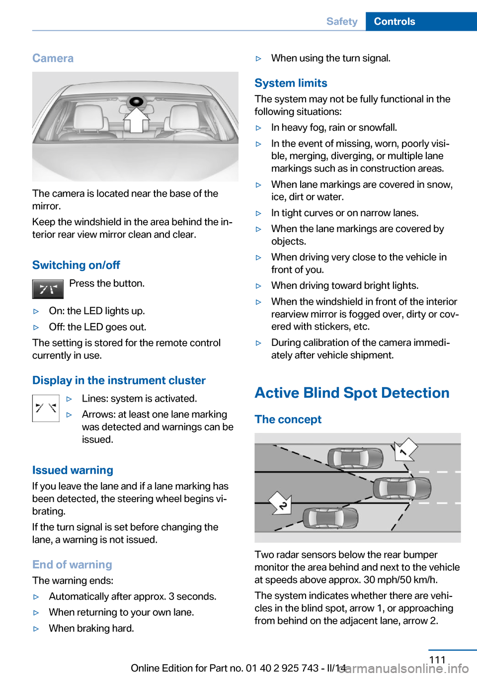
Two radar sensors below the rear bumper
monitor the area behind and next to the vehicle
at speeds above approx. 30 mph/50 km/h.
The system indicates whether there are vehi‐
cles in the blind spot, arrow 1, or approaching
from behind on the adjacent lane, arrow 2.
Seite 111SafetyControls111
Online Edition for Part no. 01 40 2 925 743 - II/14
Page 112 of 242
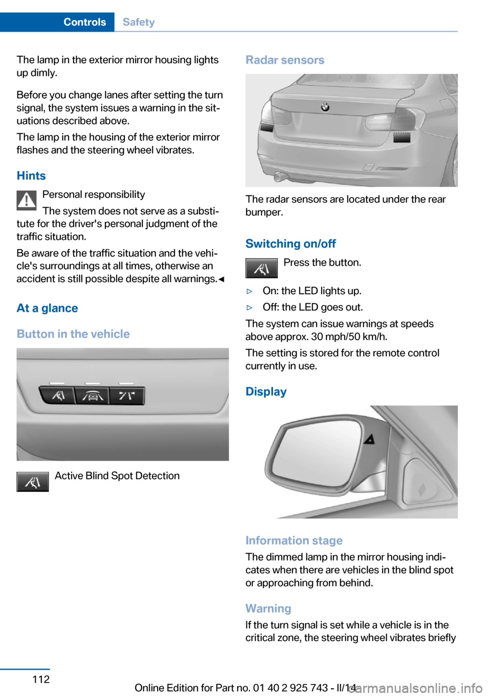
The lamp in the exterior mirror housing lights
up dimly.
Before you change lanes after setting the turn
signal, the system issues a warning in the sit‐
uations described above.
The lamp in the housing of the exterior mirror
flashes and the steering wheel vibrates.
Hints Personal responsibility
The system does not serve as a substi‐
tute for the driver's personal judgment of the
traffic situation.
Be aware of the traffic situation and the vehi‐
cle's surroundings at all times, otherwise an
accident is still possible despite all warnings.◀
At a glance
Button in the vehicle
Active Blind Spot Detection
Radar sensors
The radar sensors are located under the rear
bumper.
Switching on/off Press the button.
▷On: the LED lights up.▷Off: the LED goes out.
The system can issue warnings at speeds
above approx. 30 mph/50 km/h.
The setting is stored for the remote control
currently in use.
Display
Information stage
The dimmed lamp in the mirror housing indi‐
cates when there are vehicles in the blind spot
or approaching from behind.
Warning
If the turn signal is set while a vehicle is in the
critical zone, the steering wheel vibrates briefly
Seite 112ControlsSafety112
Online Edition for Part no. 01 40 2 925 743 - II/14
Page 120 of 242
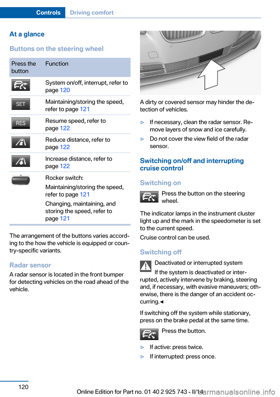
At a glance
Buttons on the steering wheelPress the
buttonFunctionSystem on/off, interrupt, refer to
page 120Maintaining/storing the speed,
refer to page 121Resume speed, refer to
page 122Reduce distance, refer to
page 122Increase distance, refer to
page 122Rocker switch:
Maintaining/storing the speed,
refer to page 121
Changing, maintaining, and
storing the speed, refer to
page 121
The arrangement of the buttons varies accord‐
ing to the how the vehicle is equipped or coun‐
try-specific variants.
Radar sensor
A radar sensor is located in the front bumper
for detecting vehicles on the road ahead of the
vehicle.
A dirty or covered sensor may hinder the de‐
tection of vehicles.
▷If necessary, clean the radar sensor. Re‐
move layers of snow and ice carefully.▷Do not cover the view field of the radar
sensor.
Switching on/off and interrupting cruise control
Switching on Press the button on the steering
wheel.
The indicator lamps in the instrument cluster
light up and the mark in the speedometer is set
to the current speed.
Cruise control can be used.
Switching off Deactivated or interrupted system
If the system is deactivated or inter‐
rupted, actively intervene by braking, steering
and, if necessary, with evasive maneuvers; oth‐
erwise, there is the danger of an accident oc‐
curring.◀
If switching off the system while stationary,
press on the brake pedal at the same time.
Press the button.
▷If active: press twice.▷If interrupted: press once.Seite 120ControlsDriving comfort120
Online Edition for Part no. 01 40 2 925 743 - II/14
Page 122 of 242
If active, the displayed speed is stored and the
vehicle reaches the stored speed if the road is
clear.▷Each time the rocker switch is pressed to
the point of resistance, the desired speed
increases or decreases by approx.
1 mph/1 km/h.▷Each time the rocker switch is pressed
past the point of resistance, the desired
speed increases or decreases by a maxi‐
mum of 5 mph/10 km/h.
Hold the rocker switch in position to repeat the
action.
Distance Selecting a distance
Adjust the distance according to the traf‐
fic and weather conditions; otherwise, there is
the danger of an accident occurring. Maintain
the prescribed safety distance.◀
Reduce distance Press the button repeatedly until the
desired distance is set.
The selected distance, refer to page 123, is
displayed in the instrument cluster.
Increase distance Press the button repeatedly until the
desired distance is set.
The selected distance, refer to page 123, is
displayed in the instrument cluster.
Calling up the desired speed and distance
While driving Press the button with the system
switched on.
In the following cases, the stored speed value
is deleted and cannot be called up again:
▷When the system is switched off.▷When the ignition is switched off.
While standing
Before leaving the vehicle, secure it
against rolling
Before leaving the vehicle with the engine run‐
ning, engage position P of the automatic trans‐
mission and apply the parking brake. Other‐
wise, the vehicle may begin to roll.◀
The system brought the vehicle to a complete
standstill.
▷Green marking in the speedometer:
Your vehicle accelerates automatically as
soon as the vehicle in the range of the ra‐
dar sensor moves off.▷Marking in the speedometer turns orange:
no automatic driving away.
To accelerate to the desired speed auto‐
matically, press the accelerator or press
the RES or SET button.
Rolling bars in the distance display indicate
that the vehicle in the radar sensor detection
range has moved off.
Your vehicle was braked to a halt by pressing
on the brake pedal and it is standing behind
another vehicle:
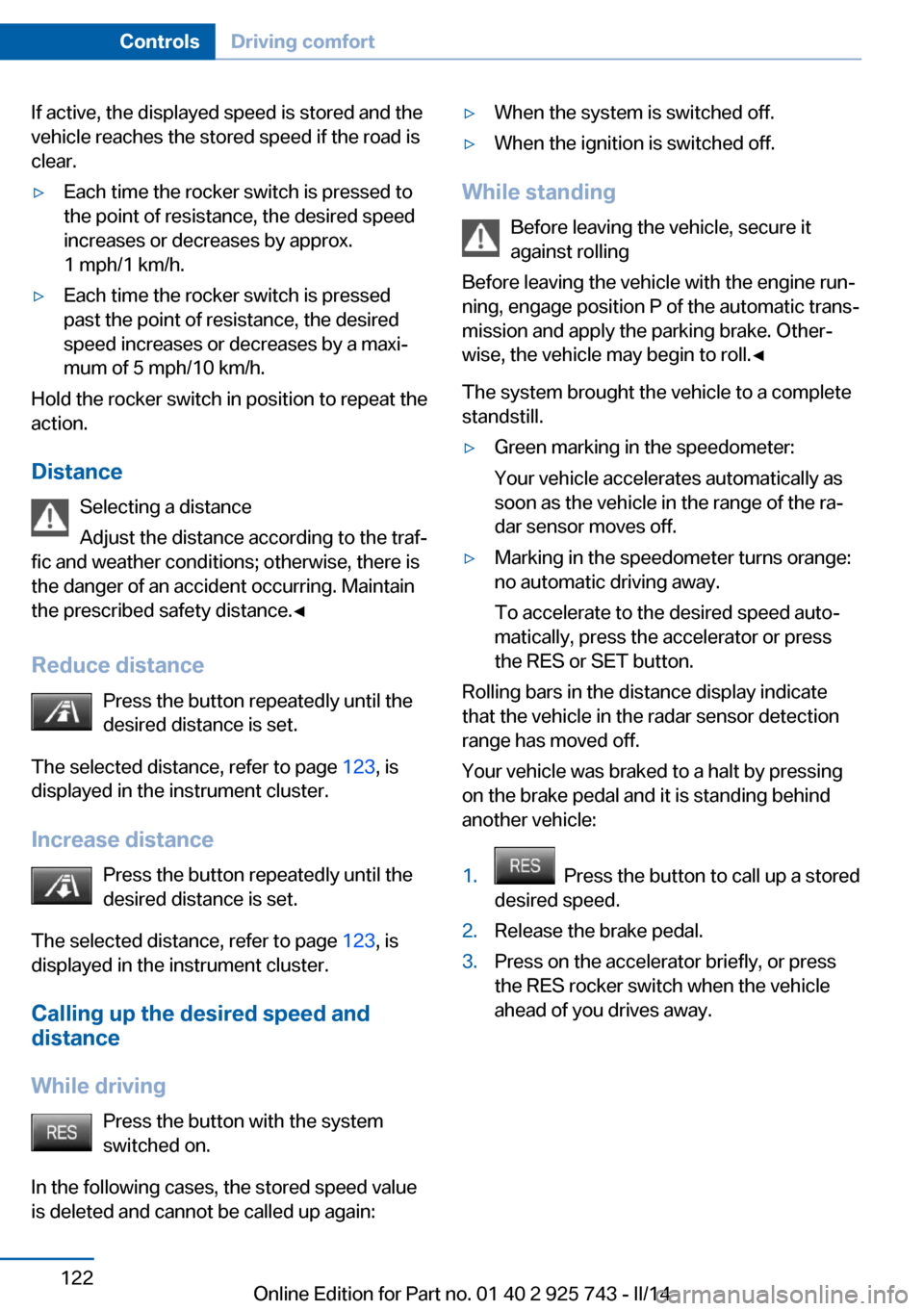
1. Press the button to call up a stored
desired speed.2.Release the brake pedal.3.Press on the accelerator briefly, or press
the RES rocker switch when the vehicle
ahead of you drives away.Seite 122ControlsDriving comfort122
Online Edition for Part no. 01 40 2 925 743 - II/14
Page 125 of 242
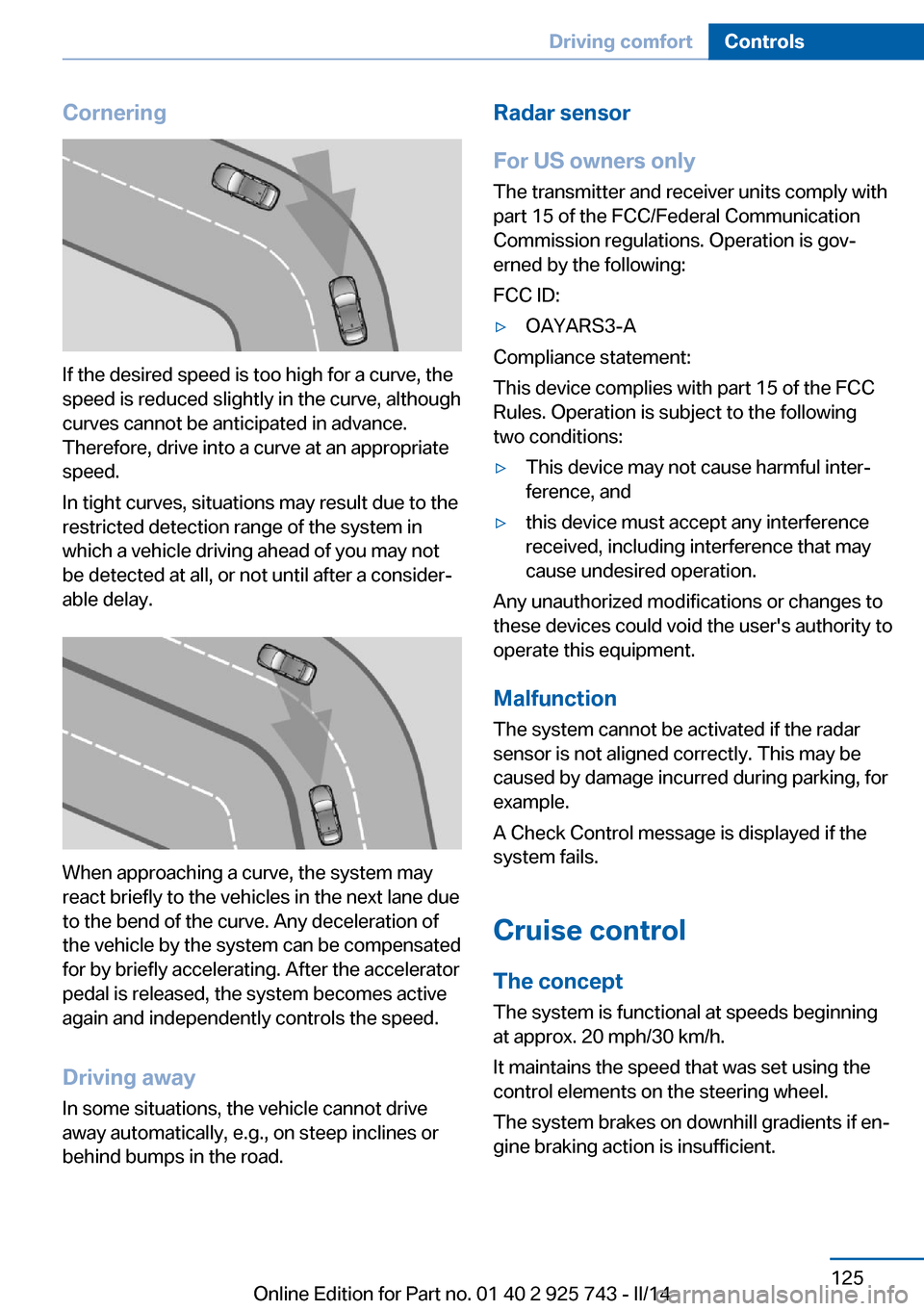
Cornering
If the desired speed is too high for a curve, the
speed is reduced slightly in the curve, although
curves cannot be anticipated in advance.
Therefore, drive into a curve at an appropriate
speed.
In tight curves, situations may result due to the
restricted detection range of the system in
which a vehicle driving ahead of you may not
be detected at all, or not until after a consider‐
able delay.
When approaching a curve, the system may
react briefly to the vehicles in the next lane due
to the bend of the curve. Any deceleration of
the vehicle by the system can be compensated
for by briefly accelerating. After the accelerator
pedal is released, the system becomes active
again and independently controls the speed.
Driving away In some situations, the vehicle cannot drive
away automatically, e.g., on steep inclines or
behind bumps in the road.
Radar sensor
For US owners only
The transmitter and receiver units comply with
part 15 of the FCC/Federal Communication
Commission regulations. Operation is gov‐
erned by the following:
FCC ID:▷OAYARS3-A
Compliance statement:
This device complies with part 15 of the FCC
Rules. Operation is subject to the following
two conditions:
▷This device may not cause harmful inter‐
ference, and▷this device must accept any interference
received, including interference that may
cause undesired operation.
Any unauthorized modifications or changes to
these devices could void the user's authority to
operate this equipment.
Malfunction
The system cannot be activated if the radar sensor is not aligned correctly. This may be
caused by damage incurred during parking, for
example.
A Check Control message is displayed if the
system fails.
Cruise control The concept The system is functional at speeds beginning
at approx. 20 mph/30 km/h.
It maintains the speed that was set using the
control elements on the steering wheel.
The system brakes on downhill gradients if en‐
gine braking action is insufficient.
Seite 125Driving comfortControls125
Online Edition for Part no. 01 40 2 925 743 - II/14
Page 128 of 242
▷The marking does not light up: the system
is switched off.
Brief status display
Selected desired speed.
If --- appears briefly on the display for Check
Control messages, it is possible that the sys‐
tem requirements for operation are currently
not met.
PDC Park Distance Control
The concept PDC support when parking. Slowly approach‐
ing an object behind or, with the appropriate
PDC equipment, also in front of your vehicle is
signaled by:
▷Signal tones.▷Visual display.
General information
Measurements are made by ultrasound sen‐
sors in the bumpers.
The range, depending on the obstacle and en‐
vironmental conditions, is approx. 6 ft/2 m.
An acoustic warning is first given:
▷By the front sensors and the two rear cor‐
ner sensors at approx. 24 in/60 cm.▷By the rear middle sensors at approx.
5 ft/1.50 m.
To ensure full operability:
▷Do not cover sensors, e.g., by stickers, bi‐
cycle racks and the like.▷Keep the sensors clean and free of ice.▷When using high-pressure washers, do not
spray the sensors for long periods and
maintain a distance of at least 12 in/30 cm.Hints
Personal responsibility
Even an active system does not relieve
the driver from personal responsibility for the
driving process.
Because of technical system limits, the system
cannot independently react appropriately in all
traffic situations.
Continuously and attentively monitor the driv‐
ing process, the area surrounding the vehicle
and the traffic situation, and actively intervene
when required, otherwise, there is a risk of an
accident.◀
Avoid driving quickly with PDC
Avoid approaching an object quickly.
Avoid driving away quickly while PDC is not yet
active.
For technical reasons, the system may other‐
wise be too late in issuing a warning.◀
At a glance
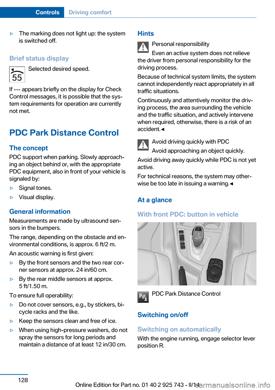
With front PDC: button in vehicle
PDC Park Distance Control
Switching on/off
Switching on automatically With the engine running, engage selector lever
position R.
Seite 128ControlsDriving comfort128
Online Edition for Part no. 01 40 2 925 743 - II/14
Page 129 of 242
Automatic deactivation during forward
travel
The system switches off when a certain driving
distance or speed is exceeded.
Switch the system back on if necessary.
With front PDC: switching on/off
manually
Press the button.▷On: the LED lights up.▷Off: the LED goes out.
Display
Signal tones When approaching an object, an intermittent
tone is sounded that indicates the position of
the object. For example, if an object is de‐
tected to the left rear of the vehicle, a signal
tone sounds from the left rear speaker.
The shorter the distance to the object be‐
comes, the shorter the intervals.
If the distance to a detected object is less than
approx. 10 in/25 cm, a continuous tone is
sounded.
With front PDC: if objects are located both in
front of and behind the vehicle, an alternating
continuous signal is sounded.
The signal tone is switched off:
▷When the vehicle moves away from an ob‐
ject by more than approx. 4 in/10 cm.▷When selector lever position P is engaged
on vehicles with automatic transmission.
Volume
The volume of the PDC signal tone can be ad‐
justed similar to the tone and volume settings
of the radio.
The setting is stored for the remote control
currently in use.
Visual warning
The approach of the vehicle to an object can
be shown on the Control Display. Objects that
are farther away are displayed on the Control
Display before a signal tone sounds.
A display appears as soon as Park Distance
Control (PDC) is activated.
The range of the sensors is represented in the
colors red, green and yellow.
When the image of the rearview camera is dis‐
played, the switch can be made to PDC:
"Rear view camera"
System limits
Limits of ultrasonic measurement The detection of objects can reach the physi‐
cal limits of ultrasonic measurement, e.g., in
the following circumstances:
▷For small children and animals.▷For persons with certain clothing, e.g.
coats.▷If there is an external disturbance of the ul‐
trasound, e.g. from passing vehicles or
loud machines.▷When sensors are dirty, iced over, dam‐
aged or out of position.▷Under certain weather conditions, such as
high relative humidity, rain, snowfall ex‐
treme heat or strong wind.▷With tow bars and trailer hitches of other
vehicles.▷With thin or wedge-shaped objects.▷With moving objects.▷With elevated, protruding objects such as
ledges or cargo.▷With objects with corners and sharp edges.▷With objects with a fine surface structure,
such as fences.▷For objects with porous surfaces.Seite 129Driving comfortControls129
Online Edition for Part no. 01 40 2 925 743 - II/14