vent BMW 3 SERIES SPORTS WAGON 2014 F31 Repair Manual
[x] Cancel search | Manufacturer: BMW, Model Year: 2014, Model line: 3 SERIES SPORTS WAGON, Model: BMW 3 SERIES SPORTS WAGON 2014 F31Pages: 253, PDF Size: 6.35 MB
Page 218 of 253
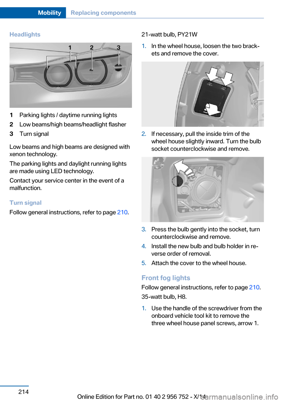
Headlights1Parking lights / daytime running lights2Low beams/high beams/headlight flasher3Turn signal
Low beams and high beams are designed with
xenon technology.
The parking lights and daylight running lights
are made using LED technology.
Contact your service center in the event of a
malfunction.
Turn signal
Follow general instructions, refer to page 210.
21-watt bulb, PY21W1.In the wheel house, loosen the two brack‐
ets and remove the cover.2.If necessary, pull the inside trim of the
wheel house slightly inward. Turn the bulb
socket counterclockwise and remove.3.Press the bulb gently into the socket, turn
counterclockwise and remove.4.Install the new bulb and bulb holder in re‐
verse order of removal.5.Attach the cover to the wheel house.
Front fog lights
Follow general instructions, refer to page 210.
35-watt bulb, H8.
1.Use the handle of the screwdriver from the
onboard vehicle tool kit to remove the
three wheel house panel screws, arrow 1.Seite 214MobilityReplacing components214
Online Edition for Part no. 01 40 2 956 752 - X/14
Page 219 of 253
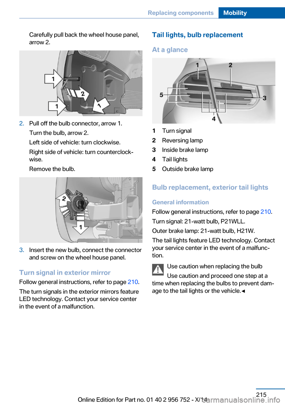
Carefully pull back the wheel house panel,
arrow 2.2.Pull off the bulb connector, arrow 1.
Turn the bulb, arrow 2.
Left side of vehicle: turn clockwise.
Right side of vehicle: turn counterclock‐
wise.
Remove the bulb.3.Insert the new bulb, connect the connector
and screw on the wheel house panel.
Turn signal in exterior mirror
Follow general instructions, refer to page 210.
The turn signals in the exterior mirrors feature
LED technology. Contact your service center
in the event of a malfunction.
Tail lights, bulb replacement
At a glance1Turn signal2Reversing lamp3Inside brake lamp4Tail lights5Outside brake lamp
Bulb replacement, exterior tail lights General information
Follow general instructions, refer to page 210.
Turn signal: 21-watt bulb, P21WLL.
Outer brake lamp: 21-watt bulb, H21W.
The tail lights feature LED technology. Contact
your service center in the event of a malfunc‐
tion.
Use caution when replacing the bulb
Use caution and proceed one step at a
time when replacing the bulbs to prevent dam‐
age to the tail lights or the vehicle.◀
Seite 215Replacing componentsMobility215
Online Edition for Part no. 01 40 2 956 752 - X/14
Page 220 of 253
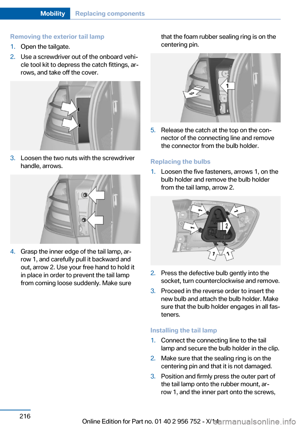
Removing the exterior tail lamp1.Open the tailgate.2.Use a screwdriver out of the onboard vehi‐
cle tool kit to depress the catch fittings, ar‐
rows, and take off the cover.3.Loosen the two nuts with the screwdriver
handle, arrows.4.Grasp the inner edge of the tail lamp, ar‐
row 1, and carefully pull it backward and
out, arrow 2. Use your free hand to hold it
in place in order to prevent the tail lamp
from coming loose suddenly. Make surethat the foam rubber sealing ring is on the
centering pin.5.Release the catch at the top on the con‐
nector of the connecting line and remove
the connector from the bulb holder.
Replacing the bulbs
1.Loosen the five fasteners, arrows 1, on the
bulb holder and remove the bulb holder
from the tail lamp, arrow 2.2.Press the defective bulb gently into the
socket, turn counterclockwise and remove.3.Proceed in the reverse order to insert the
new bulb and attach the bulb holder. Make
sure that the bulb holder engages in all fas‐
teners.
Installing the tail lamp
1.Connect the connecting line to the tail
lamp and secure the bulb holder in the clip.2.Make sure that the sealing ring is on the
centering pin and that it is not damaged.3.Position and firmly press the outer part of
the tail lamp onto the rubber mount, ar‐
row 1, and the inner part onto the screws,Seite 216MobilityReplacing components216
Online Edition for Part no. 01 40 2 956 752 - X/14
Page 221 of 253
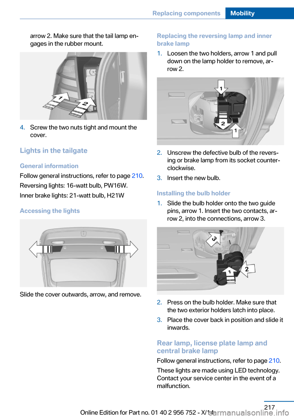
arrow 2. Make sure that the tail lamp en‐
gages in the rubber mount.4.Screw the two nuts tight and mount the
cover.
Lights in the tailgate
General information
Follow general instructions, refer to page 210.
Reversing lights: 16-watt bulb, PW16W.
Inner brake lights: 21-watt bulb, H21W
Accessing the lights
Slide the cover outwards, arrow, and remove.
Replacing the reversing lamp and inner
brake lamp1.Loosen the two holders, arrow 1 and pull
down on the lamp holder to remove, ar‐
row 2.2.Unscrew the defective bulb of the revers‐
ing or brake lamp from its socket counter‐
clockwise.3.Insert the new bulb.
Installing the bulb holder
1.Slide the bulb holder onto the two guide
pins, arrow 1. Insert the two contacts, ar‐
row 2, into the connections, arrow 3.2.Press on the bulb holder. Make sure that
the two exterior holders latch into place.3.Place the cover back in position and slide it
inwards.
Rear lamp, license plate lamp and
central brake lamp
Follow general instructions, refer to page 210.
These lights are made using LED technology.
Contact your service center in the event of a
malfunction.
Seite 217Replacing componentsMobility217
Online Edition for Part no. 01 40 2 956 752 - X/14
Page 222 of 253
Changing wheels
Hints
When using run-flat tires or sealants, a tire
does not need to be changed immediately in
the event of pressure loss due to a flat tire.
Which is why no spare tire is available.
The tools for changing wheels are available as
accessories from your service center.
Jacking points for the vehicle jack
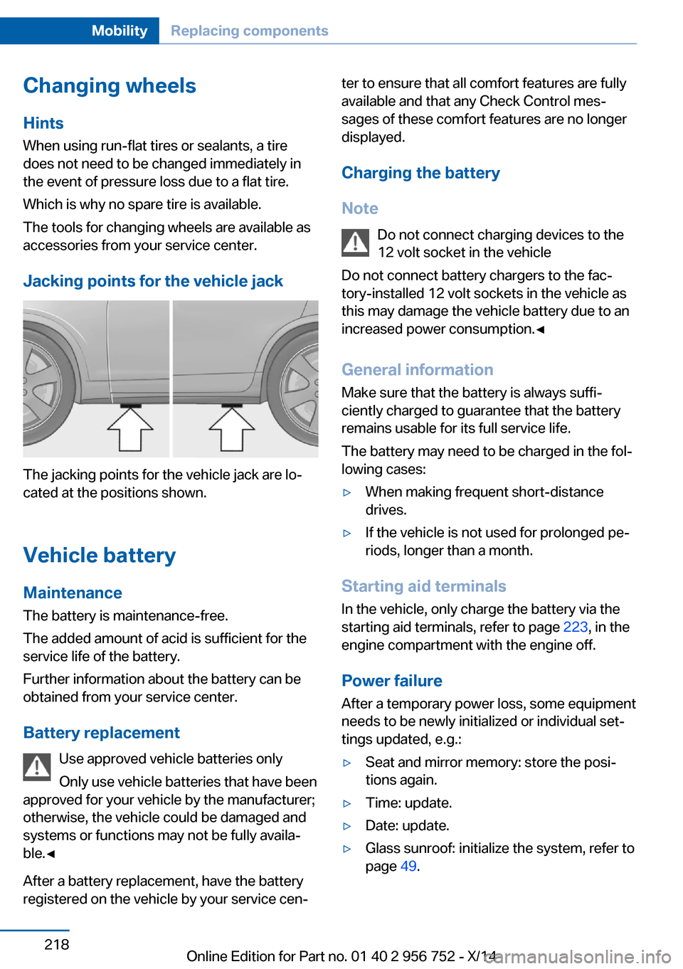
The jacking points for the vehicle jack are lo‐
cated at the positions shown.
Vehicle battery Maintenance
The battery is maintenance-free.
The added amount of acid is sufficient for the
service life of the battery.
Further information about the battery can be
obtained from your service center.
Battery replacement Use approved vehicle batteries only
Only use vehicle batteries that have been
approved for your vehicle by the manufacturer;
otherwise, the vehicle could be damaged and
systems or functions may not be fully availa‐
ble.◀
After a battery replacement, have the battery
registered on the vehicle by your service cen‐
ter to ensure that all comfort features are fully
available and that any Check Control mes‐
sages of these comfort features are no longer
displayed.
Charging the battery
Note Do not connect charging devices to the
12 volt socket in the vehicle
Do not connect battery chargers to the fac‐
tory-installed 12 volt sockets in the vehicle as
this may damage the vehicle battery due to an
increased power consumption.◀
General information Make sure that the battery is always suffi‐
ciently charged to guarantee that the battery
remains usable for its full service life.
The battery may need to be charged in the fol‐
lowing cases:▷When making frequent short-distance
drives.▷If the vehicle is not used for prolonged pe‐
riods, longer than a month.
Starting aid terminals
In the vehicle, only charge the battery via the
starting aid terminals, refer to page 223, in the
engine compartment with the engine off.
Power failure After a temporary power loss, some equipment
needs to be newly initialized or individual set‐
tings updated, e.g.:
▷Seat and mirror memory: store the posi‐
tions again.▷Time: update.▷Date: update.▷Glass sunroof: initialize the system, refer to
page 49.Seite 218MobilityReplacing components218
Online Edition for Part no. 01 40 2 956 752 - X/14
Page 226 of 253
steps to help you under certain circum‐
stances.
For this, data are transmitted to the BMW
Response Center which serve to deter‐
mine the necessary rescue measures. E. g.
the current position of the vehicle, if it can
be established.▷If the LED is flashing green, but the BMW
Response Center can no longer be heard
via the speaker, you can nevertheless still
be heard at the BMW Response Center.
Initiating an Emergency Request
automatically
Under certain conditions, an Emergency Re‐
quest is automatically initiated immediately af‐
ter a severe accident. Automatic Collision Noti‐
fication is not affected by pressing the SOS
button.
Warning triangle
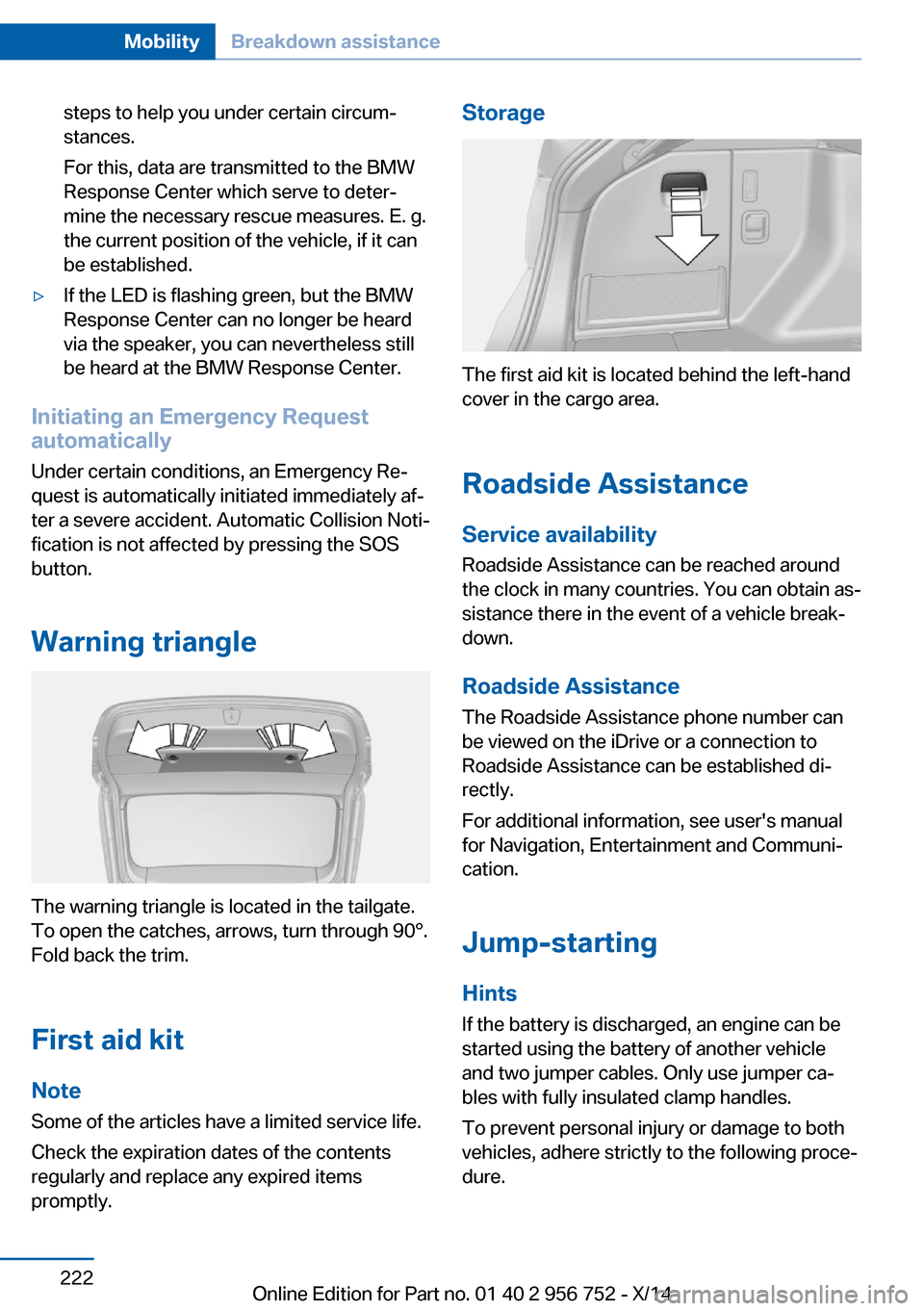
The warning triangle is located in the tailgate.
To open the catches, arrows, turn through 90°.
Fold back the trim.
First aid kit NoteSome of the articles have a limited service life.
Check the expiration dates of the contents
regularly and replace any expired items
promptly.
Storage
The first aid kit is located behind the left-hand
cover in the cargo area.
Roadside Assistance Service availability
Roadside Assistance can be reached around
the clock in many countries. You can obtain as‐
sistance there in the event of a vehicle break‐
down.
Roadside Assistance The Roadside Assistance phone number can
be viewed on the iDrive or a connection to
Roadside Assistance can be established di‐
rectly.
For additional information, see user's manual
for Navigation, Entertainment and Communi‐
cation.
Jump-starting
Hints
If the battery is discharged, an engine can be
started using the battery of another vehicle
and two jumper cables. Only use jumper ca‐
bles with fully insulated clamp handles.
To prevent personal injury or damage to both
vehicles, adhere strictly to the following proce‐
dure.
Seite 222MobilityBreakdown assistance222
Online Edition for Part no. 01 40 2 956 752 - X/14
Page 227 of 253
Do not touch live parts
To avoid the risk of potentially fatal in‐
jury, always avoid all contact with electrical
components while the engine is running.◀
Preparation1.Check whether the battery of the other ve‐
hicle has a voltage of 12 volts. This infor‐
mation can be found on the battery.2.Switch off the engine of the assisting vehi‐
cle.3.Switch off any electronic systems/power
consumers in both vehicles.
Bodywork contact between vehicles
Make sure that there is no contact be‐
tween the bodywork of the two vehicles; other‐
wise, there is a danger of short circuits.◀
Starting aid terminals Connecting order
Connect the jumper cables in the correct
order to prevent risk of injury from arcing.◀
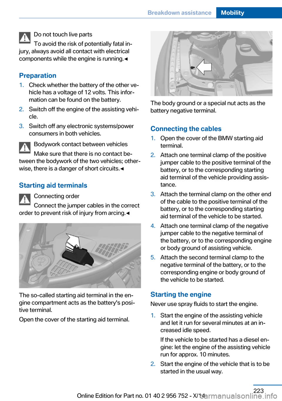
The so-called starting aid terminal in the en‐
gine compartment acts as the battery's posi‐
tive terminal.
Open the cover of the starting aid terminal.
The body ground or a special nut acts as the
battery negative terminal.
Connecting the cables
1.Open the cover of the BMW starting aid
terminal.2.Attach one terminal clamp of the positive
jumper cable to the positive terminal of the
battery, or to the corresponding starting
aid terminal of the vehicle providing assis‐
tance.3.Attach the terminal clamp on the other end
of the cable to the positive terminal of the
battery, or to the corresponding starting
aid terminal of the vehicle to be started.4.Attach one terminal clamp of the negative
jumper cable to the negative terminal of
the battery, or to the corresponding engine
or body ground of assisting vehicle.5.Attach the second terminal clamp to the
negative terminal of the battery, or to the
corresponding engine or body ground of
the vehicle to be started.
Starting the engine
Never use spray fluids to start the engine.
1.Start the engine of the assisting vehicle
and let it run for several minutes at an in‐
creased idle speed.
If the vehicle to be started has a diesel en‐
gine: let the engine of the assisting vehicle
run for approx. 10 minutes.2.Start the engine of the vehicle that is to be
started in the usual way.Seite 223Breakdown assistanceMobility223
Online Edition for Part no. 01 40 2 956 752 - X/14
Page 228 of 253
If the first starting attempt is not success‐
ful, wait a few minutes before making an‐
other attempt in order to allow the dis‐
charged battery to recharge.3.Let both engines run for several minutes.4.Disconnect the jumper cables in the re‐
verse order.
Check the battery and recharge if needed.
Tow-starting and towing Note Tow-starting and towing
For towing the vehicle turn, switch off the
Intelligent Safety systems; otherwise malfunc‐
tions of the individual braking systems might
lead to accidents.◀
Manual transmission Gearshift lever in neutral position.
Towing Follow the towing instructions
Follow all towing instructions; otherwise,
vehicle damage or accidents may occur.◀
▷Make sure that the ignition is switched on;
otherwise, the low beams, tail lights, turn
signals, and wipers may be unavailable.▷Do not tow the vehicle with the rear axle
tilted, as the front wheels could turn.▷When the engine is stopped, there is no
power assist. Consequently, more force
needs to be applied when braking and
steering.▷Larger steering wheel movements are re‐
quired.▷The towing vehicle must not be lighter
than the vehicle being towed; otherwise,
it will not be possible to control the vehi‐
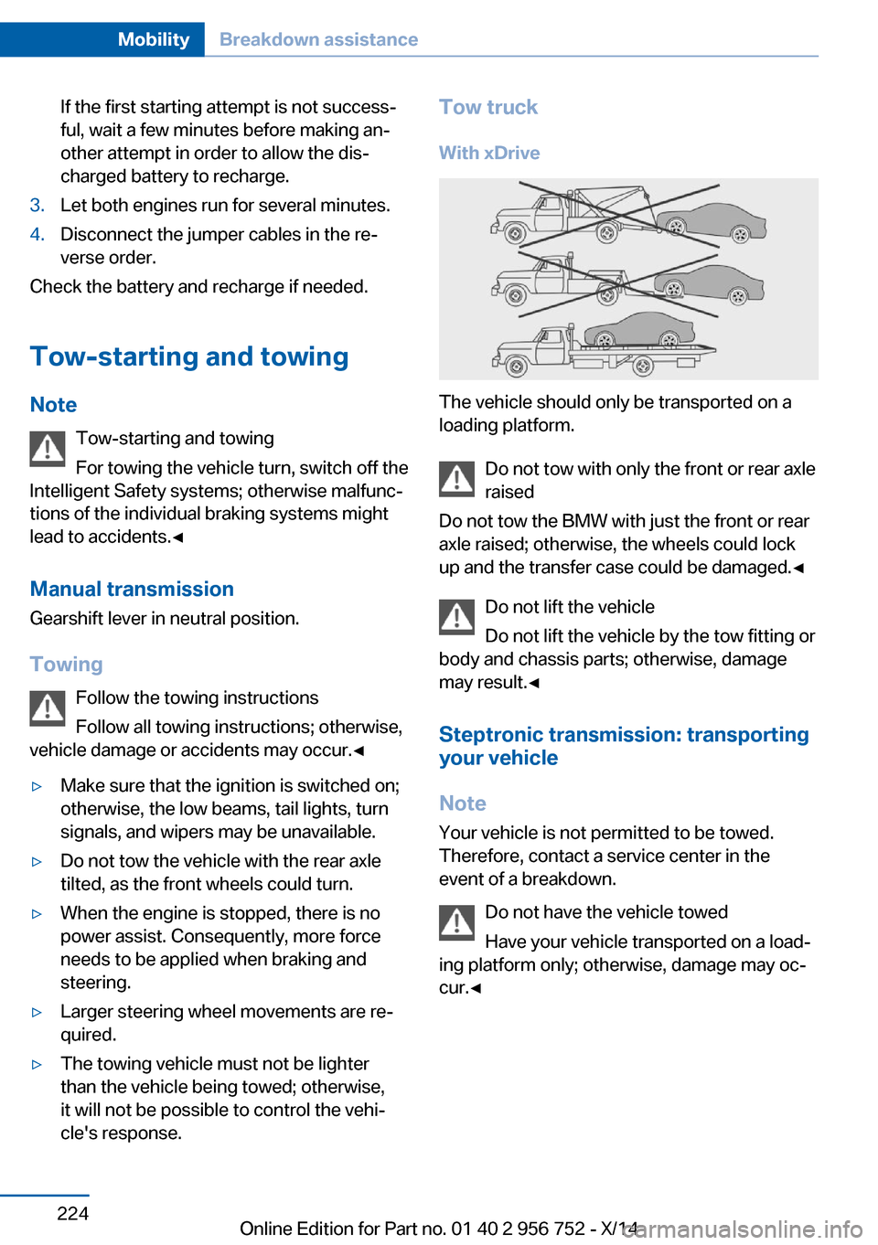
cle's response.Tow truck
With xDrive
The vehicle should only be transported on a
loading platform.
Do not tow with only the front or rear axle
raised
Do not tow the BMW with just the front or rear
axle raised; otherwise, the wheels could lock
up and the transfer case could be damaged.◀
Do not lift the vehicle
Do not lift the vehicle by the tow fitting or
body and chassis parts; otherwise, damage
may result.◀
Steptronic transmission: transporting
your vehicle
Note Your vehicle is not permitted to be towed.
Therefore, contact a service center in the
event of a breakdown.
Do not have the vehicle towedHave your vehicle transported on a load‐
ing platform only; otherwise, damage may oc‐
cur.◀
Seite 224MobilityBreakdown assistance224
Online Edition for Part no. 01 40 2 956 752 - X/14
Page 232 of 253
2.Engage selector lever position N.3.Switch the engine off.
In this way, the ignition remains switched
on, and a Check-Control message is dis‐
played.
Do not turn off the ignition in the car
wash
Do not turn off the ignition in the car wash;
otherwise, selector lever position P is en‐
gaged and damages can result.◀
The vehicle cannot be locked from the outside
when in selector lever position N. A signal
sounds when an attempt is made to lock the
vehicle.
To start the engine with manual transmission:
1.Press on the clutch pedal.2.Press the Start/Stop button.
To start the engine with Steptronic transmis‐
sion:
1.Depress the brake pedal.2.Press the Start/Stop button.
Pressing the Start/Stop button without step‐
ping on the brake turns the ignition off.
Selector lever positionSelector lever position P is engaged automati‐
cally:
▷When the ignition is switched off.▷After approx. 15 minutes.
Headlights
▷Do not rub dry and do not use abrasive or
acidic cleansers.▷Soak areas that have been dirtied e. g.,
from insects, with shampoo and wash off
with water.▷Thaw ice with de-icing spray; do not use an
ice scraper.After washing the vehicle
After washing the vehicle, apply the brakes
briefly to dry them; otherwise, braking action
can be reduced and corrosion of the brake
discs can occur.
Completely remove all residues on the win‐
dows, to minimize loss of visibility due to
smearing and to reduce wiper noises and
wiper blade wear.
Vehicle care
Car care products BMW recommends using care and cleaning
products from BMW, since these have been
tested and approved.
Car care and cleaning products
Follow the instructions on the container.
When cleaning the interior, open the doors or
windows.
Only use products intended for cleaning vehi‐
cles.
Cleansers can contain substances that are
dangerous and harmful to your health.◀
Vehicle paint
Regular care contributes to driving safety and
value retention. Environmental influences in
areas with elevated air pollution or natural con‐
taminants, such as tree resin or pollen can af‐
fect the vehicle's paintwork. Tailor the fre‐
quency and extent of your car care to these
influences.
Aggressive substances such as spilled fuel, oil,
grease or bird droppings, must be removed im‐
mediately to prevent the finish from being al‐
tered or discolored.
Leather care
Remove dust from the leather often, using a
cloth or vacuum cleaner.Seite 228MobilityCare228
Online Edition for Part no. 01 40 2 956 752 - X/14
Page 233 of 253
Otherwise, particles of dust and road grime
chafe in pores and folds, and lead to increased
wear and premature degradation of the leather
surface.
To guard against discoloration, such as from
clothing, provide leather care roughly every
two months.
Clean light-colored leather more frequently be‐
cause soiling on such surfaces is substantially
more visible.
Use leather care products; otherwise, dirt and
grease will gradually break down the protective
layer of the leather surface.
Suitable care products are available from the
service center.
Upholstery material care Vacuum regularly with a vacuum cleaner.
If upholstery is very dirty, e.g., with beverage
stains, use a soft sponge or microfiber cloth
with a suitable interior cleaner.
Clean the upholstery down to the seams using
large sweeping motions. Avoid rubbing the
material vigorously.
Damage from Velcro® fasteners
Open Velcro® fasteners on pants or
other articles of clothing can damage the seat
covers. Ensure that any Velcro® fasteners are
closed.◀
Caring for special components
Light-alloy wheels When cleaning the vehicle, use only neutral
wheel cleaners having a pH value from 5 to 9.
Do not use abrasive cleaning agents or steam
jets above 140 ℉/60 ℃. Follow the manufac‐
turer's instructions.
Aggressive, acidic or alkaline cleaning agents
can destroy the protective layer of adjacent
components, such as the brake disk.Chrome surfaces
Carefully clean components such as the radia‐
tor grille or door handles with an ample supply
of water, possibly with shampoo added, partic‐
ularly when they have been exposed to road
salt.
Rubber components
Aside from water, treat only with rubber
cleansers.
When cleaning rubber seals, do not use any
silicon-containing car care products in order to
avoid damage or noises.
Fine wood partsClean fine wood facing and fine wood compo‐
nents only with a moist rag. Then dry with a
soft cloth.
Plastic components
These include:▷Imitation leather surfaces.▷Roofliner.▷Lamp lenses.▷Instrument cluster cover.▷Matt black spray-coated components.▷Painted parts in the interior.
Clean with a microfiber cloth.
Dampen cloth lightly with water.
Do not soak the roofliner.
No cleansers that contain alcohol or sol‐
vents
Do not use cleansers that contain alcohol or
solvents, such as lacquer thinners, heavy-duty
grease removers, fuel, or such; this could lead
to surface damage.◀
Safety belts
Dirty belt straps impede the reeling action and
thus have a negative impact on safety.
Seite 229CareMobility229
Online Edition for Part no. 01 40 2 956 752 - X/14