tow BMW 3 SERIES SPORTS WAGON 2016 F31 Owner's Guide
[x] Cancel search | Manufacturer: BMW, Model Year: 2016, Model line: 3 SERIES SPORTS WAGON, Model: BMW 3 SERIES SPORTS WAGON 2016 F31Pages: 255, PDF Size: 5.6 MB
Page 169 of 255
Storage compartment in the
rear
A storage compartment is located in the center
armrest.
Cupholders
Hints Shatter-proof containers and no hot
drinks
Use light and shatter-proof containers and do
not transport hot drinks. Otherwise, there is the increased danger of injury in an accident.◀
Unsuitable containers
Do not forcefully push unsuitable con‐
tainers into the cupholders. This may result in
damage.◀
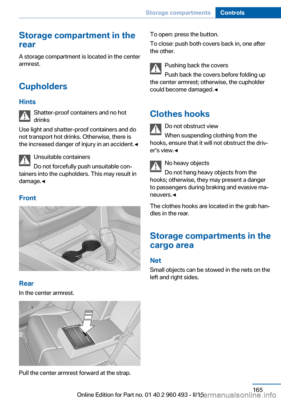
Front
Rear
In the center armrest.
Pull the center armrest forward at the strap.
To open: press the button.
To close: push both covers back in, one after
the other.
Pushing back the covers
Push back the covers before folding up
the center armrest; otherwise, the cupholder
could become damaged.◀
Clothes hooks Do not obstruct view
When suspending clothing from the
hooks, ensure that it will not obstruct the driv‐
er's view.◀
No heavy objects
Do not hang heavy objects from the
hooks; otherwise, they may present a danger
to passengers during braking and evasive ma‐
neuvers.◀
The clothes hooks are located in the grab han‐
dles in the rear.
Storage compartments in the
cargo area
Net
Small objects can be stowed in the nets on the
left and right sides.Seite 165Storage compartmentsControls165
Online Edition for Part no. 01 40 2 960 493 - II/15
Page 171 of 255
3.Hook the retaining strap into the fixing
point.4.Press button 1 to tighten the retaining
strap.
To secure larger loads, the retaining straps can
also be interlocked with one another.
Removing the brackets
Pull the bracket vertically out of the fixing
point.
Stowing the adaptive retaining system If the adaptive retaining system is not needed,
it can be stowed under the rear part of the
cargo floor panel. Use the tension straps to se‐
cure it more firmly.
Floor net
The floor net can also be used to Secure the
load, refer to page 174, and to store small
parts.
Storage compartment under the cargofloor panel
Maximum load
To avoid damage to the vehicle, do not
exceed a maximum permitted load of 44 lbs/
20 kg in the storage compartment under the
cargo floor panel.◀
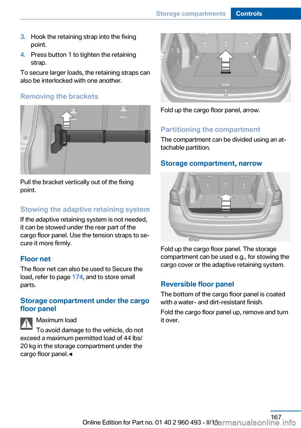
Fold up the cargo floor panel, arrow.
Partitioning the compartment The compartment can be divided using an at‐
tachable partition.
Storage compartment, narrow
Fold up the cargo floor panel. The storage
compartment can be used e.g., for stowing the
cargo cover or the adaptive retaining system.
Reversible floor panel
The bottom of the cargo floor panel is coated
with a water- and dirt-resistant finish.
Fold the cargo floor panel up, remove and turn
it over.
Seite 167Storage compartmentsControls167
Online Edition for Part no. 01 40 2 960 493 - II/15
Page 177 of 255
LoadingVehicle features and options
This chapter describes all standard, country-
specific and optional features offered with the
series. It also describes features that are not
necessarily available in your car, e. g., due to
the selected options or country versions. This
also applies to safety-related functions and
systems. The respectively applicable country
provisions must be observed when using the
respective features and systems.
Hints Overloading the vehicle
To avoid exceeding the approved ca‐
pacity of the tires, never overload the vehicle.
Overloading can lead to overheating and in‐
creases the rate at which damage develops in‐
side the tires. This could result in a sudden
loss of tire inflation pressure.◀
No fluids in the cargo area
Make sure that fluids do not leak into the
cargo area; otherwise, the vehicle may be dam‐
aged.◀
Heavy and hard objects
Do not stow any heavy and hard objects
in the car's interior without securing them; oth‐
erwise, they may present a danger to occu‐
pants, e.g., during braking and evasive maneu‐
vers.◀
Determining the load limit1.Locate the following statement on your ve‐
hicle’s placard:▷The combined weight of occupants
and cargo should never exceed XXX kg
or YYY lbs. Otherwise, damage to thevehicle and unstable driving situations
may result.2.Determine the combined weight of the
driver and passengers that will be riding in
your vehicle.3.Subtract the combined weight of the driver
and passengers from XXX kilograms or
YYY pounds.4.The resulting figure equals the available
amount of cargo and luggage load ca‐
pacity.
For example, if the YYY amount equals
1,000 lbs and there will be four 150 lbs
passengers in your vehicle, the amount of
available cargo and luggage load capacity
is 400 lbs: 1,000 lbs minus 600 lbs =
400 lbs.5.Determine the combined weight of lug‐
gage and cargo being loaded on the vehi‐
cle. That weight may not safely exceed the
available cargo and luggage load capacity
calculated in Step 4.Seite 173LoadingDriving tips173
Online Edition for Part no. 01 40 2 960 493 - II/15
Page 178 of 255
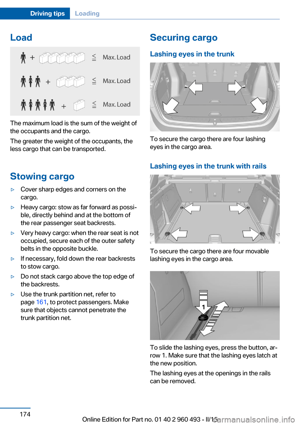
Load
The maximum load is the sum of the weight of
the occupants and the cargo.
The greater the weight of the occupants, the
less cargo that can be transported.
Stowing cargo
▷Cover sharp edges and corners on the
cargo.▷Heavy cargo: stow as far forward as possi‐
ble, directly behind and at the bottom of
the rear passenger seat backrests.▷Very heavy cargo: when the rear seat is not
occupied, secure each of the outer safety
belts in the opposite buckle.▷If necessary, fold down the rear backrests
to stow cargo.▷Do not stack cargo above the top edge of
the backrests.▷Use the trunk partition net, refer to
page 161, to protect passengers. Make
sure that objects cannot penetrate the
trunk partition net.Securing cargo
Lashing eyes in the trunk
To secure the cargo there are four lashing
eyes in the cargo area.
Lashing eyes in the trunk with rails
To secure the cargo there are four movable
lashing eyes in the cargo area.
To slide the lashing eyes, press the button, ar‐
row 1. Make sure that the lashing eyes latch at
the new position.
The lashing eyes at the openings in the rails
can be removed.
Seite 174Driving tipsLoading174
Online Edition for Part no. 01 40 2 960 493 - II/15
Page 179 of 255
Securing cargoSecuring cargo
Stow and secure the cargo as described;
otherwise it may present a danger to the occu‐
pants, e.g., during braking and evasive maneu‐
vers.◀▷Smaller and lighter items: secure with re‐
taining straps or draw straps.▷Larger and heavy objects: secure with
cargo straps.
Attach the cargo straps, retaining straps or
draw straps to the lashing eyes in the trunk.
Roof-mounted luggage rack NoteInstallation only possible with roof rack.
Roof racks are available as special accessories.
Securing Follow the installation instructions of the roof
rack.
Loading
Be sure that adequate clearance is maintained
for tilting and opening the glass sunroof.
Because roof racks raise the vehicle's center
of gravity when loaded, they have a major ef‐
fect on vehicle handling and steering re‐
sponse.
Therefore, note the following when loading
and driving:
▷Do not exceed the approved roof/axle
loads and the approved gross vehicle
weight.▷Distribute the roof load uniformly.▷The roof load should not extend past the
loading area.▷Always place the heaviest pieces on the
bottom.▷Secure the roof luggage firmly, e.g., tie
with ratchet straps.▷Do not let objects project into the opening
path of the tailgate.▷Drive cautiously and avoid sudden acceler‐
ation and braking maneuvers. Take corners
gently.Seite 175LoadingDriving tips175
Online Edition for Part no. 01 40 2 960 493 - II/15
Page 185 of 255
prox. 50 km/h to 100 mph, approx. 160 km/h, if
the following conditions are met:▷Accelerator pedal and brake pedal are not
operated.▷The selector lever is in selector lever posi‐
tion D.▷Engine and transmission are at operating
temperature.
The driving status Coast can be influenced
with the shift paddles.
Display Display in the instrument cluster
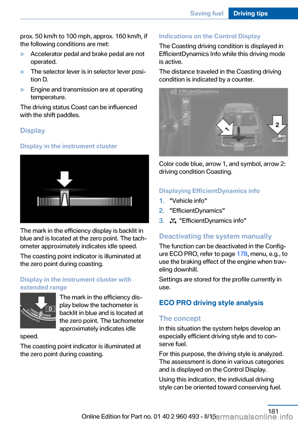
The mark in the efficiency display is backlit in
blue and is located at the zero point. The tach‐
ometer approximately indicates idle speed.
The coasting point indicator is illuminated at
the zero point during coasting.
Display in the instrument cluster with
extended range
The mark in the efficiency dis‐
play below the tachometer is
backlit in blue and is located at
the zero point. The tachometer
approximately indicates idle
speed.
The coasting point indicator is illuminated at
the zero point during coasting.
Indications on the Control Display
The Coasting driving condition is displayed in
EfficientDynamics Info while this driving mode
is active.
The distance traveled in the Coasting driving
condition is indicated by a counter.
Color code blue, arrow 1, and symbol, arrow 2:
driving condition Coasting.
Displaying EfficientDynamics info
1."Vehicle info"2."EfficientDynamics"3. "EfficientDynamics info"
Deactivating the system manually The function can be deactivated in the Config‐
ure ECO PRO, refer to page 178, menu, e.g., to
use the braking effect of the engine when trav‐
eling downhill.
Settings are stored for the profile currently in
use.
ECO PRO driving style analysis
The concept
In this situation the system helps develop an
especially efficient driving style and to con‐
serve fuel.
For this purpose, the driving style is analyzed.
The assessment is done in various categories
and is displayed on the Control Display.
Using this indication, the individual driving
style can be oriented toward conserving fuel.
Seite 181Saving fuelDriving tips181
Online Edition for Part no. 01 40 2 960 493 - II/15
Page 201 of 255
sudden tire failure. The grade C corresponds
to a level of performance which all passenger
car tires must meet under the Federal Motor
Vehicle Safety Standard No. 109. Grades Band
A represent higher levels of performance on
the laboratory test wheel than the minimum re‐
quired by law.
Temperature grade for this tire
The temperature grade for this tire is es‐
tablished for a tire that is properly inflated and
not overloaded. Excessive speed, underinfla‐
tion, or excessive loading, either separately or
in combination, can cause heat buildup and
possible tire failure.
If necessary, have the vehicle towed.◀
RSC – Run-flat tires
Run-flat tires, refer to page 199, are labeled
with a circular symbol containing the letters
RSC marked on the sidewall.
M+S
Winter and all-season tires with better cold
weather performance than summer tires.
Tire treadSummer tires
Do not drive with a tire tread depth of less than
0.12 in/3 mm.
There is an increased danger of hydroplaning if
the tire tread depth is less than 0.12 in/3 mm.
Winter tires
Do not drive with a tire tread depth of less than
0.16 in/4 mm.
Below a tread depth of 0.16 in/4 mm, tires are
less suitable for winter operation.Minimum tread depth
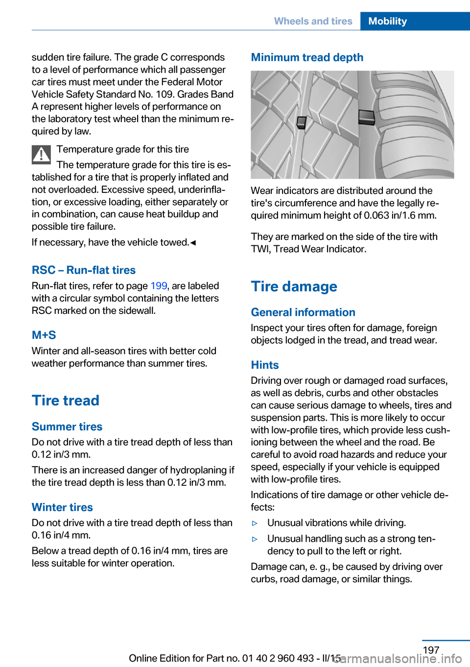
Wear indicators are distributed around the
tire's circumference and have the legally re‐
quired minimum height of 0.063 in/1.6 mm.
They are marked on the side of the tire with
TWI, Tread Wear Indicator.
Tire damage
General information
Inspect your tires often for damage, foreign
objects lodged in the tread, and tread wear.
Hints
Driving over rough or damaged road surfaces,
as well as debris, curbs and other obstacles
can cause serious damage to wheels, tires and
suspension parts. This is more likely to occur
with low-profile tires, which provide less cush‐
ioning between the wheel and the road. Be
careful to avoid road hazards and reduce your
speed, especially if your vehicle is equipped
with low-profile tires.
Indications of tire damage or other vehicle de‐
fects:
▷Unusual vibrations while driving.▷Unusual handling such as a strong ten‐
dency to pull to the left or right.
Damage can, e. g., be caused by driving over
curbs, road damage, or similar things.
Seite 197Wheels and tiresMobility197
Online Edition for Part no. 01 40 2 960 493 - II/15
Page 202 of 255
In case of tire damage
If there are indications of tire damage, re‐
duce your speed immediately and have the
rims and tires checked right away; otherwise,
there is the increased risk of an accident.
Drive carefully to the nearest service center. If
necessary, have the vehicle towed or trans‐
ported there. Otherwise, tire damage can be‐
come life threatening for vehicle occupants
and also other traffic.◀
Repair of tire damage
For safety reasons, the manufacturer of
your vehicle recommends that you do not have
damaged tires repaired; they should be re‐
placed. Otherwise, damage can occur as a re‐
sult.◀
Changing wheels and tires
Mounting Information on mounting tires
Have mounting and balancing performed
only by a service center.
If work is not carried out properly, there is a
danger of subsequent damage and related
safety hazards.◀
Wheel and tire combination
You can ask the service center about the right
wheel/tire combination and wheel rim versions
for the vehicle.
Incorrect wheel and tire combinations impair
the function of a variety of systems such as
ABS or DSC.
To maintain good handling and vehicle re‐
sponse, use only tires with a single tread con‐
figuration from a single manufacturer.
Following tire damage, have the original wheel
and tire combination remounted on the vehicle
as soon as possible.Approved wheels and tires
You should only use wheels and tires
that have been approved by the vehicle manu‐
facturer for your vehicle type; otherwise, e.g.,
despite having the same official size ratings,
variations can lead to chassis contact and with
it, the risk of severe accidents
The manufacturer of your vehicle cannot eval‐
uate non-approved wheels and tires to deter‐
mine if they are suited for use, and therefore
cannot guarantee the operating safety of the
vehicle.◀
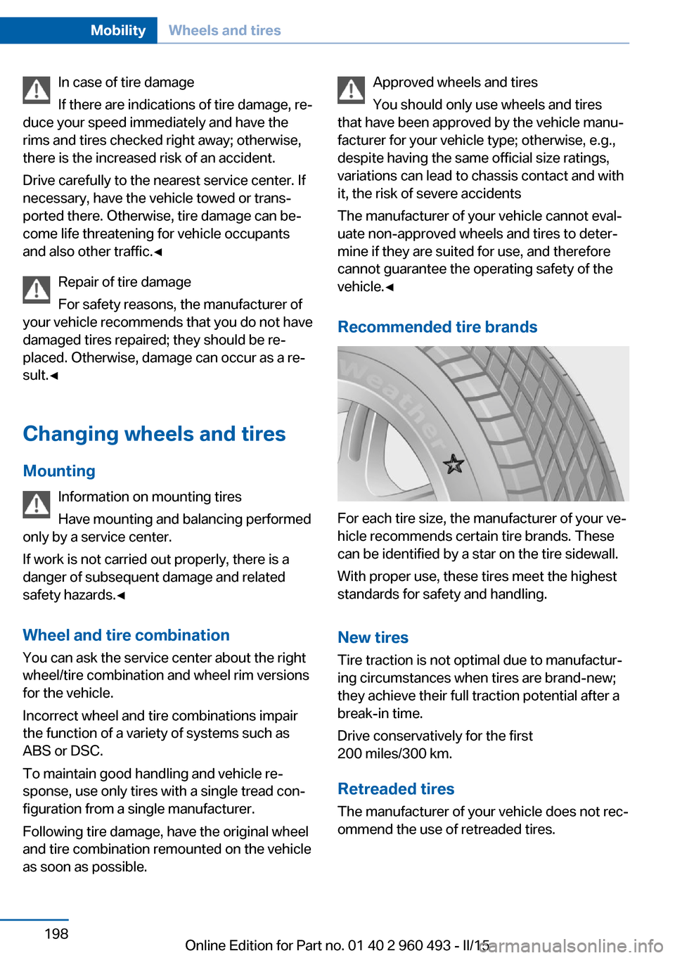
Recommended tire brands
For each tire size, the manufacturer of your ve‐
hicle recommends certain tire brands. These
can be identified by a star on the tire sidewall.
With proper use, these tires meet the highest
standards for safety and handling.
New tires Tire traction is not optimal due to manufactur‐
ing circumstances when tires are brand-new;
they achieve their full traction potential after a
break-in time.
Drive conservatively for the first
200 miles/300 km.
Retreaded tires
The manufacturer of your vehicle does not rec‐
ommend the use of retreaded tires.
Seite 198MobilityWheels and tires198
Online Edition for Part no. 01 40 2 960 493 - II/15
Page 204 of 255
into the tires, which seals the damage from the
inside.
The compressor can be used to check the tire
inflation pressure.
Hints▷Follow the instructions on using the Mobi‐
lity System found on the compressor and
sealant container.▷Use of the Mobility System may be ineffec‐
tive if the tire puncture measures approx.
1/8 in/4 mm or more.▷Contact the nearest service center if the
tire cannot be made drivable.▷If possible, do not remove foreign bodies
that have penetrated the tire.▷Pull the speed limit sticker off the sealant
container and apply it to the steering
wheel.▷The use of a sealant can damage the TPM
wheel electronics. In this case, have the
electronics checked at the next opportu‐
nity and have them replaced if needed.
Enclosed areas
Do not let the engine run in enclosed
areas, since breathing in exhaust fumes may
lead to loss of consciousness and death. The
exhaust gases contain carbon monoxide, an
odorless and colorless but highly toxic gas.◀
Storage The Mobility System is located under the
cargo floor panel.
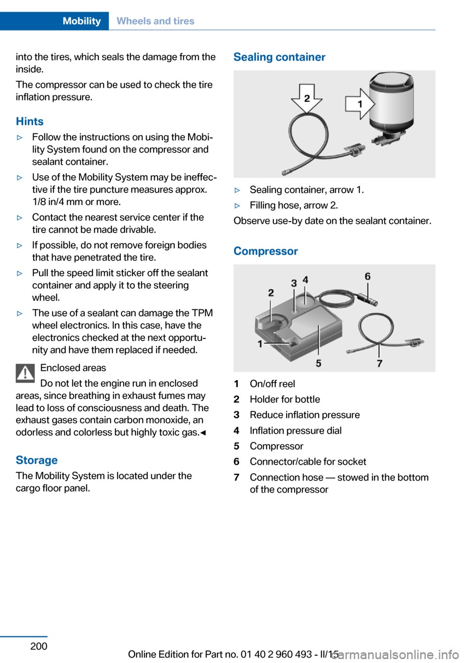
Sealing container▷Sealing container, arrow 1.▷Filling hose, arrow 2.
Observe use-by date on the sealant container.
Compressor
1On/off reel2Holder for bottle3Reduce inflation pressure4Inflation pressure dial5Compressor6Connector/cable for socket7Connection hose — stowed in the bottom
of the compressorSeite 200MobilityWheels and tires200
Online Edition for Part no. 01 40 2 960 493 - II/15
Page 206 of 255
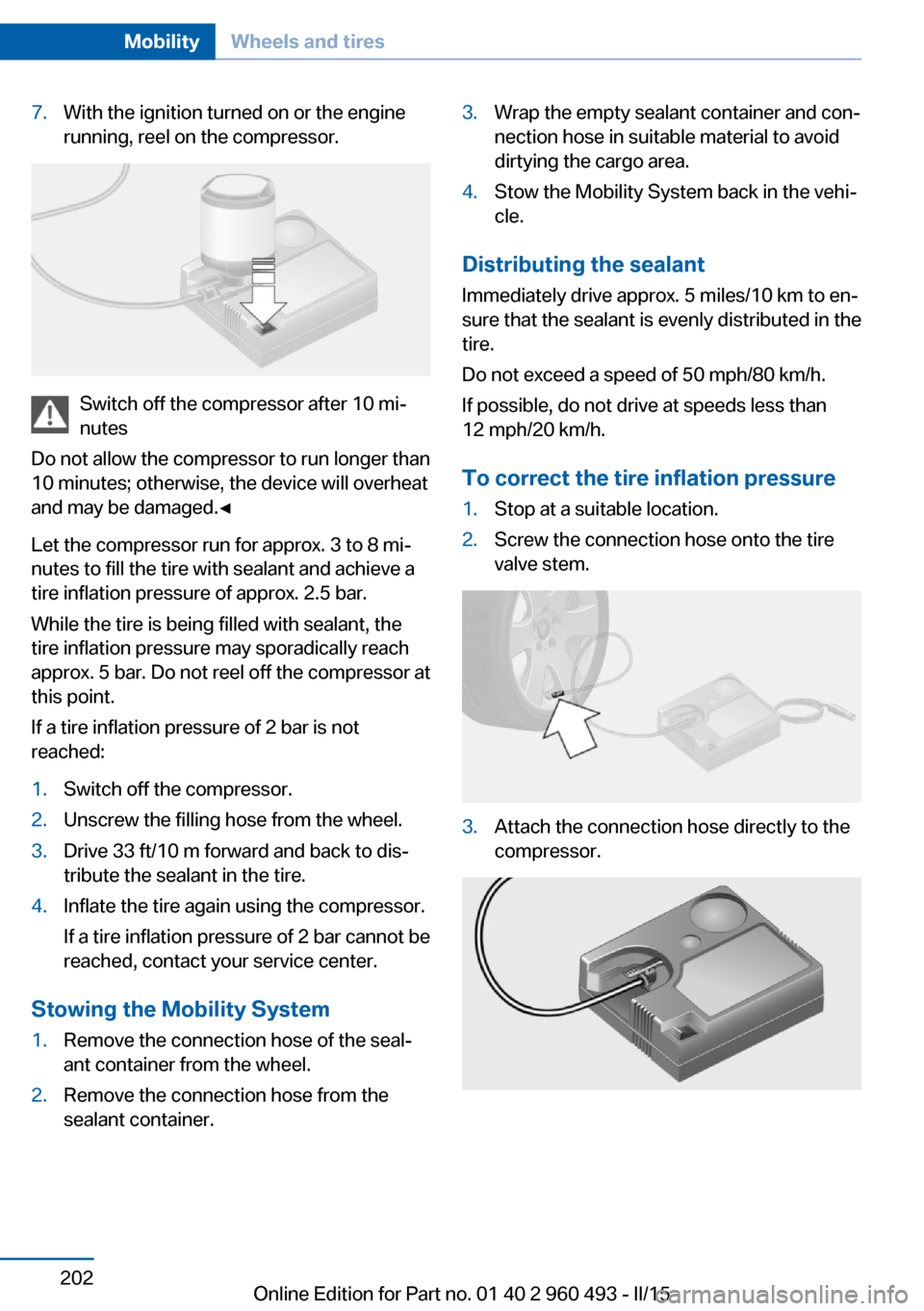
7.With the ignition turned on or the engine
running, reel on the compressor.
Switch off the compressor after 10 mi‐
nutes
Do not allow the compressor to run longer than
10 minutes; otherwise, the device will overheat
and may be damaged.◀
Let the compressor run for approx. 3 to 8 mi‐
nutes to fill the tire with sealant and achieve a
tire inflation pressure of approx. 2.5 bar.
While the tire is being filled with sealant, the
tire inflation pressure may sporadically reach
approx. 5 bar. Do not reel off the compressor at
this point.
If a tire inflation pressure of 2 bar is not
reached:
1.Switch off the compressor.2.Unscrew the filling hose from the wheel.3.Drive 33 ft/10 m forward and back to dis‐
tribute the sealant in the tire.4.Inflate the tire again using the compressor.
If a tire inflation pressure of 2 bar cannot be
reached, contact your service center.
Stowing the Mobility System
1.Remove the connection hose of the seal‐
ant container from the wheel.2.Remove the connection hose from the
sealant container.3.Wrap the empty sealant container and con‐
nection hose in suitable material to avoid
dirtying the cargo area.4.Stow the Mobility System back in the vehi‐
cle.
Distributing the sealant
Immediately drive approx. 5 miles/10 km to en‐
sure that the sealant is evenly distributed in the
tire.
Do not exceed a speed of 50 mph/80 km/h.
If possible, do not drive at speeds less than
12 mph/20 km/h.
To correct the tire inflation pressure
1.Stop at a suitable location.2.Screw the connection hose onto the tire
valve stem.3.Attach the connection hose directly to the
compressor.Seite 202MobilityWheels and tires202
Online Edition for Part no. 01 40 2 960 493 - II/15