Alternator wiring BMW 318i 1992 E36 Workshop Manual
[x] Cancel search | Manufacturer: BMW, Model Year: 1992, Model line: 318i, Model: BMW 318i 1992 E36Pages: 759
Page 3 of 759
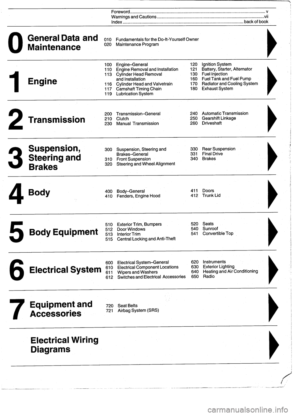
General
Data
and
010
FundamentalsfortheDo-lt-YourselfOwner
Maintenance
020
Maintenance
Program
Engine
Transmission
Suspension,
Steering
and
Brakes
4
Body
100
Engine-General
110
Engine
Removal
and
Installation
113
Cylinder
Head
Removal
and
Installation
116
Cylinder
Head
and
Valvetrain
117
Camshaft
Timing
Chain
119
Lubrication
System
200
Transmission-General
210
Clutch
230
Manual
Transmission
510
Exterior
Trim,
Bumpers
520
Seats
Bo
y
Equipment
512
DoorWTdws
540
nr
t
513
InteriorTrim
541
Convertible
Top
515
Central
Locking
and
Anti-Theft
600
Electrical
System-General
620
Instruments
Electrical
S
stem
610
Electrical
Component
Locations
630
Exterior
Lighting
611
Wipers
and
Washers
640
Heating
and
Air
Conditioning
6
612
Switches
and
Electrical
Accessories
650
Radio
Equipment
and
720
SeatBelts
Accessories
721
Airbag
System
(SRS)
Electrical
Wiring
Diagrams
Foreword
.
...
.
.
.
..................
.
.
.
.....
.
............
.
...
.
.
.
.
.
................
.
.
.
.....
.
......
.
................
.
.
.
.....
v
Warnings
and
Cautions
.....
.
...
.
.
.
.
.
..........
.
...
.
.
.
.
.
......
.
.........
.
.
.
...
.
.
.
......
.
.
.
.
.
............
.
.
.
.
.
.
.vii
Index
..............
.
.
.
.....
.
............
.
...
.
.
.
.
.
........
.
...
.
.
.
.
.
.......
.
......
.
...
.
.
.
.
.
.
.
........
.
.
.
..
back
of
book
300
Suspension,
Steering
and
330
RearSuspension
Brakes-General
331
Final
Drive
310
Front
Suspension
340
Brakes
320
Steering
and
Wheel
Alignment
400
Body-General
411
Doors
410
Fenders,
Engine
Hood
412
Trunk
Lid
120
Ignition
System
121
Battery,Starter,
Alternator
130
Fue¡
Injection
160
Fuel
Tank
and
Fuel
Pump
170
Radiator
and
Cooling
System180
Exhaust
System
240
Automatic
Transmission
250
Gearshift
Linkage
260
Driveshaft
Page 61 of 759
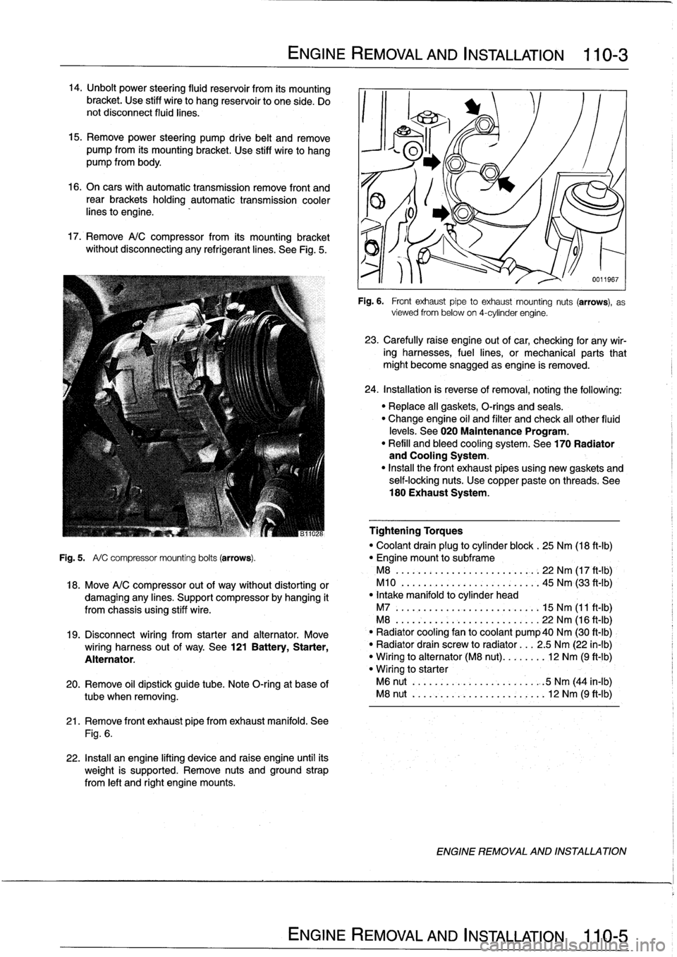
14
.
Unbolt
power
steering
fluid
reservoir
from
íts
mounting
bracket
.
Use
stiff
wire
to
hang
reservoir
to
one
side
.
Do
not
disconnect
fluid
lines
.
15
.
Remove
power
steering
pump
drive
belt
and
remove
pump
from
its
mounting
bracket
.
Use
stiff
wire
to
hang
pump
from
body
.
16
.
On
cars
with
automatic
transmission
remove
front
and
rear
brackets
holding
automatic
transmission
cooler
linesto
engine
.
17
.
Remove
A/C
compressor
from
its
mounting
bracket
without
disconnecting
any
refrigerantlines
.
See
Fig
.
5
.
ENGINE
REMOVAL
AND
INSTALLATION
110-
3
21
.
Remove
front
exhaust
pipefrom
exhaust
manifold
.
See
Fig
.
6
.
22
.
Install
an
engine
lifting
device
and
raise
engine
until
its
weight
is
supported
.
Remove
nuts
and
ground
strap
from
left
and
right
engine
mounts
.
0011967
Fig
.
6
.
Front
exhaustpipe
to
exhaust
mounting
nuts
(arrows),
as
viewed
from
below
on
4-cylinder
engine
.
23
.
Carefully
raíse
engine
out
of
car,
checking
for
any
wir-
ing
harnesses,
fuel
lines,
or
mechanical
parts
that
might
become
snagged
as
engine
is
removed
.
24
.
Installation
is
reverse
of
removal,
noting
the
following
:
"
Replace
all
gaskets,
O-rings
and
seals
.
"
Change
engine
oil
and
filter
and
check
al¡
other
fluid
levels
.
See020
Maintenance
Program
.
"
Refill
and
bleed
cooling
system
.
See
170
Radiator
and
Cooling
System
.
"
Insta¡¡
the
front
exhaust
pipes
using
new
gaskets
and
self-locking
nuts
.
Use
copper
pasteon
threads
.
See
180
Exhaust
System
.
Tightening
Torques
"
Coolant
drain
plug
to
cylinder
block
.
25
Nm
(18
ft-Ib)
Fig
.
5
.
A/
C
compressor
mounting
bolts
(arrows)
.
"
Engine
mount
to
subframe
M8
......:...
..
..
..
......,:..
22
Nm
(17
ft
-
1b)
,
18
.
Move
A/C
compressor
out
of
way
without
distorting
or
M10
.
...
.
..
...
.
.
...........
45
Nm
(33
ft'-Ib)
damaging
any
lines
.
Support
compressor
by
hanging
it
"
Intake
manifold
to
cylinder
head
from
chassis
using
stiff
wire
.
M7
.....
.
..
...
..
..
...........
15
Nm
(11
ft-Ib)
M8
...
.
.
.
..
..
...
..
...........
22
Nm
(16
ft-Ib)
19
.
Disconnect
wiring
from
starter
and
alternator
.
Move
`
"
Radiator
cooling
fan
to
coolant
pump40
Nm
(30
ft-Ib)
wiring
harness
out
of
way
.
See
121
Battery,
Starter,
"
Radiator
drain
screw
to
radiator
...
2
.5
Nm
(22
in-lb)
Alternator
.
"
Wiring
to
alternator
(M8
nut)
........
12
Nm
(9
ft-1b)
"
Wiring
to
starter
20
.
Remove
oil
dipstick
guide
tube
.
Note
O-ring
at
base
of
M6
nut
..
.
..
..
...
..
...........
.
:5
Nm
(44
in-lb)
tube
when
removing
.
M8
nut
..
.
..
..
...
..
............
12
Nm
(9
ft-Ib)
ENGINE
REMOVAL
AND
INSTALLATION
Page 65 of 759
22
.
Move
A/C
compressor
out
of
the
way
without
distorting
26
.
Carefully
raise
engine
out
ofcar,
checking
for
any
wir-
or
damaging
any
lines
.
Support
compressor
by
hanging
ing,fuel
lines,
or
mechanical
parts
that
might
become
it
from
chassis
using
stiff
wire
.
snagged
as
engine
is
removed
.
23
.
Disconnect
wiring
from
starter
and
alternator
.
Move
27
.
Installation
is
reverse
of
removal,
noting
the
following
:
wiring
harness
out
of
the
way
.
See
121
Battery,
Start-
Replace
al¡
gaskets,
O-rings
and
seals
.
er,
Alternator
.
"
Change
engine
oil
and
filter
and
check
all
other
fluid
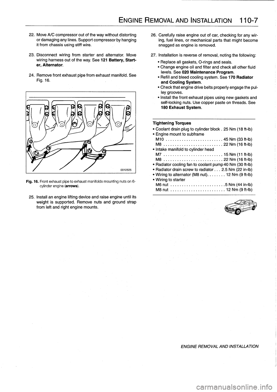
24
.
Remove
Fontexhaust
pipe
fromexhaust
manifold
.
See
levels
.
See
020
Maintenance
Program
.
"
Refill
and
bleed
cooling
system
.
See
170
Radiator
Fig
.
16
.
and
Cooling
System
.
"
Check
that
engine
drivebelts
properly
engage
the
pul-
ley
grooves
.
"
Install
the
Font
exhaust
pipesusing
new
gaskets
and
seif-locking
nuts
.
Use
copper
paste
on
threads
.
See
180
Exhaust
System
.
0012525
Fig
.
16
.
Front
exhaust
pipeto
exhaust
manifolds
mounting
nuts
on
6-
cylinder
engine
(arrows)
.
25
.
Install
an
engine
lifting
device
and
raise
engine
until
its
weight
is
supported
.
Remove
nuts
and
ground
strap
from
left
and
right
engine
mounts
.
ENGINE
REMOVAL
AND
INSTALLATION
110-
7
Tightening
Torques
"
Coolant
drain
plug
to
cylinder
block
.
25
Nm
(18
ft-Ib)
"
Engine
mount
to
subframe
M10
..
.
.
.
...
..............
..
.
45
Nm
(33
ft-Ib)
M8
..
..
.
..
................
...
22
Nm
(16
ft-Ib)
"
Intake
manifold
to
cylinder
head
M7
..
..
..
...
................
.
15
Nm
(11
ft-Ib)
M8
...
.
..
...
................
.
22
Nm
(16
ft-Ib)
"
Radiator
cooling
fan
to
coolant
pump40
Nm
(30
ft-Ib)
"
Radiator
drain
screw
to
radíator
...
2
.5
Nm
(22
in-lb)
"
Wiring
to
alternator
(M8
nut)
........
12
Nm
(9
ft-Ib)
"
Wiring
to
starter
M6
nut
.
..
...
..................
5
Nm
(44
in-lb)
M8
nut
.....
..
.
.
.
.
.............
12
Nm
(9
ft-Ib)
ENGINE
REMOVAL
AND
INSTALLATION
Page 70 of 759
113-4
CYLINDER
HEAD
REMOVAL
AND
INSTALLATION
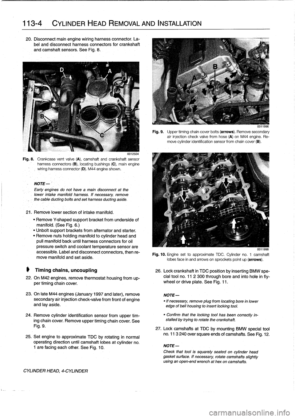
20
.
Disconnect
main
engine
wiring
harness
connector
.
La-
bel
and
disconnect
harness
connectors
for
crankshaft
and
camshaft
sensors
.
See
Fig
.
8
.
0012504
Fig
..
Crankcase
vent
valve
(A),
camshaft
and
crankshaft
sensor
harness
connectors
(B),
locating
bushings
(C),
main
engine
wiring
harnessconnector
(D)
.
M44
engine
shown
.
NOTE-
Early
engines
do
not
havea
maín
disconnect
at
the
lower
intake
manifold
harness
.
lf
necessary,
remove
the
cable
ducting
bolts
and
set
harness
ducting
aside
.
21
.
Remové
lower
section
of
intake
manifold
.
"
Remove
Y
shaped
supportbracket
from
underside
of
manifold
.
(See
Fig
.
6
.)
"
Unbolt
support
brackets
from
alternator
and
starter
.
"
Remove
nuts
holding
manifold
to
cylinder
head
and
pull
manifold
back
until
harness
connectors
for
oil
pressure
switch
and
coolant
temperature
sensorare
accessible
.
Label
and
disconnect
connectors,
then
re-
move
manifold
and
set
aside
.
Timing
chains,
uncoupling
26
.
Lock
crankshaft
in
TDC
position
by
insertíng
BMW
spe-
22
.
On
M42
engines,
remove
thermostat
housing
from
up-
cial
tool
no
.
11
2
300
through
bore
and
into
hole
infly-
per
timing
chaincover
.
wheel
or
driveplate
.
See
Fig
.
11
.
23
.
On
late
M44
engines
(January
1997
and
later),
remove
NOTE-
secondary
air
injection
check-valve
from
front
of
engine
"
If
necessary,
remove
plug
from
locating
bore
in
lower
and
lay
aside
.
edge
of
bell
housing
to
insert
locking
tool
.
24
.
Remove
cylinder
identification
sensor
from
upper
tim-
ing
chaincover
.
Remove
upper
timing
chaincover
.
See
Fig
.
9
.
25
.
Set
engine
to
approximate
TDC
by
rotating
in
normal
operating
direction
until
camshaft
lobes
at
cylinder
no
.
1
are
facing
each
other
.
See
Fig
.
10
.
CYLINDER
HEAD,
4-CYLINDER
Fig
.
9
.
Upper
timing
chain
cover
bolts
(arrows)
.
Remove
secondary
air
injection
check
valve
fromhose
(A)
on
M44
engine
.
Re-
move
cylinder
identification
sensor
from
chaincover
(B)
.
0011998
Fig
.
10
.
Engine
set
to
approximate
TDC
.
Cylinder
no
.
1
camshaft
lobes
face
in
and
arrows
on
sprockets
poínt
up
(arrows)
.
"
Confirm
that
the
locking
tool
has
been
correctly
in-
stalled
by
trying
to
rotate
the
crankshaft
.
27
.
Lock
camshafts
at
TDC
by
mounting
BMW
specíal
tool
no
.
113
240
over
square
ends
of
camshafts
.
See
Fig
.
12
.
NOTE-
Check
that
tool
is
squarely
seated
on
cylinder
head
gasket
surface
.
If
necessary,
rotate
camshafts
slightly
using
an
open-end
wrench
at
hex
oncamshafts
.
Page 120 of 759
119-
6
LUBRICATION
SYSTEM
17
.
Raise
engine
as
much
as
possible
.
Check
carefully
for
22
.
Installation
is
reverse
of
removal
.
obstructions,
wiring
harness
clearance
and
pinched
hoses
or
lines
as
engine
is
raised
.
"
When
installing
oil
pan,
apply
a
b
d
of
non-hardening
sealing
compound
(3-Bond
1209
0
or
equivalent)
to
18
.
Remove
oil
pan
mounting
bolts
and
lower
oil
pan
to
front
and
rear
end
cover
seam
areas
on
block
.
subframe
crossmember
.
"
Position
oil
pump
pickup
tube
and
oil
pan
onto
block
and
install
pickup
tube
using
a
new
gasket
.
"
Be
sure
tab
on
gasket
faces
down
towards
intake
of
NOTE-
pickup
tube
.
If
the
oil
pan
does
not
separate
easily
from
the
engine
"
Tightenforward
oil
pan
screws
first,
then
tighten
rear
.
cylinder
block,
afew
taps
with
arubber
mallet
should
"
Fill
engine
with
oil
as
described
in
020
Maintenance
break
it
free
.
Do
not
pry
the
oil
pan
loose
.
Program
.
"
After
adding
engine
oil,
start
and
run
engine
.
Raise
en-
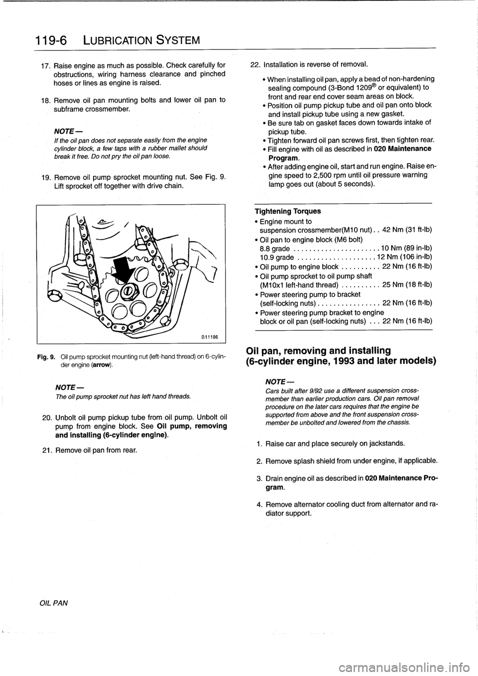
19
.
Remove
oil
pump
sprocket
mounting
nut
.
See
Fig
.
9
.
gine
speed
to
2,500
rpm
until
oil
pressure
warning
Lift
sprocket
off
together
with
drive
chain
.
lampgoes
out(about
5seconds)
.
Fig
.
9
.
Oil
pump
sprocket
mounting
nut
(left-hand
thread)
on
6-cylin-
OII
pan,
removing
and
installing
derengine(arrow)
.
(6-cylinder
engine,
1993
and
later
modeis)
NOTE-
The
oíl
pump
sprocket
nut
has
left
hand
threads
.
20
.
Unbolt
oil
pump
pickup
tubefrom
oil
pump
.
Unbolt
oil
pump
from
engine
block
.
See
Oil
pump,
removing
and
installing
(6-cylinder
engine)
.
21
.
Remove
oil
pan
from
rear
.
Tightening
Torques
"
Engine
mount
to
suspension
crossmember(M10
nut)
..
42
Nm
(31
ft-Ib)
"
Oil
pan
to
engine
block
(M6
bolt)
8
.8
grade
....
..
.
...
...
.
........
10
Nm
(89
in-lb)
10
.9
grade
.
.
..
.
..
...
.
.
.
.
.
.....
12
Nm
(106
in-lb)
"
Oil
pump
to
engine
block
.
...
...
.
..
22
Nm
(16
ft-Ib)
"
Oil
pump
sprocket
to
oil
pump
shaft
(M1
0x1
left-hand
thread)
...
..
.
.
..
.
25
Nm
(18
ft-Ib)
"
Power
steering
pump
to
bracket
(self-locking
nuts)
.....
.
....
..
.
...
22
Nm
(16
ft-lb)
"
Power
steering
pump
bracket
to
engine
block
or
oil
pan
(self-locking
nuts)
.
..
22
Nm
(16
ft-Ib)
NOTE-
Cars
built
after
9/92
use
a
different
suspension
cross-
member
¡han
earfier
productíon
cars
.
Oil
pan
removal
procedure
on
the
later
cars
requíres
that
the
engine
be
supported
from
aboye
and
the
front
suspension
cross-
member
be
unbolted
and
loweredfrom
the
chassis
.
1
.
Raisecar
and
place
securely
on
jackstands
.
2
.
Remove
splash
shield
fromunder
engine,
if
applicable
.
3
.
Drain
engine
oil
as
descríbed
in
020
Maintenance
Pro-
gram
.
4
.
Remove
alternator
cooling
duct
from
alternator
and
ra-
diator
support
.
Page 140 of 759
121-
4
BATTERY,
STARTER,
ALTERNATOR
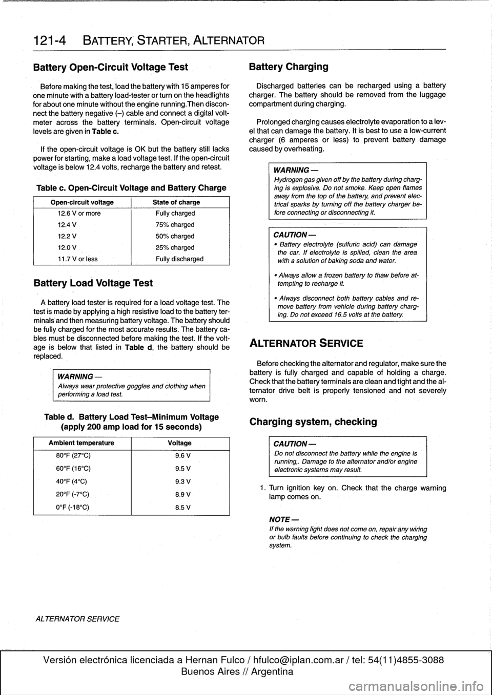
BatteryOpen-Circuit
Voltage
Test
Battery
Charging
Before
making
the
test,
load
the
battery
with
15
amperes
for
Discharged
batteries
can
be
recharged
using
a
battery
one
minute
with
a
batteryload-tester
or
turn
on
the
headlights
charger
.
The
battery
should
be
removed
from
the
luggage
for
about
one
minute
without
the
engine
running
.Then
discon-
compartment
during
charging
.
nect
the
battery
negative
(-)
cable
and
connect
a
digital
volt-
meter
acrossthe
battery
terminals
.
Open-circuit
voltage
Prolonged
charging
causes
electrolyte
evaporation
to
a
lev
levels
are
given
in
Table
c
.
el
that
can
damage
the
battery
.
Itis
bestto
use
a
low-current
charger
(6
amperes
or
less)
to
prevent
battery
damage
If
the
open-circuit
voltage
ís
OK
butthe
battery
still
lacks
caused
by
overheating
.
power
for
starting,
make
a
load
voltage
test
.
If
the
open-circuit
voltage
is
below
12
.4
volts,
recharge
the
battery
and
retest
.
WARNING
-
Hydrogen
gas
given
off
by
the
battery
duringcharg-
Table
c
.
Open-Circuit
Voltage
and
Battery
Charge
ing
is
explosive
.
Do
not
smoke
.
Keep
open
llames
away
from
the
top
of
the
battery,
and
prevent
elec
Open-circuit
voltage
State
of
charge
trical
sparks
by
turning
offthe
battery
charger
be-
12
.6
V
or
more
Fully
charged
fore
connecting
or
disconnecting
it
.
12
.4
V
1
75%
charged
12
.2
V
50%
charged
CAUTION-
12
.0
V
25%
charged
"
Battery
electrolyte
(sulfuric
acid)
can
damage
the
car
.
If
electrolyte
isspilled,
clean
the
area
11
.7
V
or
less
Fully
discharged
with
a
solution
of
baking
soda
and
water
.
Battery
Load
Voltage
Test
A
battery
load
tester
is
required
for
a
load
voltage
test
.
The
-
Always
disconnect
both
battery
cables
and
re-
test
is
made
by
applying
a
high
resistive
load
to
the
battery
ter-
move
battery
from
vehicle
during
battery
charg-
ing
.
Do
not
exceed
16
.5volts
at
the
battery
.
minals
and
then
measuring
battery
voltage
.
The
battery
should
be
fully
charged
for
the
most
accurate
results
.
The
battery
ca-
bles
mustbe
disconnected
before
making
the
test
.
If
the
volt-
ALTERNATOR
$ERVICE
age
is
below
that
listed
in
Table
d,
the
battery
should
be
replaced
.
WARNING
-
Always
wear
protective
goggles
and
clothing
when
performing
aload
test
.
Table
d
.
Battery
Load
Test-Minimum
Voltage
(apply
200
amp
load
for
15
seconds)
Ambient
temperature
Voltage
80°F
(27°C)
9
.6
V
60°F
(16°C)
9
.5
V
40°F
(4°C)
9
.3
V
20°F
(-7°C)
8
.9
V
0°F
(-18°C)
8
.5
V
ALTERNATOR
SERVICE
"
Always
allow
a
frozen
battery
to
thaw
before
at-
tempting
to
recharge
it
.
Before
checking
the
alternator
and
regulator,
make
sure
the
battery
is
fully
charged
and
capable
of
holding
acharge
.
Check
that
the
battery
terminals
are
clean
and
tight
and
the
al-
ternator
drive
belt
is
properly
tensioned
and
not
severely
worn
.
Charging
system,
checking
CAUTION-
Do
not
disconnect
the
battery
while
the
engine
is
running,
.
Damage
to
the
alternator
andlorengine
electronic
systems
may
result
.
1.
Turn
ignition
key
on
.
Check
that
the
chargewarning
lamp
comes
on
.
NOTE-
If
the
warning
light
does
not
come
on,
repair
any
wiring
or
bulb
faults
before
continuing
to
check
the
charging
system
.
Page 141 of 759
2
.
Remove
cooling
duct
or
terminal
cover
from
rear
of
al-
2
.
Remove
air
cleaner
upper
section
with
mass
air
flow
ternator
.
sensor
.
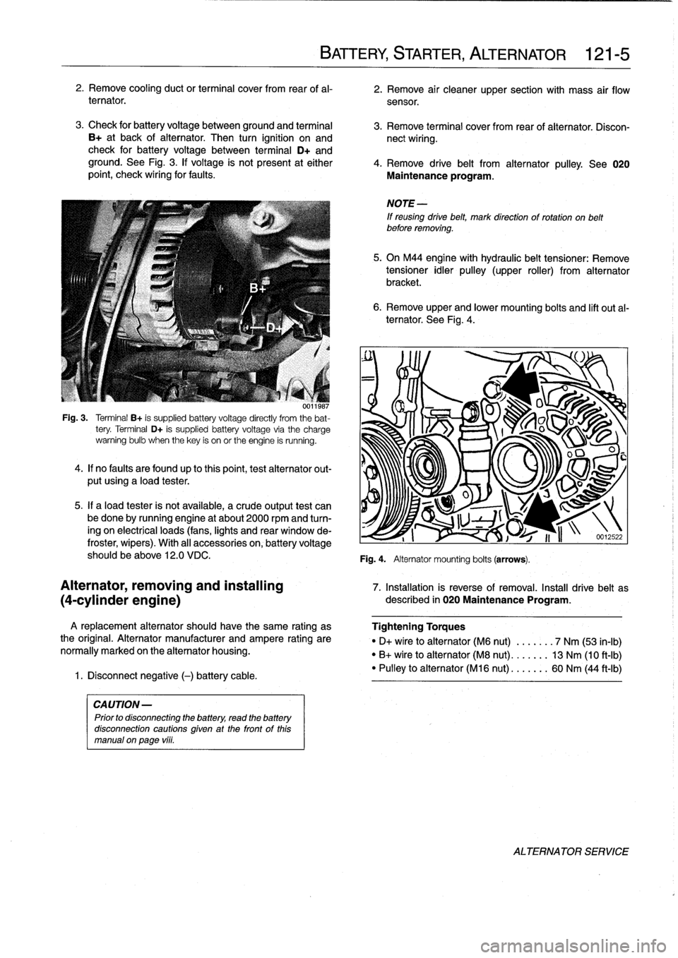
3
.
Check
for
battery
voltage
between
ground
and
terminal
3
.
Remove
terminal
cover
from
rear
of
alternator
.
Discon
B+
at
back
of
alternator
.
Then
turn
ignition
on
and
nect
wiring
.
check
for
battery
voltage
between
terminal
D+
and
ground
.
See
Fig
.
3
.
lf
voltage
is
not
present
at
either
4
.
Remove
drive
belt
from
alternator
pulley
.
See
020
point,
check
wiring
for
faults
.
Maintenance
program
.
001
¡987
Fig
.
3
.
Terminal
B+
is
supplied
battery
voltage
directly
from
the
bat-
tery
.
Terminal
D+
is
supplied
battery
voltage
via
the
charge
warning
bulb
when
thekey
is
on
or
the
engine
is
running
.
4
.
lf
no
faults
are
foundup
to
thispoint,test
alternator
out-
put
using
a
load
tester
.
5
.
If
a
load
tester
is
not
available,
a
crude
output
test
can
be
done
by
running
engine
at
about
2000
rpmand
turn-
ing
on
electrical
loads
(fans,
lights
and
rear
window
de-
froster,
wipers)
.
With
al¡
accessories
on,
battery
voltage
should
be
above
12
.0
VDC
.
A
replacement
alternator
should
have
the
same
rating
as
the
original
.
Alternator
manufacturer
and
ampere
rating
are
normally
marked
on
the
alternator
housing
.
1
.
Disconnect
negative
(-)
battery
cable
.
CAUTION-
Prior
to
disconnecting
the
battery,
read
the
battery
disconnection
cautions
given
at
the
front
of
this
manual
on
page
vi¡¡
.
BATTERY,
STARTER,
ALTERNATOR
121-
5
6
.
Remove
upper
and
lower
mounting
bolts
and
lift
out
al-
ternator
.
See
Fig
.
4
.
NOTE
-
If
reusing
drive
belt,
mark
direction
of
rotation
on
belt
before
removing
.
5
.
On
M44
engine
with
hydraulic
belt
tensioner
:
Remove
tensioner
idler
pulley
(upper
roller)
from
alternator
bracket
.
Fig
.
4
.
Alternator
mounting
bolts
(arrows)
.
O
u
J
S
v~~
U
I
1
i
n
-12
.22
Alternator,
removing
and
installing
7
.
Installation
is
reverse
of
removal
.
Install
drive
belt
as
(4-cylinder
engine)
described
in
020
Maintenance
Program
.
Tightening
Torques
"
D+
vire
to
alternator
(M6
nut)
.
...
.
.
.
7
Nm
(53
in-lb)
"
B+
wire
to
alternator
(M8
nut)
..
.
.
.
.
.
13
Nm
(10
ft-Ib)
"
Pulley
to
alternator
(M16
nut)
...
..
..
60
Nm
(44
ft-Ib)
ALTERNATOR
SERVICE
Page 142 of 759
121-
6
BATTERY
STARTER,
ALTERNATOR
Alternator,
removing
and
installing
(6-cylinder
engine)
A
replacement
alternator
should
have
the
same
rating
as
the
original
.
Alternator
manufacturer
and
ampere
rating
are
normally
marked
on
the
alternator
housing
.
1
.
Disconnect
negative
(-)
battery
cable
.
CAUTION-
Prior
to
disconnectiog
the
battery,
read
the
battery
disconnection
cautions
given
at
the
front
of
this
manual
onpage
viii
.
2
.
Remove
alternator
cooling
duct
and
air
filter
housing
assembly
from
car
.
Disconnect
wiring
from
rear
of
alter-
nator
.
3
.
Remove
radiator
cooling
fan
and
fan
shroud
.
See
170
Radiator
and
Cooling
System
.
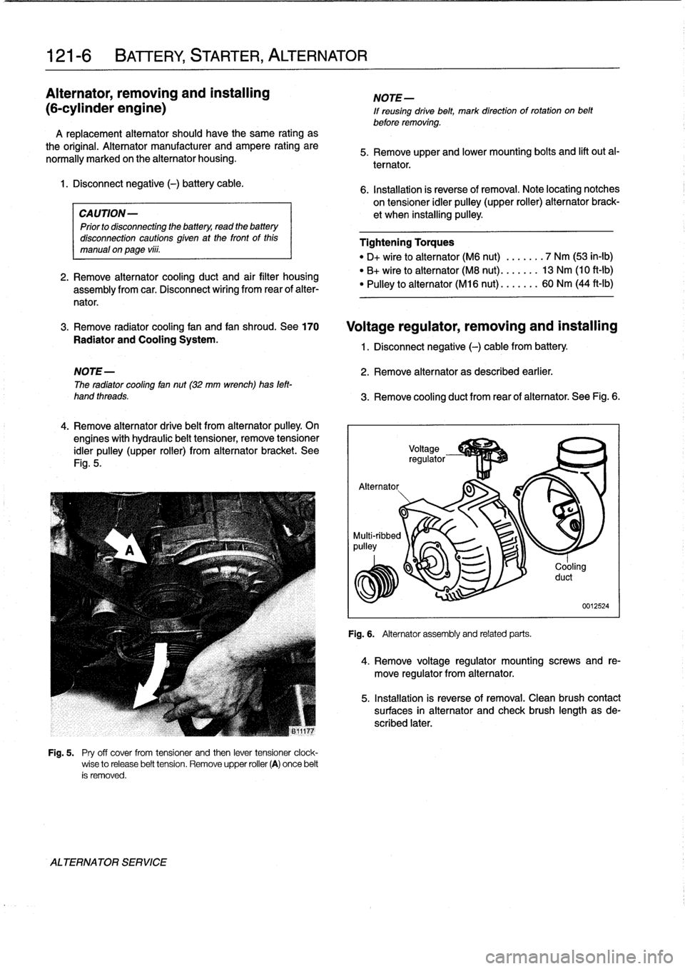
4
.
Remove
alternator
drive
belt
from
alternator
pulley
.
On
engines
with
hydraulic
belt
tensioner,
remove
tensioner
idler
pulley
(upper
roller)
from
alternator
bracket
.
See
Fig
.
5
.
ALTERNATOR
SERVICE
Fig
.
5
.
Pry
off
cover
from
tensioner
and
then
lever
tensioner
clock-
wise
to
release
belt
tension
.
Remove
upper
roller
(A)
once
belt
ís
removed
.
NOTE-
If
reusing
drive
belt,
mark
direction
of
rotation
on
belt
before
removing
.
5
.
Remove
upper
and
lower
mounting
bolts
and
lift
out
al-
ternator
.
6
.
Installation
is
reverse
of
removal
.
Note
locating
notches
on
tensioner
idler
pulley
(upper
roller)
alternator
brack-
et
when
installing
pulley
.
Tightening
Torques
"
D+
wire
to
alternator
(M6
nut)
.......
7
Nm
(53
in-lb)
"
B+
wireto
alternator
(M8
nut)
.......
13
Nm
(10
ft-Ib)
"
Pulley
to
alternator
(M16
nut)
.......
60
Nm
(44
ft-Ib)
Voltage
regulator,
removing
and
installing
1
.
Disconnect
negative
(-)
cable
from
battery
.
NOTE-
2
.
Remove
alternator
as
described
earlier
.
The
radiator
cooling
fan
nut
(32
mm
wrench)has
left-
hand
threads
.
3
.
Remove
cooling
duct
from
rear
of
alternator
.
See
Fig
.
6
.
Alternator
.
.g-
p~
J
-..
.
Fig
.
6
.
Alternator
assemblyand
related
parts
.
Cooling
duct
0012524
4
.
Remove
voltage
regulator
mounting
screws
and
re-
move
regulator
from
alternator
.
5
.
Installation
is
reverse
of
removal
.
Clean
brush
contact
surfaces
in
alternator
and
check
brush
length
asde-
scribed
later
.
Page 143 of 759
Alternator
brushes,
STARTER
SERVICE
inspecting
and
replacing
Regulator
brushesarenot
available
as
replacement
parts
from
BMW
.
Replacement
brushes
may
be
available
from
af-
termarket
sources,
however
.
1
.
Remove
voltage
regulator
as
described
above
.
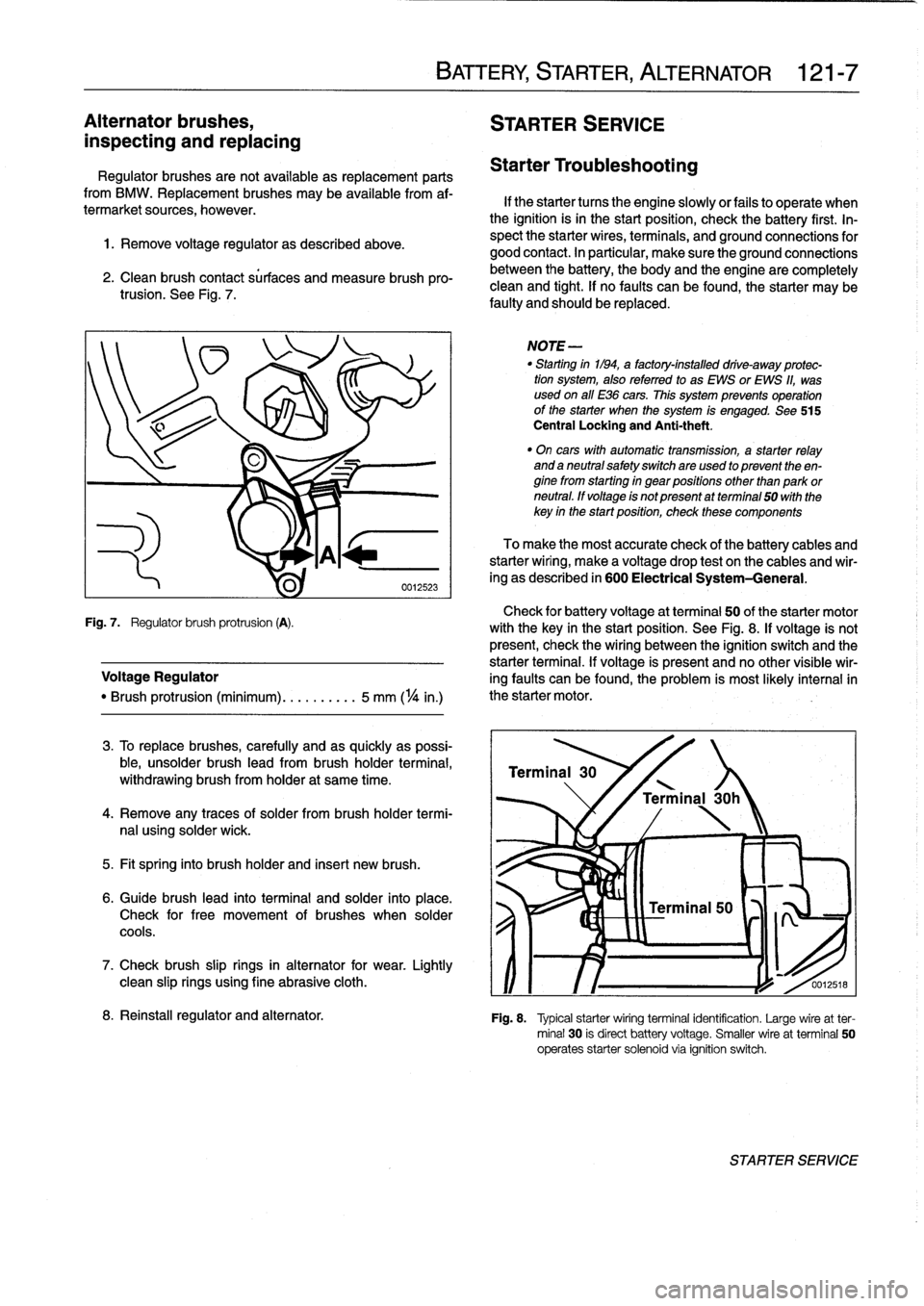
2
.
Clean
brush
contact
sürfaces
and
measure
brush
pro-trusion
.
See
Fig
.
7
.
Check
for
battery
voltage
at
terminal
50
of
the
starter
motor
Fig
.
7
.
Regulator
brush
protrusion
(A)
.
with
the
key
in
the
start
position
.
See
Fig
.
8
.
If
voltage
is
not
present,
check
the
wiring
between
the
ignition
switch
and
the
starter
terminal
.
If
voltage
is
present
and
no
other
visible
wir
Voltage
Regulator
ing
faults
can
be
found,
the
problem
is
most
likely
interna¡in
"
Brush
protrusion
(minimum)
.......
.
..
5
mm
(
1
/4
in
.)
the
starter
motor
.
3
.
To
replace
brushes,
carefully
and
as
quickly
as
possi-
ble,
unsolder
brush
lead
from
brush
holder
termina¡,
withdrawing
brush
from
holder
at
same
time
.
4
.
Remove
any
traces
of
solder
frombrush
holder
termi-
nal
using
solder
wick
.
5
.
Fit
spring
into
brush
holder
and
inserí
new
brush
.
6
.
Guide
brush
lead
into
terminal
and
solder
into
place
.
Check
for
free
movement
of
brushes
when
solder
cools
.
7
.
Check
brush
slip
rings
in
alternator
for
wear
.
Lightly
clean
slip
rings
using
fine
abrasive
cloth
.
BATTERY,
STARTER,
ALTERNATOR
121-
7
Starter
Troubleshooting
If
the
starter
tucos
the
engine
slowlyor
fails
to
operate
when
the
ignition
isin
the
start
position,
check
the
battery
first
.
In-
spect
the
starter
wires,
terminals,
and
ground
connections
for
good
contact
.
In
particular,
make
sure
the
ground
connections
between
the
battery,
the
body
and
the
engine
are
completely
clean
and
tight
.
If
no
faults
can
be
found,
the
starter
may
be
faulty
and
should
be
replaced
.
NOTE
-
"
Starting
in1194,
a
factory-installed
drive-away
protec-
tion
system,
alsoreferred
to
as
EWS
or
EWS
11,
was
used
on
all
E36
cars
.
This
system
prevenís
operation
of
the
starter
when
the
system
is
engaged
.
See
515
Central
Locking
and
Anti-theft
.
"
On
cars
with
automatic
transmission,
a
starter
relay
and
a
neutral
safetyswitchare
used
to
present
theen-
ginefrom
starting
in
gear
positions
other
than
park
or
neutral
.
ff
voltage
is
not
present
atterminal
50
with
the
key
in
the
startposition,
check
these
components
To
make
the
most
accurate
check
of
the
battery
cables
and
starterwiring,
make
a
voltage
drop
test
on
the
cables
and
wir-
ing
as
described
in
600
Electrical
System-General
.
Terminal
30
'
\
/
Terminal
30h
0012518
8
.
Reinstall
regulator
and
alternator
.
Fig
.
8
.
Typical
starterwiring
terminal
identification
.
Large
wireat
ter-
minal
30
is
direct
battery
voltage
.
Smaller
wire
at
terminal
50
operates
starter
solenoid
via
ignition
switch
.
STARTER
SERVICE
Page 144 of 759
121-
8
BATTERY,
STARTER,
ALTERNATOR
1f
the
solenoid
audibly
cliicks
but
the
motor
does
not
turn,
Starter,
removing
and
installing
switch
on
the
lights
andtum
the
key
to
the
start
position
.
lf
the
(6-cylinder
engine
with
lights
go
out
while
attempting
to
start,
the
battery
cable
may
be
manual
transmission)
loose
or
the
starter
may
have
a
short
circuit
.
If
the
lights
stay
on,the
solenoid
is
most
likely
atfault
.
The
starter
on
a
6-cylinder
car
with
manual
transmission
is
Starter,
removing
and
installing
(4-cylinder
engine)
1
.
Disconnect
negative
(-)
battery
cable
.
1
.
Disconnect
negative
(-)
cable
from
battery
.
CAUTION-
Prior
to
disconnecting
the
battery,
read
the
battery
disconnection
cautions
given
at
the
front
of
this
manual
on
page
viii
.
2
.
Remove
guide
tube
for
oil
dipstick
.
3
.
Raise
vehicle
.
WARNING
-
Make
sure
the
car
ís
stable
and
wefl
supported
at
all
times
.
Use
a
professional
automotive
lift
or
jack
stands
designed
forthe
purpose
.
A
floor
jack
is
not
adequate
support
.
4
.
Disconnect
wiring
from
starter
.
5
.
Remove
top
and
bottom
starter
bolts
.
Bottom
bolt
must
be
removed
from
below
car
.
Remove
starter
support
bracket,
if
applicable
.
removed
from
below
.
2
.
Raise
vehicle
.
3
.
Remove
reinforcing
cross
bracefromunder
transmís-
sion,
if
applicable
.
4
.
Remove
cover
from
fuel
filter
and
fuel
lines
on
left
side
underneath
car,
if
applicable
.
Detach
fuel
lines
and
har-
ness
connectors
from
retainingbrackets,
as
necessary
5
.
Disconnect
wiring
from
starter
.
6
.
Loosen
andremove
bolts
and
nuts
fastening
starter
to
transmission
bell
housing
and/or
engine
block
.
Remove
starter
supportbracket
.
7
.
Remove
starter
from
below
.
8
.
Check
starter
pinion
gear
and
flywheel
teeth
for
dam-
age
.
9
.
Installation
is
reverse
of
removal
.
6
.
Pull
starter
downward
and
turn
until
solenoid
is
at
top,
Tightening
Torques
then
remove
from
car
.
"
Re¡
nforcing
cross
brace
to
chassis
(M10)
..
...............
42
Nm
(31
ft-Ib)
7
.
>Check
starter
pinion
gear
and
flywheel
teeth
for
dam-
"
Starter
to
engine
block
(M10
bolt)
...
50
Nm
(37
ft-Ib)
age
.
"
Support
bracket
to
starter
(M5
nut)
...
5
Nm
(44
in-lb)
"
Support
bracket
8
.
Installation
is
reverse
of
removal
.
to
engine
block
(M10
bolt)
.........
47
Nm
(35
ft-Ib)
"
Wire
to
terminal
50
(M6
nut)
.........
6
Nm
(53
ín-Ib)
"
Wire
to
terminal
30
(M8
nut)
.........
12
Nm
(9
ft-lb)
Tightening
Torques
"
Starter
to
engine
block
(M10
bolt)
...
50
Nm
(37
ft-lb)
Wire
to
terminal
50
(M6
nut)
........
6
Nm
(53
in-lb)
"
Wire
toterminal
30
(M8
nut)
...
,
..:.
12
Nm
(9
ft-Ib)
STARTER
SERVICE