Camshaft install BMW 318i 1992 E36 Workshop Manual
[x] Cancel search | Manufacturer: BMW, Model Year: 1992, Model line: 318i, Model: BMW 318i 1992 E36Pages: 759
Page 3 of 759
General
Data
and
010
FundamentalsfortheDo-lt-YourselfOwner
Maintenance
020
Maintenance
Program
Engine
Transmission
Suspension,
Steering
and
Brakes
4
Body
100
Engine-General
110
Engine
Removal
and
Installation
113
Cylinder
Head
Removal
and
Installation
116
Cylinder
Head
and
Valvetrain
117
Camshaft
Timing
Chain
119
Lubrication
System
200
Transmission-General
210
Clutch
230
Manual
Transmission
510
Exterior
Trim,
Bumpers
520
Seats
Bo
y
Equipment
512
DoorWTdws
540
nr
t
513
InteriorTrim
541
Convertible
Top
515
Central
Locking
and
Anti-Theft
600
Electrical
System-General
620
Instruments
Electrical
S
stem
610
Electrical
Component
Locations
630
Exterior
Lighting
611
Wipers
and
Washers
640
Heating
and
Air
Conditioning
6
612
Switches
and
Electrical
Accessories
650
Radio
Equipment
and
720
SeatBelts
Accessories
721
Airbag
System
(SRS)
Electrical
Wiring
Diagrams
Foreword
.
...
.
.
.
..................
.
.
.
.....
.
............
.
...
.
.
.
.
.
................
.
.
.
.....
.
......
.
................
.
.
.
.....
v
Warnings
and
Cautions
.....
.
...
.
.
.
.
.
..........
.
...
.
.
.
.
.
......
.
.........
.
.
.
...
.
.
.
......
.
.
.
.
.
............
.
.
.
.
.
.
.vii
Index
..............
.
.
.
.....
.
............
.
...
.
.
.
.
.
........
.
...
.
.
.
.
.
.......
.
......
.
...
.
.
.
.
.
.
.
........
.
.
.
..
back
of
book
300
Suspension,
Steering
and
330
RearSuspension
Brakes-General
331
Final
Drive
310
Front
Suspension
340
Brakes
320
Steering
and
Wheel
Alignment
400
Body-General
411
Doors
410
Fenders,
Engine
Hood
412
Trunk
Lid
120
Ignition
System
121
Battery,Starter,
Alternator
130
Fue¡
Injection
160
Fuel
Tank
and
Fuel
Pump
170
Radiator
and
Cooling
System180
Exhaust
System
240
Automatic
Transmission
250
Gearshift
Linkage
260
Driveshaft
Page 70 of 759
113-4
CYLINDER
HEAD
REMOVAL
AND
INSTALLATION
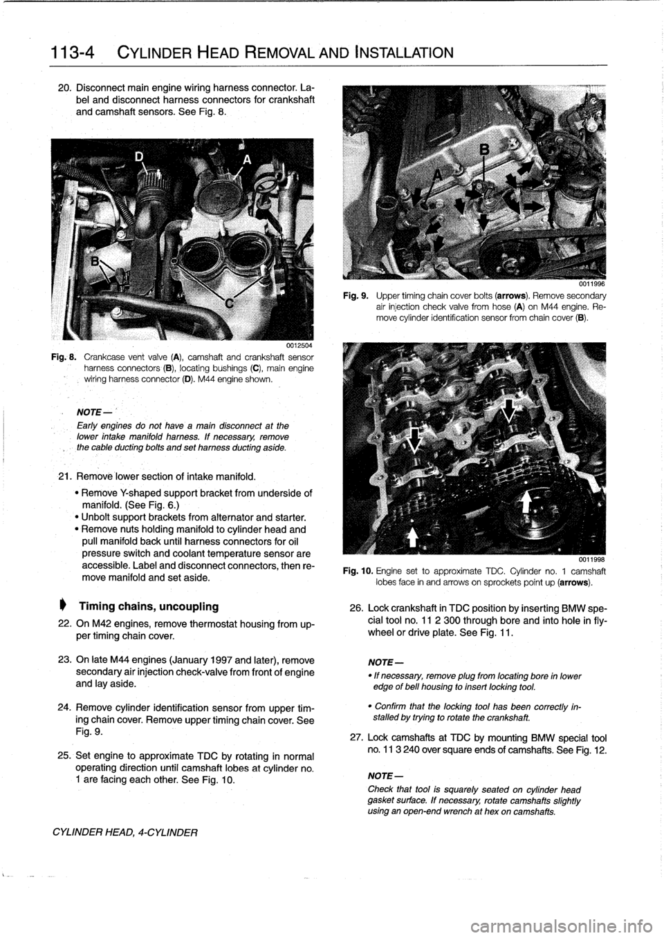
20
.
Disconnect
main
engine
wiring
harness
connector
.
La-
bel
and
disconnect
harness
connectors
for
crankshaft
and
camshaft
sensors
.
See
Fig
.
8
.
0012504
Fig
..
Crankcase
vent
valve
(A),
camshaft
and
crankshaft
sensor
harness
connectors
(B),
locating
bushings
(C),
main
engine
wiring
harnessconnector
(D)
.
M44
engine
shown
.
NOTE-
Early
engines
do
not
havea
maín
disconnect
at
the
lower
intake
manifold
harness
.
lf
necessary,
remove
the
cable
ducting
bolts
and
set
harness
ducting
aside
.
21
.
Remové
lower
section
of
intake
manifold
.
"
Remove
Y
shaped
supportbracket
from
underside
of
manifold
.
(See
Fig
.
6
.)
"
Unbolt
support
brackets
from
alternator
and
starter
.
"
Remove
nuts
holding
manifold
to
cylinder
head
and
pull
manifold
back
until
harness
connectors
for
oil
pressure
switch
and
coolant
temperature
sensorare
accessible
.
Label
and
disconnect
connectors,
then
re-
move
manifold
and
set
aside
.
Timing
chains,
uncoupling
26
.
Lock
crankshaft
in
TDC
position
by
insertíng
BMW
spe-
22
.
On
M42
engines,
remove
thermostat
housing
from
up-
cial
tool
no
.
11
2
300
through
bore
and
into
hole
infly-
per
timing
chaincover
.
wheel
or
driveplate
.
See
Fig
.
11
.
23
.
On
late
M44
engines
(January
1997
and
later),
remove
NOTE-
secondary
air
injection
check-valve
from
front
of
engine
"
If
necessary,
remove
plug
from
locating
bore
in
lower
and
lay
aside
.
edge
of
bell
housing
to
insert
locking
tool
.
24
.
Remove
cylinder
identification
sensor
from
upper
tim-
ing
chaincover
.
Remove
upper
timing
chaincover
.
See
Fig
.
9
.
25
.
Set
engine
to
approximate
TDC
by
rotating
in
normal
operating
direction
until
camshaft
lobes
at
cylinder
no
.
1
are
facing
each
other
.
See
Fig
.
10
.
CYLINDER
HEAD,
4-CYLINDER
Fig
.
9
.
Upper
timing
chain
cover
bolts
(arrows)
.
Remove
secondary
air
injection
check
valve
fromhose
(A)
on
M44
engine
.
Re-
move
cylinder
identification
sensor
from
chaincover
(B)
.
0011998
Fig
.
10
.
Engine
set
to
approximate
TDC
.
Cylinder
no
.
1
camshaft
lobes
face
in
and
arrows
on
sprockets
poínt
up
(arrows)
.
"
Confirm
that
the
locking
tool
has
been
correctly
in-
stalled
by
trying
to
rotate
the
crankshaft
.
27
.
Lock
camshafts
at
TDC
by
mounting
BMW
specíal
tool
no
.
113
240
over
square
ends
of
camshafts
.
See
Fig
.
12
.
NOTE-
Check
that
tool
is
squarely
seated
on
cylinder
head
gasket
surface
.
If
necessary,
rotate
camshafts
slightly
using
an
open-end
wrench
at
hex
oncamshafts
.
Page 71 of 759
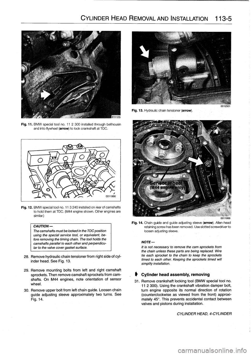
Fig
.
11
.
BMW
special
tool
no
.
11
2300
installed
through
bellhousin
and
finto
flywheel
(arrow)
tolockcrankshaft
at
TDC
.
Fig
.
12
.
BMW
special
tool
no
.
11
3
240
installed
on
rear
of
camshafts
tohold
them
at
TDC
.
(M44
engine
shown
.
Other
engínes
are
similar
.)
CAUTION-
The
camshafts
must
be
locked
in
the
TDC
position
using
the
special
service
tool,
or
equivalent,
be-
fore
removing
the
timing
chaín
.
The
tool
holds
the
camshafts
parallel
to
each
other
and
perpendicu-
larto
the
valve
covergasket
surface
.
CYLINDER
HEAD
REMOVAL
AND
INSTALLATION
113-5
6011966
28
.
Remove
hydraulic
chain
tensiones
from
right
side
ofcyl-
inder
head
.
See
Fig
.
13
.
Fig
.
13
.
Hydraulic
chain
tensioner
(arrow)
.
NOTE-
It
is
not
necessary
to
remove
the
cam
sprockets
from
the
chainuntessthese
parts
are
being
reptaced
.
tire
tie
each
sprocket
to
the
chain
to
keep
the
sprockets
timed
to
each
other
.
Keeping
the
sprockets
timed
will
símplífy
instaftation
.
uu
11999
Fig
.
14
.
Chainguide
and
guide
adjusting
sleeve
(arrow)
.
Allen-head
retaining
screwhasbeen
removed
.
Use
slotted
screwdriver
to
loosen
adjusting
sleeve
.
29
.
Remove
mounting
bolts
from
left
and
right
camshaft
sprockets
.
Then
remove
camshaft
sprockets
from
cam-
_
Cylinder
head
assembly,
removing
shafts
.
On
M44
engines,
note
orientation
of
sensor
31
.
Remove
crankshaft
locking
tool
(BMW
special
tool
no
.
wheel
.
11
2
300)
.
Usingthe
crankshaft
vibration
damper
bolt,
30
.
Remove
upper
bolt
from
left
chainguide
.
Loosen
chain
turn
engine
opposite
its
normal
direction
of
rotation
guide
adjusting
sleeve
approximately
two
turns
.
See
(counterclockwise
asviewed
from
the
front)
approxi
Fig
.
14
.
mately
45°
.
This
prevents
accidental
contact
between
valves
and
pistons
during
installation
.
CYLINDER
HEAD,
4-CYLINDER
Page 72 of 759
113-
6
CYLINDER
HEAD
REMOVAL
AND
INSTALLATION
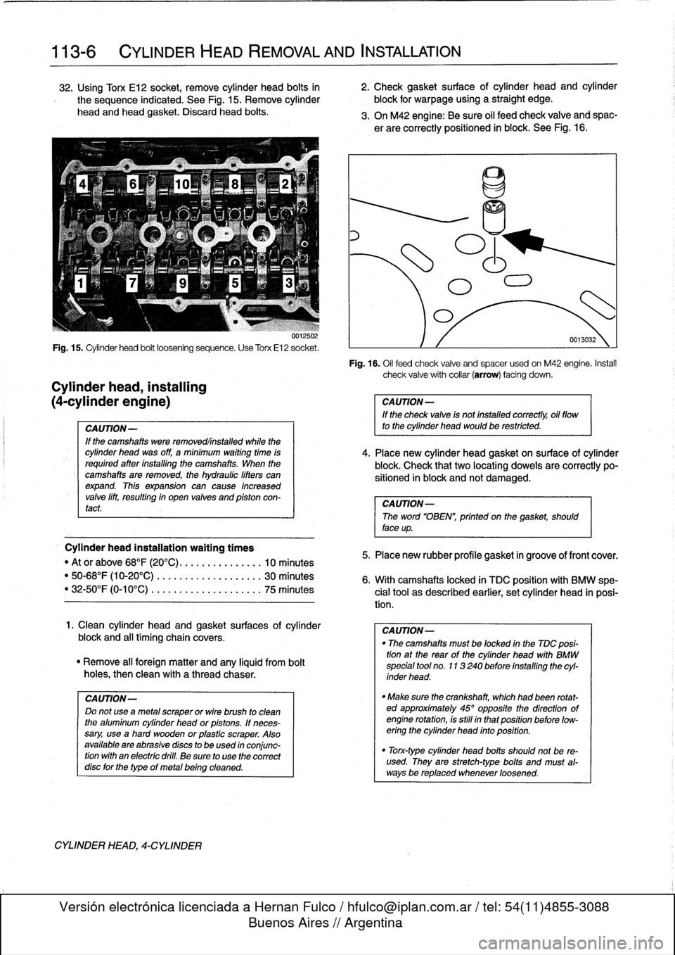
32
.
Using
Torx
E12
socket,
remove
cylinder
head
bolts
in
2
.
Check
gasket
surface
of
cylinder
head
and
cylinder
the
sequence
indicated
.
See
Fig
.
15
.
Remove
cylinder
block
for
warpage
using
a
straight
edge
.
head
and
head
gasket
.
Discard
head
boits
.
3
.
On
M42
engine
:
Be
sure
oil
feed
check
valve
and
spac-
er
are
correctly
positioned
in
block
.
See
Fig
.
16
.
0012502
Fig
.
15
.
Cylinder
head
bolt
loosening
sequence
.
Use
Torx
El
2
socket
.
Cylinder
head,
installing
(4-cylinder
engine)
CAUTION-
If
the
camshafts
were
removedrínstalled
while
the
cylinder
head
was
off,
a
minimum
wafting
time
ís
requíred
after
installing
the
camshafts
.
When
the
camshafts
are
removed,
the
hydraulic
lifters
canexpand
.
This
expansion
can
cause
fncreased
valve
lift,
resultíng
in
open
valves
and
pfston
con-
tact
Cylinder
head
installation
waiting
times
"
Ator
above
68°F
(20°C)
...............
10
minutes
"50-68°F
(10-20°C)
.
.
..
...............
30
minutes
"
32-50°F
(0-10°C)
..
.
..
...............
75
minutes
1
.
Clean
cylinder
head
and
gasket
surfaces
of
cylinder
block
and
al¡
timing
chain
covers
.
"
Remove
al¡
foreign
matter
and
any
¡¡quid
from
bolt
holes,
then
clean
with
a
thread
chaser
.
CAUTION-
Do
not
useametal
scraper
or
wire
brush
to
clean
the
alumfnum
cylinder
head
or
pistons
.
If
neces-
sary,
useahard
wooden
or
plastic
scraper
.
Also
available
are
abrasivediscs
to
be
used
ín
conjunc-
tionwíth
an
electric
dril¡
.
Be
sure
to
use
the
correct
disc
for
the
type
of
metalbeingcleaned
.
CYLINDER
HEAD,
4-CYLINDER
Fig
.
16
.
Oil
feed
check
valve
and
spacer
used
on
M42
engine
.
Install
check
valvewíth
collar
(arrow)
facing
down
.
CAUTION-
If
the
check
valve
is
not
installed
correctly,
oil
flow
to
the
cylinder
head
would
be
restrícted
.
4
.
Place
new
cylinder
head
gasket
on
surface
of
cylinder
block
.
Check
that
two
locating
dowels
are
correctly
po-
sitioned
in
block
and
not
damaged
.
CAUTION-
The
word
"OBEN",
prfnted
on
the
gasket,
should
face
up
.
5
.
Place
new
rubber
profile
gasket
in
groove
of
front
cover
.
6
.
With
camshafts
locked
in
TDC
positionwith
BMW
spe-
cial
tool
as
described
earlier,
set
cylinder
head
in
posi-
tion
.
CAUTION-
"
The
camshafts
mustbe
focked
in
the
TDC
posi-
tion
at
the
rear
of
the
cylinder
head
with
BMW
specfal
tool
no
.
113240
before
installing
the
cyl-
inder
head
.
"
Make
sure
the
crankshaft,
which
had
been
rotat-
ed
approximately
45°
opposite
the
dfrection
of
engine
rotation,
is
still
in
thatposition
before
low-
ering
the
cyffnder
head
ínto
position
.
"
Torx-type
cylinder
head
bolts
should
not
be
re-
used
.
They
are
stretch-type
bolts
and
must
al-
waysbe
replaced
whenever
loosened
.
Page 73 of 759
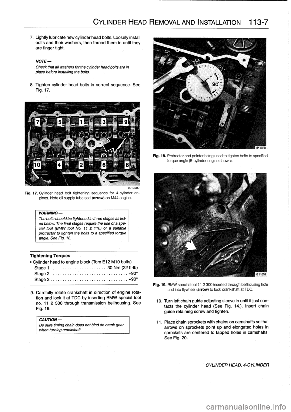
7
.
Lightly
lubricate
new
cylinder
head
bolts
.
Loosely
instan
bolts
and
their
washers,
then
thread
them
in
until
they
are
finger
tight
.
NOTE-
Check
that
all
washers
for
the
cylinder
head
bolts
are
in
place
before
installing
the
bolts
.
8
.
Tighten
cylinder
head
bolts
in
correct
sequence
.
See
Fig
.
17
.
UU125U2
Fig
.
17
.
Cylinder
head
bolt
tightening
sequence
for
4-cylinder
en-
gines
.
Note
oil
supply
tube
seal
(arrow)
on
M44
engine
.
WARNING
-
The
bolts
should
be
tightennd
in
three
stages
as
líst-
ed
below
.
The
final
stages
require
the
use
of
a
spe-
cial
tool
(BMW
tool
No
.
11
2
110)
ora
suitable
protractor
to
tighten
the
bolts
to
a
specified
torqueangle
.
See
Fig
.
18
.
Tightening
Torques
"
Cylinder
head
to
engine
block
(Torx
El2
M10
bolts)
Stage
1
.
.
.....
.
.
.............
30
Nm
(22
ft-Ib)
Stage
2
.
...
...
.
.
...................
..
.
+90°
Stage
3
.....
...
.
..
...................
..
+90°
9
.
Carefully
rotate
crankshaft
in
direction
of
engine
rota-
tion
and
lock
it
at
TDC
by
inserting
BMW
special
tool
no
.
11
2
300
through
transmission
bellhousing
.
See
Fig
.
19
.
CYLINDER
HEAD
REMOVAL
AND
INSTALLATION
113-
7
Fig
.
18
.
Protractor
and
pointer
being
used
to
tighten
bolts
to
specified
torqueangle
(6-cylinder
engine
shown)
.
Fig
.
19
.
BMW
special
tool
11
2
300
inserted
through
bellhousing
hole
and
finto
flywheel
(arrow)
to
lockcrankshaft
at
TDC
.
10
.
Turn
left
chainguide
adjusting
sleeve
in
until
it
just
con-
tacts
the
cylinder
head
(See
Fig
.
14
.)
.
Insert
chain
guide
retaining
screw
and
tighten
.
CAUTION-
11
.
Placechain
sprockets
with
chains
oncamshaftsso
that
Be
sure
timing
chain
does
not
bind
oncrank
gear
when
turning
crankshaft
.
arrowson
sprockets
point
up
and
elongated
holes
in
sprocketsare
centered
to
tapped
holes
in
camshafts
.
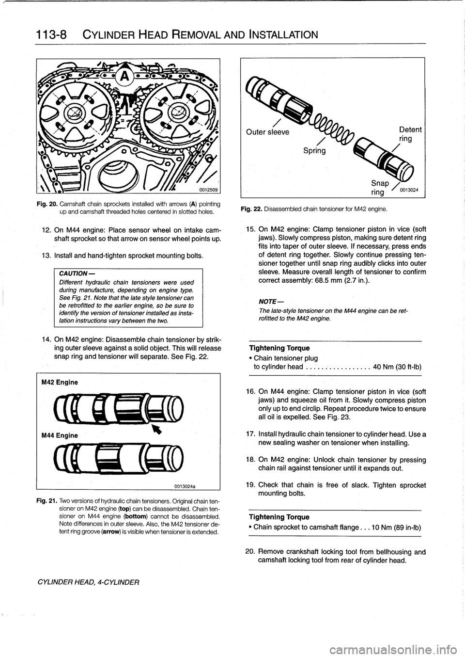
See
Fig
.
20
.
CYLINDER
HEAD,
4-CYLINDER
Page 74 of 759
113-8
CYLINDER
HEAD
REMOVAL
AND
INSTALLATION
IW?
-
L
'/~f
W
~
4r
"
-
"
;,s
1
12
.
On
M44
engine
:
Place
sensor
wheel
on
intake
cam-
shaft
sprocket
so
that
arrowon
sensor
wheel
points
up
.
13
.
Instan
and
hand-tighten
sprocket
mounting
bolts
.
CAUTION-
Different
hydraulic
chaintensioners
were
used
during
manufacture,
depending
onengine
type
.
See
Fig
.
21
.
Note
that
the
late
style
tensioner
can
be
retrofitted
to
the
earlier
engine,
so
be
sure
to
identify
the
version
of
tensioner
installed
as
insta-lation
instructions
vary
between
the
two
.
14
.
On
M42
engine
:
Disassemble
chain
tensioner
by
strik-
ing
outer
sleeve
against
a
solid
object
.
This
will
release
snap
ring
and
tensioner
will
separate
.
See
Fig
.
22
.
M42
Engine
up
and
camshaft
threaded
holes
centered
in
siotted
holes
.
CYLINDER
HEAD,
4-CYLINDER
0013024a
Outer
sl
eve
Detent
ring
Spri
g
Fig
.
22
.
Disassembled
chain
tensioner
for
M42
engine
.
15
.
On
M42
engine
:
Clamp
tensioner
piston
in
vice
(soft
jaws)
.
Slowly
compress
piston,
making
sure
detent
ring
fits
into
taper
of
outer
sleeve
.
If
necessary,
press
ends
of
detent
ring
together
.
Slowly
continuepressing
ten-
sioner
together
until
snap
ring
audibly
clicksinto
outer
sleeve
.
Measure
overall
lengthof
tensioner
to
confirm
correct
assembly
:
68
.5
mm
(2.7
in
.)
.
NOTE-
i
Snap
ring
/0
.13024
The
late-style
tensioner
on
the
M44
engíne
canbe
ret-
rofitted
to
the
M42
engine
.
Tightening
Torque
"Chain
tensioner
plug
to
cylinder
head
.....
.-~
..........
40
Nm
(30
ft-Ib)
16
.
On
M44
engíne
:
Clamp
tensioner
píston
in
vice
(soft
jaws)
and
squeeze
oil
from
it
.
Slowly
compress
piston
only
up
to
end
circlip
.
Repeat
procedure
twice
to
ensure
all
oil
is
expelled
.
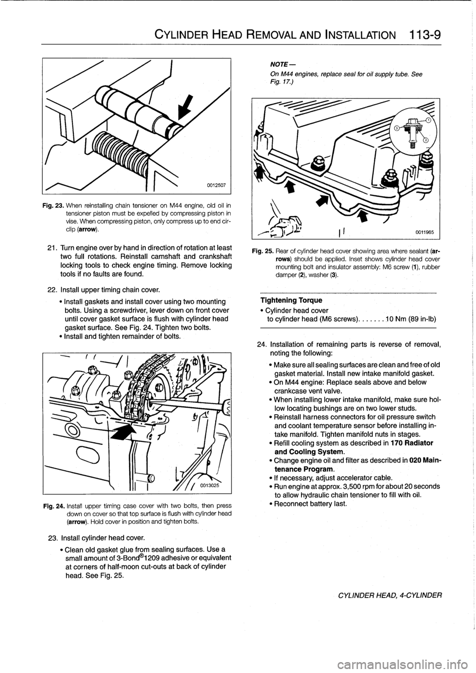
See
Fig
.
23
.
17
.
Instan
hydraulic
chain
tensioner
to
cylinder
head
.
Use
a
new
sealing
washer
on
tensioner
when
installing
.
18
.
On
M42
engine
:
Unlock
chain
tensioner
by
pressing
chain
rail
against
tensioner
until
it
expands
out
.
19
.
Check
that
chain
is
free
of
slack
.
Tighten
sprocket
mounting
bolts
.
Fig
.
21
.
Two
versions
of
hydraulic
chain
tensioners
.
Original
chainten-
sioner
on
M42
engine
(top)
can
be
disassembled
.
Chain
ten
sioner
on
M44
engine
(bottom)
cannotbe
disassembled
.
Tightening
Torque
Note
differences
in
outer
sleeve
.
Also,
the
M42
tensioner
de-
"
Chain
sprocket
to
camshaft
flange
.
..
10
Nm
(89
in-lb)
tent
ring
groove
(arrow)
is
visible
when
tensioner
is
extended
.
20
.
Remove
crankshaft
locking
tool
from
bellhousing
and
camshaft
locking
tool
from
rear
of
cylinder
head
.
Page 75 of 759
Fig
.
23
.
When
reinstalling
chain
tensioner
on
M44
engine,
old
oil
in
tensioner
piston
mustbe
expelled
bycompressing
piston
in
vise
.
When
compressing
piston,
only
compress
up
to
end
cir-
clip
(arrow)
.
21
.
Turn
engine
overby
hand
in
direction
of
rotation
at
least
two
fui¡
rotations
.
Reinstall
camshaft
and
crankshaft
locking
tools
to
check
engíne
timing
.
Remove
locking
tools
if
no
faults
are
found
.
22
.
Insta¡¡
upper
timingchain
cover
.
"
Install
gaskets
and
instan
cover
using
two
mounting
Tightening
Torque
bolts
.
Using
a
screwdriver,
lever
down
on
front
cover
"
Cylinder
head
cover
until
cover
gasket
surface
is
flush
with
cylinder
head
to
cylinder
head
(M6
screws)
.......
10
Nm
(89
in-lb)
gasket
surface
.
See
Fig
.
24
.
Tighten
two
bolis
.
"
Insta¡¡
and
tighten
remainder
of
bolis
.
23
.
Install
cylinder
head
cover
.
CYLINDER
HEAD
REMOVAL
AND
INSTALLATION
113-
9
0012507
Fig
.
24
.
Install
upper
timing
case
cover
with
two
bolis,
then
press
down
on
cover
so
that
top
surface
is
flush
withcylinder
head
(arrow)
.
Hold
cover
in
position
and
tighten
bolis
.
"
Clean
old
gasket
glue
from
sealing
surfaces
.
Usea
small
amount
of
3-Bond
®
1209
adhesive
or
equivalent
at
corners
of
half-moon
cut-outs
at
back
of
cylinder
head
.
See
Fig
.
25
.
NOTE-
OnM44
engines,
reptace
sea¡
for
oil
supply
tube
.
See
Fig
.
17
.)
Fig
.
25
.
Rear
of
cylinder
head
cover
showing
area
where
sealant
(ar-
rows)
should
be
applied
.
Inset
shows
cylinder
head
cover
mounting
bolt
and
insulator
assembly
:
M6
screw
(1),
rubber
damper
(2),
washer
(3)
.
24
.
Installation
of
remaining
parts
is
reverseofremoval,
noting
the
following
:
"
Make
sure
al¡
sealing
surfaces
are
clean
and
free
of
old
gasket
material
.
Install
new
intake
manifold
gasket
.
"
On
M44
engine
:
Replace
seals
above
and
below
crankcase
ventvalve
.
"
When
installing
lower
intake
manifold,
make
sure
hol-
low
locating
bushings
are
on
two
lower
studs
.
"
Reinstall
harness
connectors
for
oil
pressure
switch
and
coolant
temperature
sensor
before
installing
in-
take
manifold
.
Tighten
manifold
nuts
in
stages
.
"
Refill
cooling
system
as
described
in
170
Radiator
and
Cooling
System
.
"
Change
engine
oil
and
filter
as
described
in
020
Main-
tenance
Program
.
"
If
necessary,
adjust
accelerator
cable
.
"
Run
engine
at
approx
.
3,500
rpm
for
about
20
seconds
to
allow
hydraulic
chain
tensioner
to
fill
with
oil
.
"
Reconnect
battery
last
.
CYLINDER
HEAD,-CYLINDER
Page 77 of 759
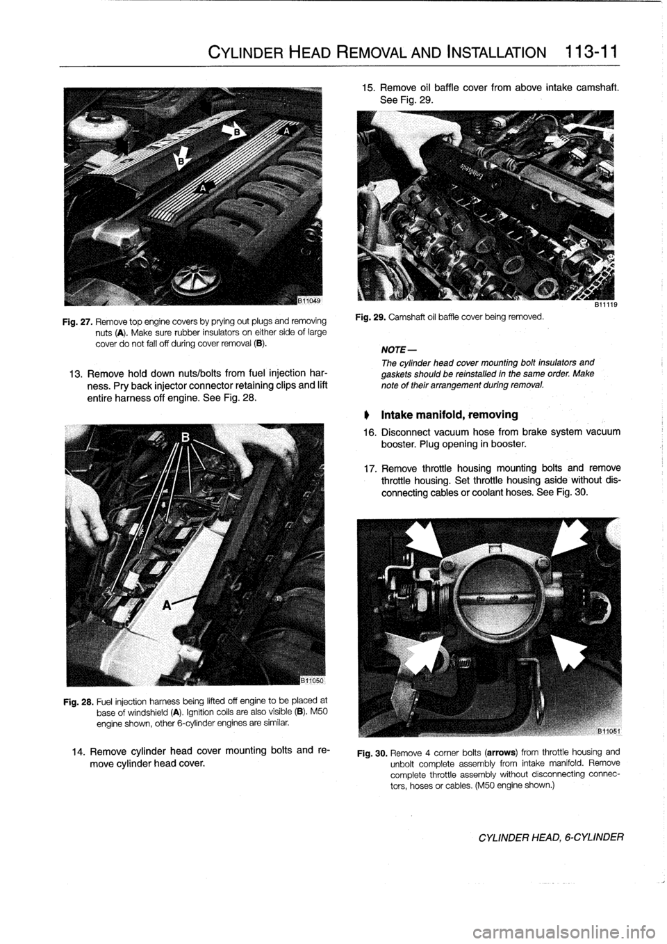
Fig
.
27
.
Remove
top
enginecovers
by
prying
out
plugs
and
removing
nuts
(A)
.
Make
sure
rubber
insulators
on
either
side
of
large
cover
do
not
fall
off
during
cover
removal
(B)
.
Fig
.
28
.
Fuel
injection
harness
beíng
lifted
off
engine
to
be
placed
at
base
of
windshield
(A)
.
Ignitioncoils
are
also
visible
(B)
.
M50
engine
shown,
other
6-cylinder
engines
are
similar
.
14
.
Remove
cylinder
head
cover
mounting
bolts
and
re-
move
cylinder
head
cover
.
CYLINDER
HEAD
REMOVAL
AND
INSTALLATION
113-
11
15
.
Remove
oil
baffle
cover
from
above
intake
camshaft
.
See
Fig
.
29
.
Fig
.
29
.
Camshaft
oil
baffle
coverbeing
removed
.
NOTE-
The
cylinder
head
cover
mounting
bolt
insulators
and
13
.
Remove
hold
down
nuts/bolts
from
fuel
injection
har-
gaskets
should
be
reinstalled
in
the
same
order
.
Make
ness
.
Pry
back
injector
connector
retaining
clips
and
lift
note
of
their
arrangement
during
removal
.
entire
harness
off
engine
.
See
Fig
.
28
.
Intake
manifold,
removing
811119
16
.
Disconnect
vacuum
hose
from
brake
system
vacuum
booster
.
Plug
opening
in
booster
.
17
.
Remove
throttle
housing
mounting
bolts
and
remove
throttle
housing
.
Set
throttle
housing
aside
without
dis-
connecting
cablesor
coolant
hoses
.
See
Fig
.
30
.
Fig
.
30
.
Remove
4
comer
bolts
(arrows)
from
throttle
housing
and
unbolt
complete
assembly
from
intake
manifold
.
Remove
complete
throttle
assembly
without
disconnecting
connec-
tors,
hoses
or
cables
.
(M50
engine
shown
.)
CYLINDER
HEAD,
6-CYLINDER
Page 78 of 759
113-12
CYLINDER
HEAD
REMOVAL
AND
INSTALLATION
18
.
Working
from
underside
of
intake
manifold,
disconnect
21
.
Detach
oil
dipstick
guide
tube
from
manifold
.
Disconharness
connectors,
vent
hoses,
and
air
bypass
nectvent
hose
at
base
of
dipstick
.
hoses)
.
22
.
Remove
intake
manifold
from
engine
byremoving
sev-19
.
Working
at
rear
of
intake
manifold,
label
and
disconnect
en
mounting
nuts
from
above
andtwo
support
bracket
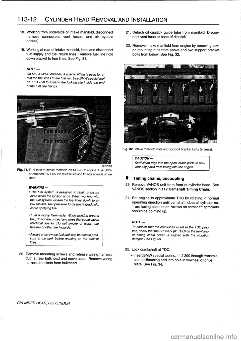
fuel
supply
and
fuel
return
lines
.
Remove
fuelline
hold
bolts
from
below
.
See
Fig
.
32
.
down
bracket
to
free
lines
.
See
Fig
.
31
.
NOTE-
On
M52IS52US
engines,
a
special
fitting
is
used
to
re-tain
the
fuel
fines
to
the
fuel
rail
.
Use
BMW
special
tool
no
.
16
1
050
to
expand
the
locking
clip
inside
the
end
of
the
fuellíne
fittings
.
WARNING
-
"
The
fuel
system
is
desígned
to
retan
pressure
even
wheh
the
ignition
is
off
.
When
working
with
the
fuel
system,
loosen
the
fuel
lines
slowly
toal-
low
residual
fuel
pressure
to
dissipate
gradually
.
Avoid
spraying
fuel
.
"
Fuel
is
highly
flammable
.
When
working
around
fuel,
do
not
disconnect
any
wires
that
could
cause
electrfcal
sparks
.
Do
not
smoke
orwork
near
heaters
or
other
fire
hazards
.
"
Always
unscrew
the
fuel
tank
cap
to
release
pres-
sure
in
the
tank
before
working
on
the
tank
or
lines
.
20
.
Remove
mountingscrews
and
release
wiring
harness
duct
at
rear
bulkhead
and
move
aside
.
Remove
wiring
harness
brackets
frombulkhead
.
CYLINDER
HEAD,
6-CYLINDER
Fig
.
32
.
Intake
manifoldnuts
and
support
bracket
bolts
(arrows)
.
CAUTION-
Stuff
clean
rags
into
the
open
intake
ports
topre-
001269s
vent
any
ports
from
falfing
into
the
engine
.
Fig
.
31
.
Fuel
lines
at
intake
manifold
on
M52/S52
engine
.
Use
BMW
special
tool
16
1
050
to
release
locking
fittings
at
ends
of
fuel
enes
.
1
Timing
chains,
uncoupling
23
.
Remove
VANOS
unit
from
frontof
cylinder
head
.
See
VANOS
section
in
117
Camshaft
Timing
Chain
.
24
.
Setengine
to
approximate
TDC
by
rotating
in
normal
operating
direction
until
camshaft
lobes
at
cylinder
no
.
1
are
facing
each
other
.
Arrows
on
camshaft
sprockets
should
be
pointing
up
.
NOTE-
To
confirm
that
the
crankshaft
is
set
to
the
TDC
posi-
tion,
check
that
the
OIT
mark
(0°
TDC)on
the
front
low-
er
timing
chain
cover
ís
aligned
with
the
víbration
damperSee
Fig
.
33
.
25
.
Lock
crankshaft
at
TDC
.
"
Insert
BMW
special
tool
no
.
11
2
300
through
transmis-
sion
bellhousing
and
finto
hole
in
flywheelor
drive
plate
.
See
Fig
.
34
.
Page 79 of 759
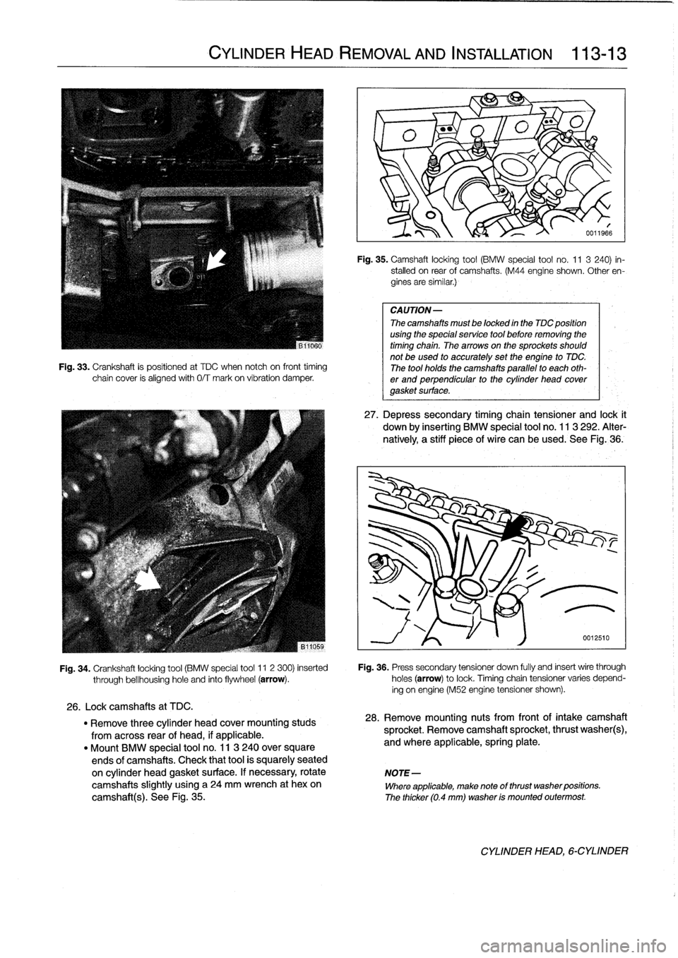
Fig
.
33
.
Crankshaft
is
positioned
at
TDC
when
notch
oh
front
timing
chain
cover
is
alignedwith
0/T
mark
on
víbration
damper
.
CYLINDER
HEAD
REMOVAL
AND
INSTALLATION
113-
1
3
Fig
.
35
.
Camshaft
locking
tool
(BMW
special
tool
no
.
11
3
240)
in-
stalled
on
rear
of
camshafts
.
(M44
engine
shown
.
Other
en-
gines
are
similar
.)
CAUTION-
The
camshafts
must
be
locked
in
the
TDC
position
using
the
special
service
tool
before
removing
the
timing
chain
.
Thearrowson
the
sprockets
should
not
be
used
to
accurately
set
the
engine
to
TDC
.
The
tool
holds
the
camshafts
parallel
to
each
oth-
er
and
perpendicular
to
the
cylinder
head
covergasket
surface
.
27
.
Depress
secondary
timing
chain
tensioner
and
lock
t
down
by
inserting
BMW
special
tool
no
.
113
292
.
Alter-
natively,
a
stiff
piece
of
wire
can
be
used
.
See
Fig
.,36
.
Fig
.
34
.
Crankshaft
locking
tool
(BMW
special
tool
11
2
300)
inserted
Fig
.
36
.
Press
secondary
tensioner
down
fully
and
insert
wire
through
through
bellhousinghole
and
finto
flywheel
(arrow)
.
holes
(arrow)
to
lock
.
Timingchain
tensioner
varies
depend-
ing
on
engine
(M52
engine
tensioner
shown)
.
26
.
Lockcamshafts
at
TDC
.
"
Remove
three
cylinder
head
cover
mounting
studs
28
.
Remove
mounting
nuts
from
front
of
intake
camshaft
from
across
rear
of
head,
if
applicable
.
sprocket
.
Remove
camshaft
sprocket,
thrust
washer(s),
"
Mount
BMW
special
tool
no
.
11
3
240
over
square
and
where
applicable,
spring
plate
.
ends
of
camshafts
.
Check
that
tool
is
squarely
seated
on
cylinder
head
gasket
surface
.
If
necessary,
rotate
NOTE-
camshafts
slightly
using
a
24
mm
wrench
at
hexon
Where
applicable,
make
note
of
thrust
washer
positions
.
camshaft(s)
.
See
Fig
.
35
.
The
thicker
(0
.4
mm)
washer
is
mounted
outermost
.
CYLINDER
HEAD,6-CYLINDER