Ignition wiring BMW 318i 1992 E36 Workshop Manual
[x] Cancel search | Manufacturer: BMW, Model Year: 1992, Model line: 318i, Model: BMW 318i 1992 E36Pages: 759
Page 3 of 759
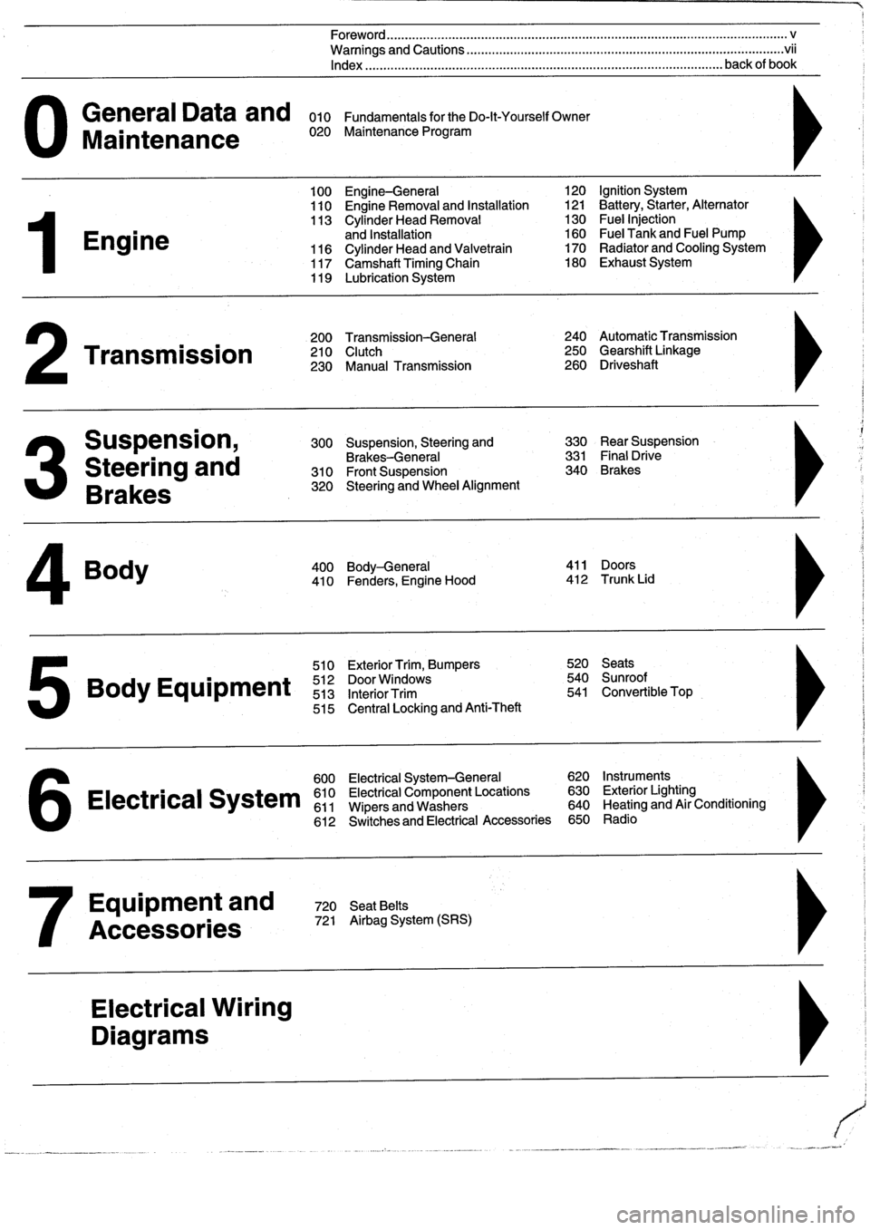
General
Data
and
010
FundamentalsfortheDo-lt-YourselfOwner
Maintenance
020
Maintenance
Program
Engine
Transmission
Suspension,
Steering
and
Brakes
4
Body
100
Engine-General
110
Engine
Removal
and
Installation
113
Cylinder
Head
Removal
and
Installation
116
Cylinder
Head
and
Valvetrain
117
Camshaft
Timing
Chain
119
Lubrication
System
200
Transmission-General
210
Clutch
230
Manual
Transmission
510
Exterior
Trim,
Bumpers
520
Seats
Bo
y
Equipment
512
DoorWTdws
540
nr
t
513
InteriorTrim
541
Convertible
Top
515
Central
Locking
and
Anti-Theft
600
Electrical
System-General
620
Instruments
Electrical
S
stem
610
Electrical
Component
Locations
630
Exterior
Lighting
611
Wipers
and
Washers
640
Heating
and
Air
Conditioning
6
612
Switches
and
Electrical
Accessories
650
Radio
Equipment
and
720
SeatBelts
Accessories
721
Airbag
System
(SRS)
Electrical
Wiring
Diagrams
Foreword
.
...
.
.
.
..................
.
.
.
.....
.
............
.
...
.
.
.
.
.
................
.
.
.
.....
.
......
.
................
.
.
.
.....
v
Warnings
and
Cautions
.....
.
...
.
.
.
.
.
..........
.
...
.
.
.
.
.
......
.
.........
.
.
.
...
.
.
.
......
.
.
.
.
.
............
.
.
.
.
.
.
.vii
Index
..............
.
.
.
.....
.
............
.
...
.
.
.
.
.
........
.
...
.
.
.
.
.
.......
.
......
.
...
.
.
.
.
.
.
.
........
.
.
.
..
back
of
book
300
Suspension,
Steering
and
330
RearSuspension
Brakes-General
331
Final
Drive
310
Front
Suspension
340
Brakes
320
Steering
and
Wheel
Alignment
400
Body-General
411
Doors
410
Fenders,
Engine
Hood
412
Trunk
Lid
120
Ignition
System
121
Battery,Starter,
Alternator
130
Fue¡
Injection
160
Fuel
Tank
and
Fuel
Pump
170
Radiator
and
Cooling
System180
Exhaust
System
240
Automatic
Transmission
250
Gearshift
Linkage
260
Driveshaft
Page 43 of 759
GENERAL
.
.....
.
.
.
.
.
.
.
...
.
.
.
.
.
.
.
.
.
...
100-1
Cylinder
Block
and
Crankshaft
.
.
.
.
.
.
.
.
.
...
100-1
Connecting
Rods
and
Pistons
.
.
.
.
.
.
.
.
.
.
.
.
.
100-1
Cylinder
Head
and
Valvetrain
.
.
.
.
.
.
.
.
.
.
.
.
.
100-2
VANOS
(Variable
Valve
Timing)
.
.
.
.
.
.
.
.
...
100-2
DISA
(Dual
Resonance
Intake
System)
.
.
.
.
.
100-3
Engine
Management
System
.
.
.
.
.
.
.
.
.
.
.
.
.
100-3
Ignition
......
.
.
.
.........
.
.
.
.
.
.
.
.
.
.
.
.
100-5
Fuel
Delivery
..
.
.
.
.....
.
...
.
.
.
.
.
.
.
.
.
.
.
.
100-5
Cooling
System
.
...........
.
.
.
.
.
.....
.
.
100-5
Lubrication
System
.........
.
.
.
.
.
.
.
.
.
.
.
.
100-5
MECHANICALTROUBLESHOOTING
.
.
.
.
100-5
Warnings
and
Cautions
..
.
...
.
.
.
.
.
.
.
.
.
.
.
.
100-5
Cylinder
compression,
checking
.
.
.
.
.
.
.
.
.
.
.
100-6
EngineMechanical
Troubleshooting
Table
.
.
.
100-7
DRIVEABILITY
TROUBLESHOOTING
...
100-8
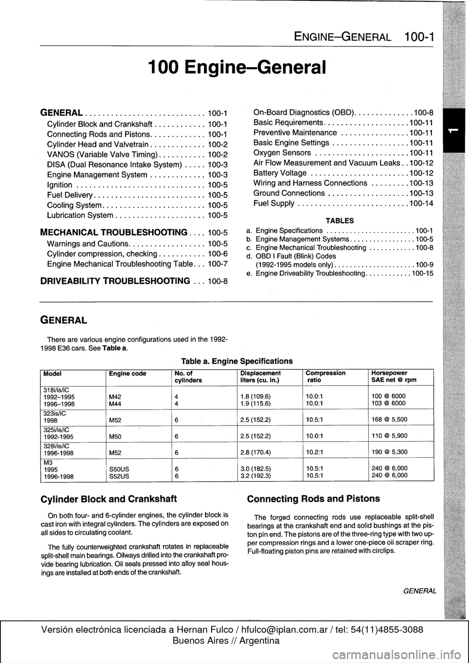
GENERAL
There
are
various
engíne
configurations
used
in
the
1992-
1998
E36
cars
.
See
Table
a
.
On
both
four-
and
6-cylinder
engines,
the
cylinder
block
is
cast
¡ron
with
integral
cyiinders
.
The
cyiinders
are
exposed
on
all
sides
to
circulating
coolant
.
The
fully
counterweighted
crankshaft
rotates
in
replaceable
split-shell
main
bearings
.
Oiiways
drilled
into
the
crankshaft
pro-
vide
bearing
lubrication
.
O¡I
seals
pressed
into
alloy
sea¡
hous-
ings
are
installedat
both
ends
of
the
crankshaft
.
100
Engine-General
Tablea
.
Engine
Specifications
ENGINE-GENERAL
100-1
On-Board
Diagnostics
(OBD)
...
.
.
.
.
.
.
.
.
.
.
.
100-8
Basic
Requirements
....
.
.
.
...
.
.
.
.
.
....
.100-11
Preventive
Maintenance
......
.
.
.
.
.
.....
100-11
Basic
Engine
Settings
..
.
.....
.
.
.
.
.
.....
100-11
Oxygen
Sensors
.
.
.
...
.
.
.
...
.
.
.
.
.
....
.100-11
Air
Flow
Measurement
and
Vacuum
Leaks
.
.100-12
Battery
Voltage
.
.
...........
.
.
.
.
.
.....
100-12
Wiring
and
Harness
Connections
.
.
.
.
.....
100-13
Ground
Connections
...
.
.....
.
.
.
.
.
.....
100-13
Fue¡
Supply
....
.
...........
.
.
..
.....
.100-14
TABLES
a
.
Engine
Specifications
...
...
...........
.
..
..
.100-1
b
.
Engine
Management
Systems
..
..
...........
..
100-5
c
.
Engine
Mechanical
Troubleshooting
..........
.
.
100-8
d
.
OBD
1
Fault
(Blink)
Codes
(1992-1995
models
only)
.
...
..
..
..........
..
.100-9
e
.
Engine
Driveability
Troubleshooting
...........
.100-15
Model
Engine
code
No
.
of
Dispiacement
Compression
Horsepower
cyiinders
liters
(cu
.
in
.)
ratio
SAE
net
@
rpm
318i/is/¡C
1992-1995
M42
4
1
.8
(109
.6)
10
.0
:1
100
@
6000
1996-1998
M44
4
1
.9
(115
.6)
~
10
.0
:1
103
@
6000
323ís/iC
1998
M52
6
2
.5
(152
.2)
10
.5
:1
168
@
5,500
325i/is/iC
1992-1995
M50
6
2
.5
(152
.2)
10
.0
:1
110
@
5,900
328i/is/iC
1996-1998
M52
6
2
.8
(170
.4)
10
.2
:1
190
@
5,300
M3
1995
S50US
6
3
.0
(182
.5)
10
.5:1
240
@
6,000
1996-1998
S52US
6
3
.2
(192
.3)
10
.5:1
240
@
6,000
Cylinder
Block
and
Crankshaft
Connecting
Rods
and
Pistons
The
forged
connecting
rods
use
replaceable
split-shell
bearings
at
the
crankshaft
endand
solid
bushings
at
the
pis-
ton
pin
end
.
The
pistonsare
of
the
three-ring
typewith
two
up-
per
compression
rings
and
a
lowerone-piece
o¡i
scraper
ring
.
Fui¡-floating
piston
pins
are
retained
with
circlips
.
GENERAL
Page 47 of 759
ignition
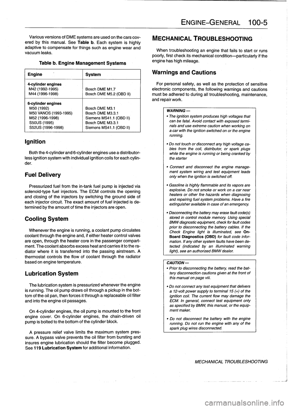
Table
b
.
Engine
Management
Systems
engine
has
high
mileage
.
Engine
1
System
4-cylinder
engines
M42
(1992-1995)
Bosch
DME
Ml
.7
M44
(1996-1998)
Bosch
DME
M5
.2
(OBD
II)
6-cylinder
engines
M50
(1992)
Bosch
DME
M3
.1
M50
VANOS
(1993-1995)
Bosch
DME
M3
.3
.1
M52
(1996-1998)
Siemens
MS41
.1
(OBD
II)
S50US
(1995)
Bosch
DME
M3
.3
.1
S52US
(1996-1998)
Siemens
MS41
.1
(OBD
II)
Both
the
4-cylinder
and
6-cylinder
engines
use
a
distributor-
less
ignition
system
with
individual
ignition
coils
for
each
cylin-
der
.
FuelDelivery
Pressurized
fuel
from
the
in-tank
fuel
pump
is
injected
via
solenoid-type
fuel
injectors
.
The
ECM
controls
the
opening
and
closing
of
the
injectors
by
switchingthe
ground
side
of
each
injector
circuit
.
The
exact
amount
of
fuel
injected
is
de-
termined
by
the
amount
of
timethe
injectors
are
open
.
Cooling
System
Whenever
the
engine
is
running,
acoolant
pump
circulates
coolant
through
the
engine
and,
if
either
heater
control
valves
are
open,
through
the
heater
core
in
the
passenger
compart-
ment
.
The
coolant
absorbs
excess
heat
and
carries
it
to
the
ra-
diator
where
it
is
transferred
into
the
passing
airstream
.
A
thermostat
controls
the
flow
of
coolant
through
the
radiator
based
on
engine
temperature
.
Lubrication
System
The
lubrication
system
is
pressurized
whenever
theengine
is
running
.
The
oil
pump
draws
oil
through
a
pickup
in
the
bot-
tom
of
the
oil
pan,thenforces
it
through
a
replaceable
oil
filter
and
finto
the
engine
oíi
passages
.
On
4-cylinder
engines,
the
oil
pump
is
mounted
to
the
front
engine
cover
.
On
6-cylinder
engines,thechain-driven
oil
pump
is
bolted
to
the
bottom
of
the
cylinder
block
.
A
pressure
relief
valve
limits
the
maximum
system
pres-
sure
.
A
bypass
valve
prevents
the
oil
filter
from
bursting
and
insures
engine
lubrication
should
the
filter
become
plugged
.
See
119
Lubrication
System
for
additional
information
.
ENGINE-GENERAL
100-
5
Various
versions
of
DME
systems
are
usedon
thecars
cov-
MECHANICAL
TROUBLESHOOTING
ered
by
this
manual
.
See
Table
b
.
Each
system
is
highly
adaptive
to
compensate
for
things
suchasengine
wear
and
When
troubleshooting
an
engine
that
fails
to
start
or
runs
vacuum
leaks
.
poorly,
first
check
its
mechanical
condition-particularly
if
the
Warnings
and
Cautions
For
personal
safety,
as
well
asthe
protection
of
sensitive
electronic
components,
the
following
warnings
and
cautions
must
be
adhered
to
during
all
troubleshooting,
maintenance,
and
repairwork
.
WARNING
-
"
The
ignition
system
produces
high
voltages
that
can
be
fatal
.
Avoid
contact
with
exposed
termi-
nals
anduse
extreme
caution
when
working
on
a
car
with
the
ignition
switched
on
or
the
engine
running
.
"
Do
not
touch
or
disconnect
any
high
voltage
ca-
bles
from
the
coil,
distributor,
orspark
plugs
while
the
engine
is
running
or
being
cranked
by
the
starter
"
Connect
and
disconnect
the
engine
manage-
ment
system
wiring
and
test
equipment
leads
only
when
the
ignition
is
switched
off
.
"
Gasoline
is
highly
flammable
and
its
vapors
are
explosive
.
Do
not
smoke
or
work
on
a
car
near
heaters
or
other
fire
hazards
when
diagnosing
and
repairing
fuel
system
problems
.
Have
a
fire
extínguisher
available
in
case
of
an
emergency
.
"
Disconnecting
the
battery
may
erase
fault
code(s)
stored
in
control
module
memory
.
Using
special
BMW
diagnosnnc
equipment,
check
for
fault
codes
prior
to
disconnecting
the
battery
cables
.
If
the
Check
Engine
lightis
illuminated,
see
On-
Board
Diagnostics
(OBD)
forfault
code
infor-
mation
.
If
any
other
system
faults
havebeen
de-tected
(indicated
byan
illuminated
warning
light),
see
an
authorized
BMW
dealer
.
CAUTION-
"
Prior
to
disconnecting
the
battery,
read
the
bat-
tery
disconnection
cautions
gíven
at
the
front
of
this
manual
on
page
viii
.
"
Do
notconnect
any
test
equipment
that
delivers
a
12-volt
power
supply
to
terminal15
(+)
of
the
ignition
coil
.
The
current
flow
may
damage
the
ECM
.
In
general,
connect
test
equipment
only
as
specified
by
BMW,
this
manual,
or
the
equip-
ment
maker
.
"
Do
not
disconnect
the
battery
with
the
engine
running
.
Do
notrunthe
engine
with
any
of
the
sparkplug
wires
disconnected
.
MECHANICAL
TROUBLESHOOTING
Page 51 of 759
NOTE-
"
On
carswith
OBD
ti,
specialized
OBD
11
scan
tool
equipment
must
be
used
to
access
the
DTCs,
either
using
the
BMW
special
tool
ora
`generic"
OBD
11
scan
tool
.
See
130
Fuel
Injection
.
"
The
08D
11
fault
memory
(including
an
iiluminated
Check
Engine
light)
can
only
be
reset
using
the
spe-
cial
scan
tool
.
Removing
the
connector
from
the
ECM
or
disconnecting
the
battery
will
not
erase
the
fault
memory
.
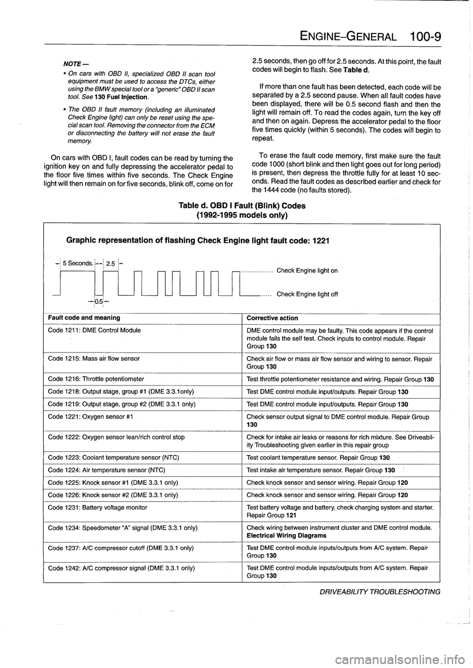
Table
d
.
OBD
1
Fault
(Blink)
Codes
(1992-1995
modeis
only)
Graphic
representation
of
flashing
Check
Engine
light
fault
code
:
1221
5
Seconds
.
:-
2
.5~-
--05--
Fault
code
and
meaning
1
Corrective
action
Code
1216
:
Throttle
potentiometer
Code
1218
:
Output
stage,
group#1
(DME
3
.3
.ionly)
Code
1219
:
Output
stage,
group
#2
(DME
3
.3.1
only)
Code
1221
:
Oxygen
sensor
#1
Code
1224
:
Air
temperature
sensor
(NTC)
Code
1226
:
Knock
sensor
#2
(DME
3
.3
.1
only)
130
ENGINE-GENERAL
100-
9
2
.5
seconds,
then
go
off
for
2
.5
seconds
.
At
thispoint,
the
fault
codes
will
begin
to
flash
.
See
Table
d
.
If
more
than
one
fault
has
been
detected,
eachcode
will
be
separated
by
a2
.5
second
pause
.
When
al¡
fault
codes
havebeen
displayed,
there
will
be0
.5
second
flash
and
thenthe
light
will
remain
off
.
To
read
the
codes
again,
turn
the
key
off
and
then
on
again
.
Depress
theaccelerator
pedal
to
the
floor
five
times
quickly
(within
5
seconds)
.
The
codes
will
begin
to
repeat
.
On
cars
with
OBD
I,
fault
codes
can
be
read
by
turning
the
To
erase
the
fault
code
memory,
first
make
sure
the
fault
ignition
key
on
and
fully
depressing
theaccelerator
pedal
to
code
1000
(short
blink
and
then
light
goes
out
for
long
period)
the
floor
five
times
within
five
seconds
.
TheCheck
Engine
is
present,
then
depress
the
throttle
fully
for
at
least
10
sec-
light
will
then
remain
on
for
five
seconds,
blink
off,
come
on
for
onds
.
Read
the
fault
codes
as
described
earlier
and
check
for
the
1444
code
(no
faults
stored)
.
-,--------------
Check
Engine
light
on
Check
Engine
light
off
Code
1211
:
DM
E
Control
Module
DME
control
module
may
be
faulty
.
This
code
appears
if
the
control
module
fails
the
self
test
.
Check
inputsto
control
module
.
Repair
Group
130
Code
1215
:
Mass
air
flow
sensor
Check
air
flow
or
mass
air
flow
sensor
and
wiring
to
sensor
.
Repair
Group
130
Test
throttle
potentiometer
resistance
and
wiring
.
Repair
Group
130
Test
DME
control
module
input/outputs
.
Repair
Group
130
Test
DME
control
module
input/outputs
.
Repair
Group
130
Check
sensor
output
signal
to
DME
control
module
.
Repair
Group
Code
1222
:
Oxygen
sensor
lean/rich
control
stop
Check
for
intake
air
leaks
or
reasons
forrich
míxture
.
See
Driveabil-
ity
Troubleshooting
given
earlier
in
this
repair
group
Code
1223
:
Coolant
temperaturesensor
(NTC)
1
Test
coolant
temperature
sensor
.
Repair
Group
130
Test
intake
air
temperature
sensor
.
Repair
Group
130
Code
1225
:
Knock
sensor#1
(DME
3
.3
.1
only)
1
Check
knocksensorand
sensor
wiring
.
Repair
Group
120
Check
knocksensor
and
sensor
wiring
.
Repair
Group
120
Code
1231
:
Batteryvoltage
monitor
Test
battery
voltage
and
battery
check
charging
system
and
starter
.
Repair
Group
121
Code
1234
:
Speedometer
"A"signal
(DME
3
.3
.1
only)
Check
wiring
between
instrument
cluster
and
DME
control
module
.
Electrical
Wiring
Diagrams
Code
1237
:
A/C
compressor
cutoff
(DME
3
.3
.1
only)
Test
DME
control
module
inputs/outputs
from
A/C
system
.
Repair
Group
130
Code
1242
:
A/C
compressor
signal
(DME
3
.3.1
only)
Test
DME
control
module
inputs/outputs
from
A/C
system
.
Repair
Group
130
DRIVEABILITY
TROLIBLESHOOTING
Page 52 of 759
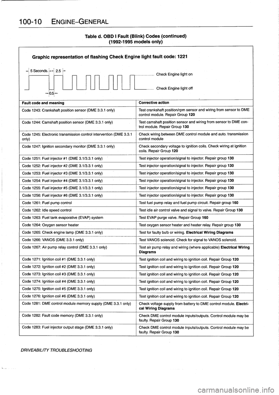
100-
1
0
ENGINE-GENERAL
Table
d
.
OBD
I
Fault
(Blink)
Codes
(continued)
(1992-1995
modeis
only)
Graphic
representation
of
flashing
Check
Engine
light
fault
code
:
1221
-
;
5
Seconds
.
;--~
2
.5
r
----------------
Check
Engine
light
on
Fault
code
and
meaning
Corrective
action
Check
Engine
light
off
Code
1243
:
Crankshaft
position
sensor
(DME
3
.3
.1
only)
Test
crankshaft
position/rpm
sensor
and
wiring
from
sensor
lo
DME
control
module
.
Repair
Group
120
Code
1244
:
Camshaft
position
sensor
(DME
3
.3
.1
only)
Test
camshaft
position
sensor
and
wiring
fromsensor
to
DME
con-
trol
module
.
Repair
Group
130
Code
1245
:
Electronic
transmission
control
intervention
(DME
3
.3
.1
Check
wiring
between
DME
control
module
and
auto
.
transmission
only)
control
module
Code
1247
:
Ignition
secondary
monitor
(DME
3
.3
.1
only)
Check
secondary
voltage
lo
ignition
coils
.
Check
wiringat
ignition
coils
.
Repair
Group
120
Code
1251
:
Fuel
injector
#1
(DME
3
.113
.3
.1
only)
1
Test
injector
operation/signal
lo
injector
.
Repair
group130
Code
1252
:
Fuel
injector
#2
(DME
3
.113
.3
.1
only)
Test
injector
operation/signal
lo
injector
.
Repair
group130
Code
1253
:
Fuel
injector
#3
(DME
3
.1/3
.3
.1
only)
Test
injector
operation/signal
to
injector
.
Repair
group130
Code
1254
:
Fuel
injector
#4
(DME
3
.1/3
.3
.1
only)
Test
injector
operation/signal
to
injector
.
Repair
group
130
Code
1255
:
Fuel
injector
#5
(DME
3
.1/3
.3
.1
only)
Test
injector
operation/signal
to
injector
.
Repair
group130
Code
1256
:
Fuel
injector
#6
(DME
3
.1/3
.3
.1
only)
Test
injector
operation/signal
lo
injector
.
Repair
group130
Code
1261
:
Fuel
pump
control
Test
fuel
pump
relay
and
fuel
pump
circuit
.
Repairgroup
160
Code
1262
:
Idle
speed
control
Test
idleair
controlvalve
and
signalto
valve
.
Repair
Group
130
Code
1263
:
Fuel
tank
evaporative
(EVAP)
system
Test
EVAP
purge
valve
.
Repair
Group
160
Code
1264
:
Oxygen
sensor
heater
1
Test
oxygen
sensorheater
and
heater
relay
.
Repair
group
130
Code
1265
:
Check
engine
lamp
(DME
3
.3.1
only)
1
Test
for
faulty
bulb
or
wiring
.
Electrical
Wiring
Diagrams
Code
1266
:
VANOS
(DME
3
.3
.1
only)
1
Test
VANOS
solenoid
.
Check
for
signal
to
VANOS
solenoid
.
Code
1267
:
Air
pump
relay
control
(DME
3
.3
.1
only)
Test
air
pump
relay
and
wiring
(where
applicable)
Electrical
Wiring
Diagrams
Code
1271
:
Ignition
coil
#1
(DME
3
.3.1
only)
Test
ignitioncoil
and
wiring
toignitioncoil
.
Repair
Group
120
Code
1272
:
Ignition
coil
#2
(DME
3
.3.1
only)
Test
ignitioncoil
and
wiring
loignitioncoil
.
Repair
Group
120
Code
1273
:
Ignition
coil
#3
(DME
3
.3.1
only)
Test
ignitioncoil
and
wiring
loignitioncoil
.
Repair
Group
120
Code
1274
:
Ignítion
coil
#4
(DME
3
.3.1
only)
Test
ignitioncoil
and
wiring
toignitioncoil
.
Repair
Group
120
Code
1275
:
Ignitioncoil
#5
(DME
3
.3.1
only)
Test
ignition
coil
and
wiring
loignitioncoil
.
Repair
Group
120
Code
1276
:
Ignition
coil
#6
(DME
3
.3.1
only)
Test
ignitioncoil
and
wiring
loignitioncoil
.
Repair
Group
120
Code
1281
:
DME
control
module
memory
supply
(DME
3
.3
.1
only)
Check
voltage
supply
from
battery
lo
DME
control
module
.
Electri-
Code
1282
:
Fault
code
memory
(DME
3
.3.1
only)
Check
DME
control
module
inputs/outputs
.
Control
module
may
be
faulty
.
Repair
Group
130
Code
1283
:
Fuel
injector
output
stage
(DME
3
.3
.1
only)
Check
DME
control
module
inputs/outputs
.
Control
module
may
be
faulty
.
Repair
Group
130
DRIVEABILITY
TROUBLESHOOTING
cal
Wiring
Diagrams
Page 55 of 759
If
a
battery
cableconnection
hasno
visible
faults,
but
is
still
suspect,
measure
the
voltage
drop
across
the
connection
.
A
large
drop
indicates
excessive
resistance,
meaning
the
con-
nection
is
corroded,
dirty,
or
damaged
.
Clean
or
repair
the
connection
and
retest
.
NOTE-
For
instructions
on
conducting
a
voltage
drop
test,
and
other
general
electrical
troubleshooting
information,
see600
Electrical
System-General
.
Wiring
and
Harness
Connections
The
electronic
fuel
injection
and
ignition
systems
operate
at
low
voltage
and
current
values,
making
them
sensitive
to
small
increases
in
resistance
.
The
electrical
system
is
routine-
ly
subjected
to
corrosion,
vibration
and
wear,
so
faults
or
cor-
rosion
in
the
wiring
harness
and
connectors
are
common
causes
of
driveability
problems
.
Visually
inspect
all
wiring,
connectors,
switches
and
fuses
in
the
system
.
Loose
or
damaged
connectors
can
cause
inter-
mittent
problems,
especially
the
smallterminals
in
the
ECM
connectors
.
Disconnect
the
wiring
harness
connectors
to
check
for
corrosion
;
and
use
electrical
cleaning
spray
to
re-
move
contaminants
.
Often,
simply
disconnecting
and
recon-
necting
a
dirty
connector
several
times
will
clean
the
terminals
and
help
to
reestablish
good
electrical
contact
.
If
a
wiring
harnessconnectorhasno
visible
faults,
but
is
still
suspect,
measure
the
voltage
drop
across
the
connector
.
A
large
drop
indicates
excessive
resistance,
meaning
the
con-
nector
is
corroded,
dirty
or
damaged
.
Clean
or
repair
the
con-
nector
and
retest
.
Ground
Connections
For
any
electrical
circuit
to
work,
it
must
make
acomplete
path,
beginning
at
the
positive
(+)
battery
terminal
and
ending
at
the
negative
(-)
terminal
.
The
negative
(-)
battery
cable
is
attached
to
the
car's
chassis
.
Therefore,
any
wireor
metal
part
attached
to
the
chassis
provides
a
good
ground
path
back
to
the
negative
(-)
battery
terminal
.
Poorground
connections
are
amajor
source
of
driveabílity
problems
.
If
any
of
themainground
connections
for
the
igni-
tion
system
or
the
fuelinjection
system
are
faulty,
the
in-
creased
resistance
in
that
circuit
will
cause
problems
.
Visually
inspect
al¡
ground
wires
and
connections
for
breaks,
looseness
or
corrosion
.
Be
careful
because
wires
sometimes
break
internally
or
in
areas
not
easily
visible
.
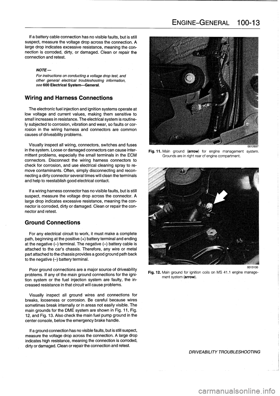
The
main
grounds
for
the
DME
system
are
shown
in
Fig
.
11,Fig
.
12,
and
Fig
.
13
.
Also
check
the
main
fuel
pump
ground
in
the
center
console,
below
the
emergency
brake
handle
.
If
a
ground
connection
has
no
visiblefaults,
but
is
still
suspect,
measure
the
voltage
drop
acrossthe
connection
.
A
large
drop
indicates
high
resistance,
meaning
the
connection
is
corroded,
dirty
or
damaged
.
Clean
or
repair
the
connection
and
retest
.
ENGINE-GENERAL
100-
1
3
UU,~uyi
Fig
.
11
.
Mainground
(arrow)
for
engine
management
system
.
Grounds
are
in
right
rear
of
engine
compartment
.
Fig
.
12
.
Mainground
for
ignition
coils
on
MS
41
.1
engine
manage-
ment
system
(arrow)
.
DRIVEABILITY
TROLIBLESHOOTING
Page 59 of 759
110
Engine
Removal
and
Installation
GENERAL
.
.
.
.
.......
.
.
.
..........
.
...
110-1
Engine,
removing
and
installing
(4-cylinder
engines)
.
..
.....
..
...........
110-1
ENGINE
REMOVAL
AND
INSTALLATION
110-1
Engine,
removing
and
installing
(6-cylinder
engines)
..
...
...
..
.....
..
....
110-4
GENERAL
Some
special
tools
are
required
for
removal
and
installation
of
the
engine
.
Be
sure
to
have
the
necessary
equipment
on
hand
before
starting
thejob
.
CAUTION-
"
Engine
removal
requires
disconnecting
the
bat-
tery
.
This
may
erase
any
system
fault
code(s)
that
havebeen
stored
in
control
unit
memories
.
Check
forfault
codes
prior
to
disconnecting
the
battery
cables
.
"
If
the
Check
Engine
lightis
illuminated
with
the
engine
running,
see
100
Engine-General
for
On-Board
Diagnostics
(08D)
fault
code
infor-
mation
.
"
If
any
other
system
faults
have
been
detected,
as
indicated
by
an
illuminated
ANTI
LOCK,
SRS
or
AST
warning
light,
see
the
appropriate
repair
group
inthis
manual
or
an
authorized
BMW
dealer
for
more
information
on
fault
codes
.
ENGINE
REMOVALAND
INSTALLATION
Engine,
removing
and
installing
(4-cylinder
engines)
Cover
al¡
painted
surfaces
before
beginning
theremoval
procedure
.
Asan
aid
to
installation,
label
al¡
components,
wires,
and
hoses
before
removing
them
.
Do
not
reuse
gas-
kets,
O-rings
or
seals
during
reassembly
.
WARNING
-
Due
to
risk
of
personal
injury,
be
sure
the
engine
is
cold
before
beginning
the
removalprocedure
.
1.
Disconnect
negative
(-)
cable
from
battery
in
luggage
compartment
.
0011969
CAUTION-
Prior
to
disconnecting
the
battery,
read
the
battery
disconnection
cautions
given
at
the
front
of
this
manual
on
page
viii
.
ENGINE
REMOVAL
AND
INSTALLATION
110-1
2
.
Remove
transmission
from
car
.
See230
Manual
Transmission
or
240
Automatic
Transmission
.
3
.
Remove
enginehood
or
place
hood
in
service
positíon
.
See
410
Fenders,
Engine
Hood
.
NOTE-
tt
is
notnecessary
to
remove
the
engine
hood,
but
it
is
helpful
and
will
make
engine
removal
and
installation
easier
.
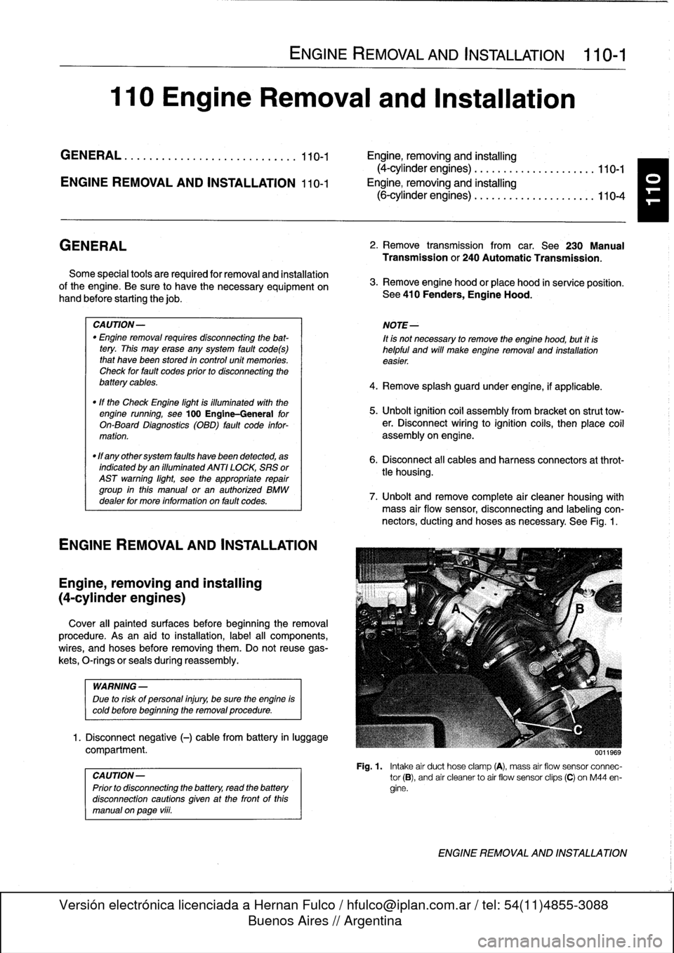
4
.
Remove
splash
guard
under
engine,
if
applicable
.
5
.
Unbolt
ignition
coil
assembly
from
bracket
on
strut
tow-er
.
Disconnect
wiring
to
ignition
cofs,
then
place
coil
assembly
on
engine
.
6
.
Disconnect
al¡
cables
and
harness
connectors
at
throt-
tle
housing
.
7
.
Unbolt
andremove
complete
air
cleaner
housing
with
mass
air
flow
sensor,
disconnecting
and
labeling
con-
nectors,
ducting
and
hoses
asnecessary
.
See
Fig
.
1
.
Fig
.
1
.
Intake
air
duct
hose
clamp
(A),
mass
air
flow
sensor
connec-
tor
(B),
and
air
cleanerto
air
flow
sensor
clips
(C)
on
M44
en-
gine
.
ENGINE
REMOVAL
AND
INSTALLATION
Page 68 of 759
113-2
CYLINDER
HEAD
REMOVAL
AND
INSTALLATION
0011s6i
-
0Fig
.
1
.
Front
exhaust
pipe
to
exhaust
manifold
mountíng
nuts
(arrows)
.
-1
~~
0013023
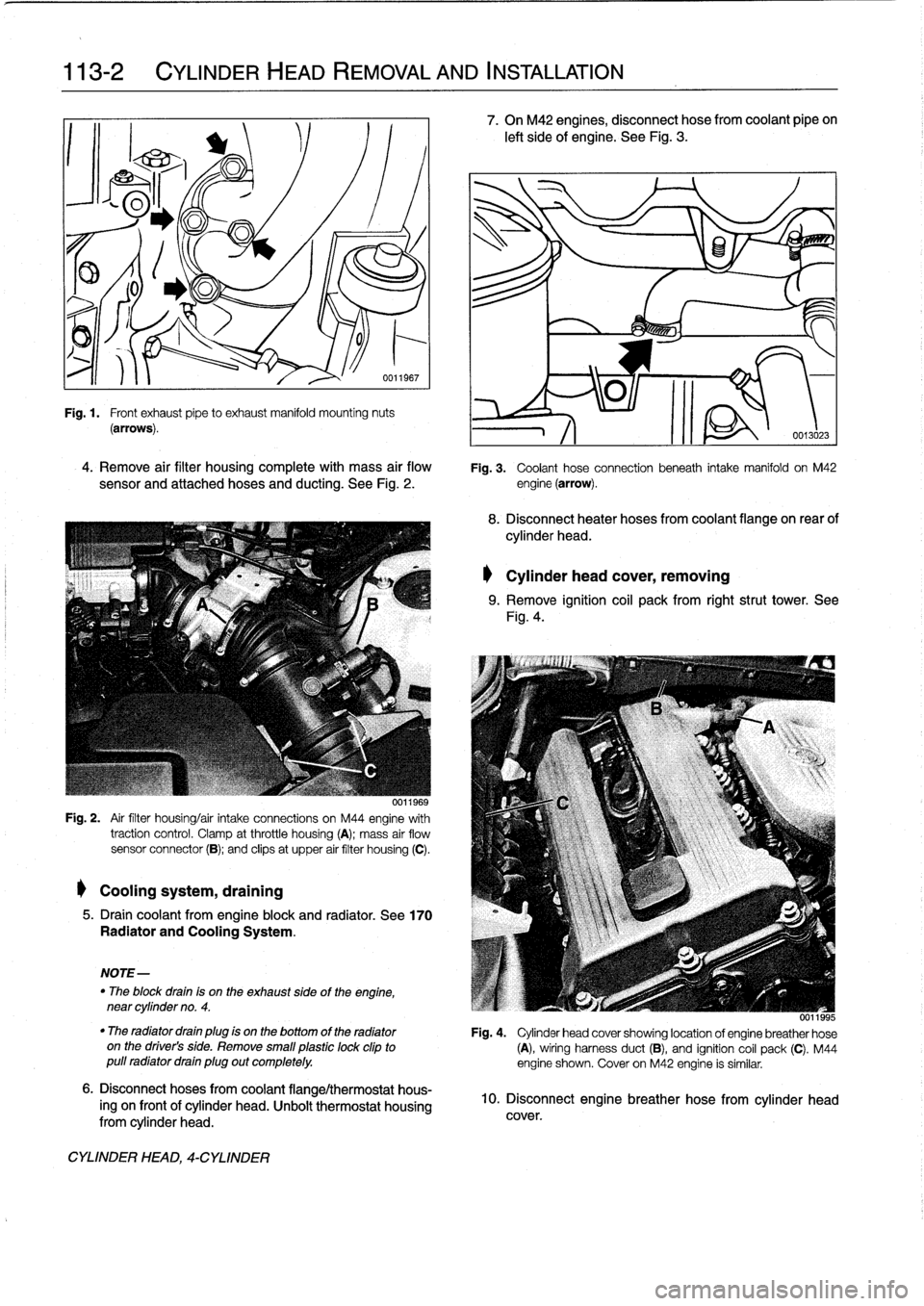
4
.
Remove
air
filter
housing
complete
with
mass
air
flow
Fig
.
3
.
Coolant
hose
connection
beneath
intake
manifold
on
M42
sensor
and
attached
hoses
and
ducting
.
See
Fig
.
2
.
engine
(arrow)
.
0011969
Fig
.
2
.
Air
filter
housing/air
intake
connections
on
M44
engine
with
traction
control
.
Clamp
atthrottle
housing
(A)
;
mass
air
flow
sensor
connector
(B)
;
and
clips
at
upper
air
filter
housing
(C)
.
Coolingsystem,
draining
5
.
Draincoolant
from
engine
block
and
radiator
.
See
170
Radiator
and
Cooling
System
.
NOTE-
"
The
block
drain
is
on
the
exhaust
sideof
the
engine,
near
cylinder
no
.
4
.
6
.
Disconnect
hoses
from
coolant
flange/thermostat
hous-
ing
on
frontof
cylinder
head
.
Unbolt
thermostat
housing
from
cylinder
head
.
CYLINDER
HEAD,
4-CYLINDER
7
.
On
M42
engines,
disconnect
hose
from
coolant
pipe
on
left
side
of
engine
.
See
Fig
.
3
.
8
.
Disconnect
heater
hoses
from
coolant
flange
on
rear
of
cylinder
head
.
Cylinder
head
cover,
removing
9
.
Remove
ignition
coil
pack
from
rightstrut
tower
.
See
Fig
.
4
.
0011995
"
The
radiator
drain
plug
is
on
the
bottomof
the
radiator
Fig
.
4
.
Cylinder
head
cover
showing
location
of
engine
breather
hose
on
the
driver's
side
.
Remove
small
plastic
lock
clipto
(A),
wiring
harness
duct
(B),
and
ignition
coil
pack
(C)
.
M44
pull
radiator
drain
plug
out
completely
.
engine
shown
.
Cover
on
M42
engine
is
similar
.
10
.
Disconnect
engine
breather
hose
from
cylinder
head
cover
.
Page 78 of 759
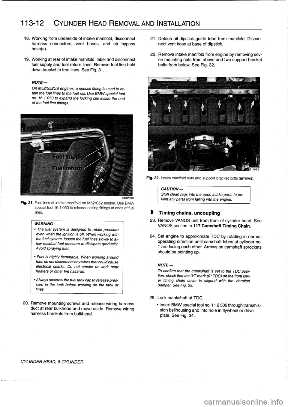
113-12
CYLINDER
HEAD
REMOVAL
AND
INSTALLATION
18
.
Working
from
underside
of
intake
manifold,
disconnect
21
.
Detach
oil
dipstick
guide
tube
from
manifold
.
Disconharness
connectors,
vent
hoses,
and
air
bypass
nectvent
hose
at
base
of
dipstick
.
hoses)
.
22
.
Remove
intake
manifold
from
engine
byremoving
sev-19
.
Working
at
rear
of
intake
manifold,
label
and
disconnect
en
mounting
nuts
from
above
andtwo
support
bracket
fuel
supply
and
fuel
return
lines
.
Remove
fuelline
hold
bolts
from
below
.
See
Fig
.
32
.
down
bracket
to
free
lines
.
See
Fig
.
31
.
NOTE-
On
M52IS52US
engines,
a
special
fitting
is
used
to
re-tain
the
fuel
fines
to
the
fuel
rail
.
Use
BMW
special
tool
no
.
16
1
050
to
expand
the
locking
clip
inside
the
end
of
the
fuellíne
fittings
.
WARNING
-
"
The
fuel
system
is
desígned
to
retan
pressure
even
wheh
the
ignition
is
off
.
When
working
with
the
fuel
system,
loosen
the
fuel
lines
slowly
toal-
low
residual
fuel
pressure
to
dissipate
gradually
.
Avoid
spraying
fuel
.
"
Fuel
is
highly
flammable
.
When
working
around
fuel,
do
not
disconnect
any
wires
that
could
cause
electrfcal
sparks
.
Do
not
smoke
orwork
near
heaters
or
other
fire
hazards
.
"
Always
unscrew
the
fuel
tank
cap
to
release
pres-
sure
in
the
tank
before
working
on
the
tank
or
lines
.
20
.
Remove
mountingscrews
and
release
wiring
harness
duct
at
rear
bulkhead
and
move
aside
.
Remove
wiring
harness
brackets
frombulkhead
.
CYLINDER
HEAD,
6-CYLINDER
Fig
.
32
.
Intake
manifoldnuts
and
support
bracket
bolts
(arrows)
.
CAUTION-
Stuff
clean
rags
into
the
open
intake
ports
topre-
001269s
vent
any
ports
from
falfing
into
the
engine
.
Fig
.
31
.
Fuel
lines
at
intake
manifold
on
M52/S52
engine
.
Use
BMW
special
tool
16
1
050
to
release
locking
fittings
at
ends
of
fuel
enes
.
1
Timing
chains,
uncoupling
23
.
Remove
VANOS
unit
from
frontof
cylinder
head
.
See
VANOS
section
in
117
Camshaft
Timing
Chain
.
24
.
Setengine
to
approximate
TDC
by
rotating
in
normal
operating
direction
until
camshaft
lobes
at
cylinder
no
.
1
are
facing
each
other
.
Arrows
on
camshaft
sprockets
should
be
pointing
up
.
NOTE-
To
confirm
that
the
crankshaft
is
set
to
the
TDC
posi-
tion,
check
that
the
OIT
mark
(0°
TDC)on
the
front
low-
er
timing
chain
cover
ís
aligned
with
the
víbration
damperSee
Fig
.
33
.
25
.
Lock
crankshaft
at
TDC
.
"
Insert
BMW
special
tool
no
.
11
2
300
through
transmis-
sion
bellhousing
and
finto
hole
in
flywheelor
drive
plate
.
See
Fig
.
34
.
Page 116 of 759
119-2
LUBRICATION
SYSTEM
NOTE-
Component
Location
If
the
light
does
not
go
out,
thewiring
to
theswitch
is"
Oil
pressure
switch
most
likely
grounded
somewhere
between
the
switch
all
engines
.......
...
.
..
......
ora
oil
filter
housing
terminal
and
the
warning
light
.
Sea
Electrical
Wiring
Diagrams
atrearof
manual
for
electrical
schematics
.
CAUTION-
Some
oil
may
drain
out
as
the
oil
pressure
switch
is
removed
.
Use
a
rag
to
soak
up
any
spills
.
2
.
Install
pressure
gauge
in
place
of
switch
.
3
.
With
gauge
instalied,
start
engine
and
allow
to
reach
operating
temperature
.
Check
oil
pressureboth
cold
and
hot
.
NOTE-
For
the
most
accurate
test
results,
the
engine
oil
(and
filter)
shouldbe
newand
of
the
correct
grade
.
Oil
Pressure
"
¡dle
(mínimum)
..
.
.
..............
.
.
0
.5
bar
(7psi)
"
Regulated
pressure
(elevated
engine
speed)
4-cylinder
engines
..
......
4
.3
±
0
.2
bar
(63
t3
psi)
6-cylinder
engines
.
.
.............
.
4
.0
bar
(59
psi)
4
.
Remove
pressure
gauge
and
reinstall
pressure
switch
.
If
testing
shows
low
oil
pressure,
one
or
more
of
the
follow-
ing
conditions
may
be
indicated
:
OIL
PAN
"
Worn
or
faulty
oii
pump
.
"
Worn
or
faulty
engine
bearings
The
oil
pancan
be
removed
with
the
engine
instalied,
al-
Severe
engine
wear
.
though
specíal
enginesupport
equipment
will
be
needed
.
Al¡
of
these
conditionsindicate
the
need
for
major
repairs
.
Oil
pressure
warning
system,
testing
When
the
ignition
is
tumed
ora,
the
oil
pressure
warning
light
comes
ora
.
When
the
engine
ís
started
and
the
oil
pressure
ris-
es
slightly,
the
oil
pressure
switch
opens
and
thewarning
light
goes
out
.
Make
sure
the
oil
leve¡
is
correct
before
making
tests
.
1
.
Turra
ignition
switch
ora
.
"
Warning
light
ora
instrument
panel
must
light
up
.
2
.
Remove
connector
from
oil
pressure
switch
.
"
Warning
light
ora
instrument
panel
must
go
out
.
OIL
PAN
3
.
If
warning
light
does
not
light
when
ignition
is
ora,
re-
move
connector
from
oil
pressure
switch
anduse
a
jumper
wire
to
ground
connector
terminal
to
a
clean
metal
surface
.
NOTE
-
If
the
warning
light
comes
ora,
check
the
switch
as
de-
scríbed
in
the
nextstep
.
If
the
warning
light
does
not
come
ora,
thewiring
to
the
instrument
cluster
or
to
the
light
itself
isfaulty
.
4
.
To
test
switch,
connect
ara
ohmmeter
between
terminal
in
switch
body
and
ground
.
With
engine
off,
these
should
be
continuity
.
With
engine
running,
oil
pressure
should
opera
switch
and
there
should
beno
continuity
Replace
a
faulty
switch
.
WARNING
-
Keep
in
mind
that
low
oil
pressure
may
be
prevent-
ing
the
switch
from
tuming
the
light
out
.
If
the
light
remains
ora
while
the
engine
is
running,
check
the
oil
pressure
asdescribed
earlier
.
Do
not
drive
the
car
until
the
problem
is
corrected
.
Theengine
may
be
severely
damaged
.
Oil
pan,
removing
and
installing
(4-cylinder
engines)
1
.
Raise
car
arad
place
securely
ora
jackstands
.
2
.
Remove
splash
shíeld(s)
from
under
engine,
where
ap-
plicable
.
3
.
Drain
engine
oil
as
described
in
020
Maintenance
Pro-
gram
.
4
.
Disconnect
vacuum
hose
adapter
from
vacuum
brake
booster
at
rear
of
engine
compartment
.
5
.
Remove
oil
dipstick
guide
tube
mounting
nut
and
pull
guide
tube
from
oil
pan
.
See
Fig
.
2
.