Subframe BMW 318i 1992 E36 Workshop Manual
[x] Cancel search | Manufacturer: BMW, Model Year: 1992, Model line: 318i, Model: BMW 318i 1992 E36Pages: 759
Page 61 of 759
14
.
Unbolt
power
steering
fluid
reservoir
from
íts
mounting
bracket
.
Use
stiff
wire
to
hang
reservoir
to
one
side
.
Do
not
disconnect
fluid
lines
.
15
.
Remove
power
steering
pump
drive
belt
and
remove
pump
from
its
mounting
bracket
.
Use
stiff
wire
to
hang
pump
from
body
.
16
.
On
cars
with
automatic
transmission
remove
front
and
rear
brackets
holding
automatic
transmission
cooler
linesto
engine
.
17
.
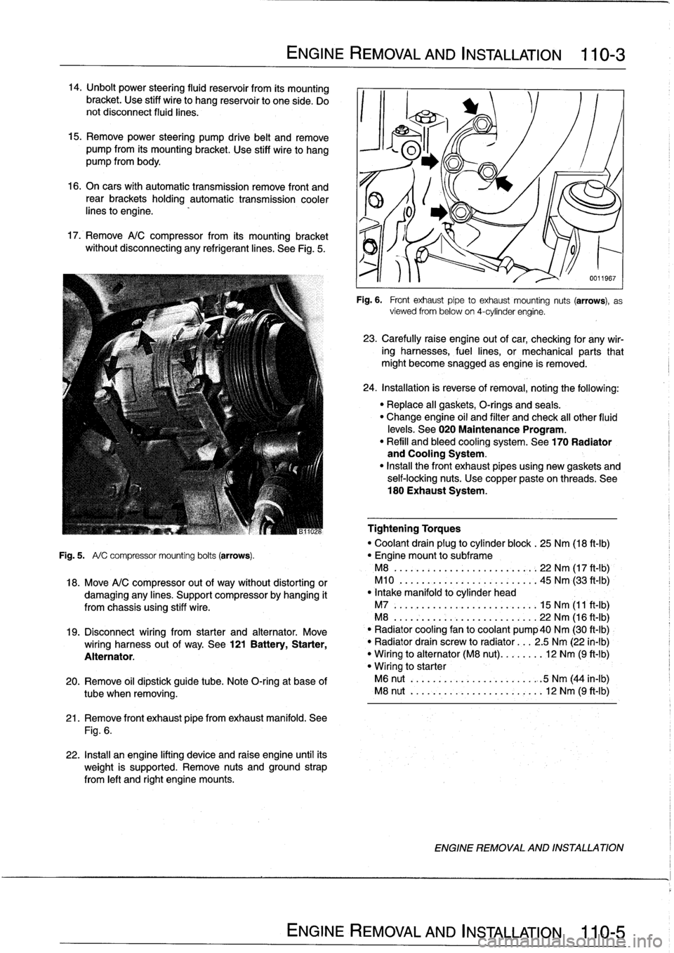
Remove
A/C
compressor
from
its
mounting
bracket
without
disconnecting
any
refrigerantlines
.
See
Fig
.
5
.
ENGINE
REMOVAL
AND
INSTALLATION
110-
3
21
.
Remove
front
exhaust
pipefrom
exhaust
manifold
.
See
Fig
.
6
.
22
.
Install
an
engine
lifting
device
and
raise
engine
until
its
weight
is
supported
.
Remove
nuts
and
ground
strap
from
left
and
right
engine
mounts
.
0011967
Fig
.
6
.
Front
exhaustpipe
to
exhaust
mounting
nuts
(arrows),
as
viewed
from
below
on
4-cylinder
engine
.
23
.
Carefully
raíse
engine
out
of
car,
checking
for
any
wir-
ing
harnesses,
fuel
lines,
or
mechanical
parts
that
might
become
snagged
as
engine
is
removed
.
24
.
Installation
is
reverse
of
removal,
noting
the
following
:
"
Replace
all
gaskets,
O-rings
and
seals
.
"
Change
engine
oil
and
filter
and
check
al¡
other
fluid
levels
.
See020
Maintenance
Program
.
"
Refill
and
bleed
cooling
system
.
See
170
Radiator
and
Cooling
System
.
"
Insta¡¡
the
front
exhaust
pipes
using
new
gaskets
and
self-locking
nuts
.
Use
copper
pasteon
threads
.
See
180
Exhaust
System
.
Tightening
Torques
"
Coolant
drain
plug
to
cylinder
block
.
25
Nm
(18
ft-Ib)
Fig
.
5
.
A/
C
compressor
mounting
bolts
(arrows)
.
"
Engine
mount
to
subframe
M8
......:...
..
..
..
......,:..
22
Nm
(17
ft
-
1b)
,
18
.
Move
A/C
compressor
out
of
way
without
distorting
or
M10
.
...
.
..
...
.
.
...........
45
Nm
(33
ft'-Ib)
damaging
any
lines
.
Support
compressor
by
hanging
it
"
Intake
manifold
to
cylinder
head
from
chassis
using
stiff
wire
.
M7
.....
.
..
...
..
..
...........
15
Nm
(11
ft-Ib)
M8
...
.
.
.
..
..
...
..
...........
22
Nm
(16
ft-Ib)
19
.
Disconnect
wiring
from
starter
and
alternator
.
Move
`
"
Radiator
cooling
fan
to
coolant
pump40
Nm
(30
ft-Ib)
wiring
harness
out
of
way
.
See
121
Battery,
Starter,
"
Radiator
drain
screw
to
radiator
...
2
.5
Nm
(22
in-lb)
Alternator
.
"
Wiring
to
alternator
(M8
nut)
........
12
Nm
(9
ft-1b)
"
Wiring
to
starter
20
.
Remove
oil
dipstick
guide
tube
.
Note
O-ring
at
base
of
M6
nut
..
.
..
..
...
..
...........
.
:5
Nm
(44
in-lb)
tube
when
removing
.
M8
nut
..
.
..
..
...
..
............
12
Nm
(9
ft-Ib)
ENGINE
REMOVAL
AND
INSTALLATION
Page 65 of 759
22
.
Move
A/C
compressor
out
of
the
way
without
distorting
26
.
Carefully
raise
engine
out
ofcar,
checking
for
any
wir-
or
damaging
any
lines
.
Support
compressor
by
hanging
ing,fuel
lines,
or
mechanical
parts
that
might
become
it
from
chassis
using
stiff
wire
.
snagged
as
engine
is
removed
.
23
.
Disconnect
wiring
from
starter
and
alternator
.
Move
27
.
Installation
is
reverse
of
removal,
noting
the
following
:
wiring
harness
out
of
the
way
.
See
121
Battery,
Start-
Replace
al¡
gaskets,
O-rings
and
seals
.
er,
Alternator
.
"
Change
engine
oil
and
filter
and
check
all
other
fluid
24
.
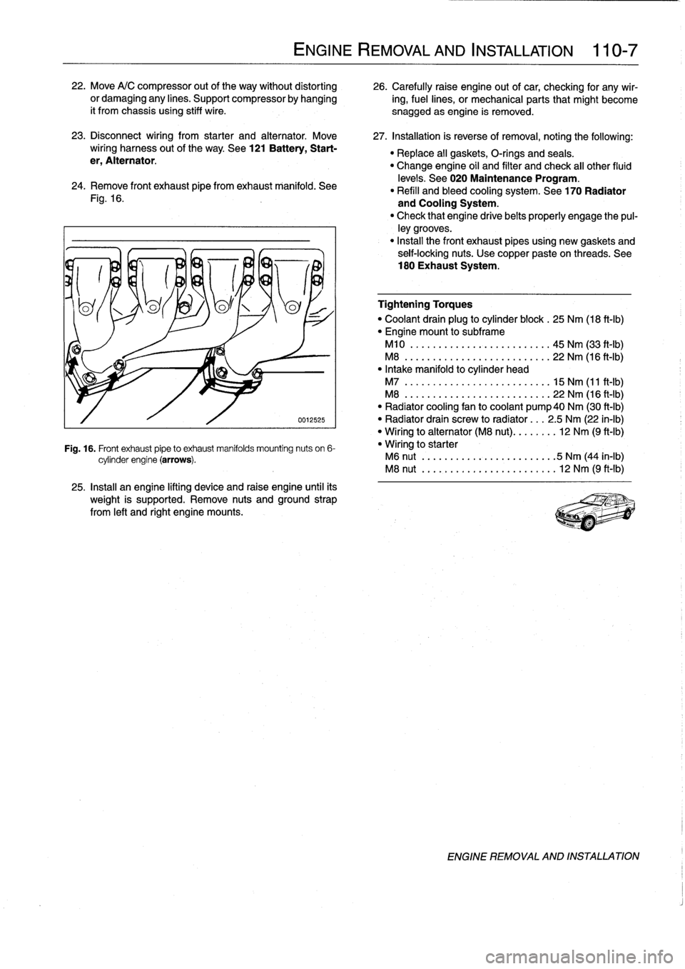
Remove
Fontexhaust
pipe
fromexhaust
manifold
.
See
levels
.
See
020
Maintenance
Program
.
"
Refill
and
bleed
cooling
system
.
See
170
Radiator
Fig
.
16
.
and
Cooling
System
.
"
Check
that
engine
drivebelts
properly
engage
the
pul-
ley
grooves
.
"
Install
the
Font
exhaust
pipesusing
new
gaskets
and
seif-locking
nuts
.
Use
copper
paste
on
threads
.
See
180
Exhaust
System
.
0012525
Fig
.
16
.
Front
exhaust
pipeto
exhaust
manifolds
mounting
nuts
on
6-
cylinder
engine
(arrows)
.
25
.
Install
an
engine
lifting
device
and
raise
engine
until
its
weight
is
supported
.
Remove
nuts
and
ground
strap
from
left
and
right
engine
mounts
.
ENGINE
REMOVAL
AND
INSTALLATION
110-
7
Tightening
Torques
"
Coolant
drain
plug
to
cylinder
block
.
25
Nm
(18
ft-Ib)
"
Engine
mount
to
subframe
M10
..
.
.
.
...
..............
..
.
45
Nm
(33
ft-Ib)
M8
..
..
.
..
................
...
22
Nm
(16
ft-Ib)
"
Intake
manifold
to
cylinder
head
M7
..
..
..
...
................
.
15
Nm
(11
ft-Ib)
M8
...
.
..
...
................
.
22
Nm
(16
ft-Ib)
"
Radiator
cooling
fan
to
coolant
pump40
Nm
(30
ft-Ib)
"
Radiator
drain
screw
to
radíator
...
2
.5
Nm
(22
in-lb)
"
Wiring
to
alternator
(M8
nut)
........
12
Nm
(9
ft-Ib)
"
Wiring
to
starter
M6
nut
.
..
...
..................
5
Nm
(44
in-lb)
M8
nut
.....
..
.
.
.
.
.............
12
Nm
(9
ft-Ib)
ENGINE
REMOVAL
AND
INSTALLATION
Page 117 of 759
NOTE
-
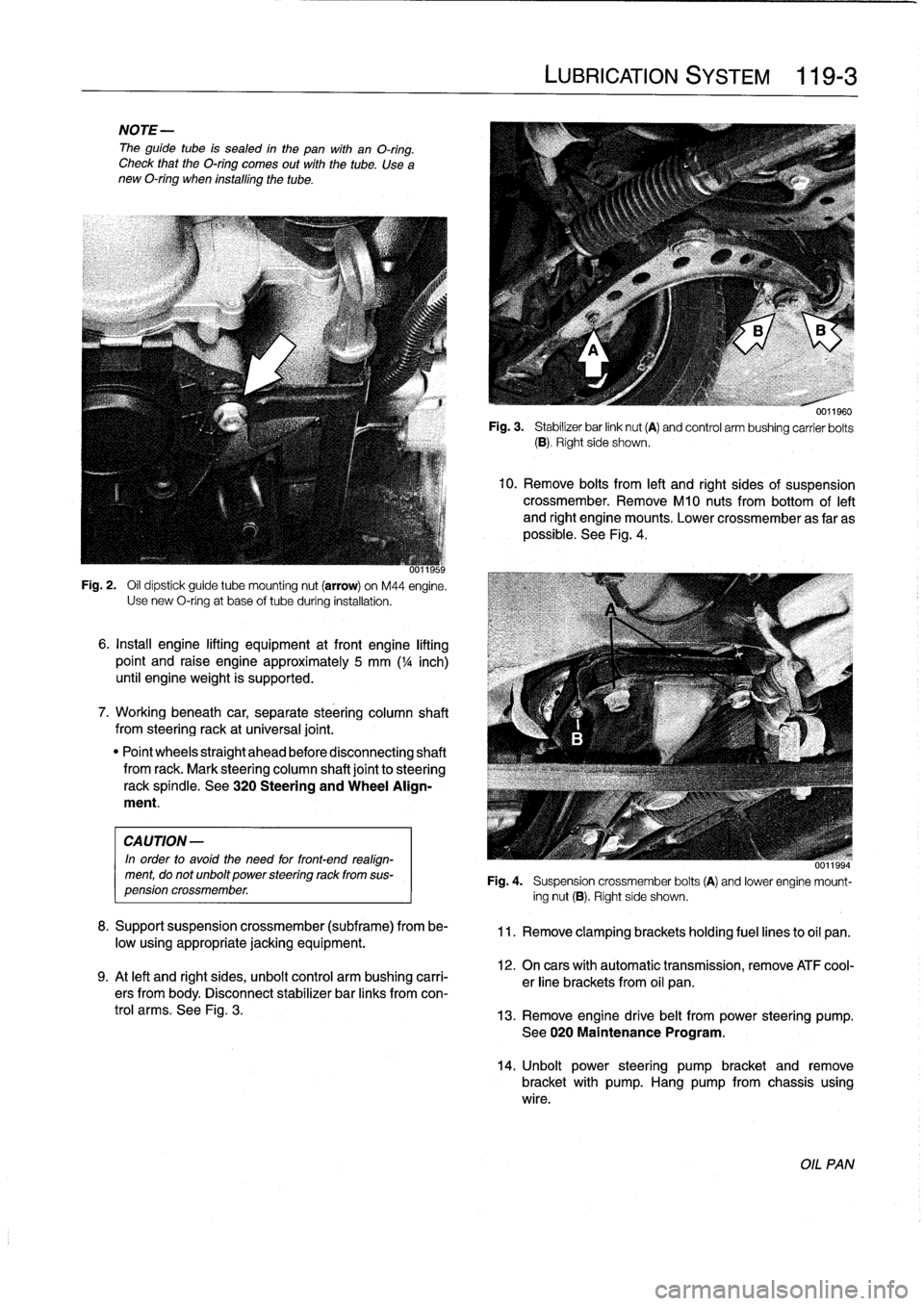
The
guide
tube
is
sealed
in
the
pan
with
an
O-ring
.
Check
that
theO-ring
comes
out
with
the
tube
.
Use
a
new
O-ring
when
installing
the
tube
.
Fig
.
2
.
Oil
dipstick
guide
tube
mounting
nut
(arrow)
on
M44
engine
.
Use
new
O-ring
at
base
of
tube
during
installatidn
.
6
.
Install
engine
lifting
equipment
at
front
engine
lifting
point
and
raise
engine
approximately
5
mm
(
1
/4
inch)
until
engineweight
is
supported
.
7
.
Workingbeneath
car,
separate
steering
column
shaft
from
steeringrack
at
universal
joint
.
"
Point
wheels
straight
ahead
before
disconnecting
shaft
from
rack
.
Mark
steering
column
shaft
joint
to
steering
rackspíndle
.
See
320
Steering
and
Wheel
Align-
ment
.
CAUTION
-
In
order
to
avoíd
the
need
for
front-end
realign-
ment,
do
notunbolt
power
steering
rack
from
sus-
pension
crossmember
.
8
.
Supportsuspension
crossmember
(subframe)
from
be-
low
usingappropriate
jacking
equipment
.
9
.
At
left
and
right
sides,
unbolt
control
arm
bushing
carri-
ers
from
body
.
Disconnect
stabilizer
bar
links
fromcon-
trol
arms
.
See
Fig
.
3
.
LUBRICATION
SYSTEM
119-
3
0011960
Fig
.
3
.
Stabilizer
bar
link
nut
(A)
and
control
arm
bushing
carrier
bolts
(B)
.
Right
side
shows
.
10
.
Remove
bolts
from
left
and
right
sides
of
suspension
crossmember
.
RemoveM10
nuts
from
bottom
of
left
and
right
engine
mounts
.
Lower
crossmember
as
far
as
possible
.
See
Fig
.
4
.
uu1ibb4
Fig
.
4
.
Suspension
crossmember
bolts
(A)
and
lower
engine
mount-
ing
nut
(B)
.
Right
side
shows
.
11
.
Remove
clamping
brackets
holding
fuel
lines
to
oil
pan
.
12
.
On
cars
with
automatic
transmission,
remove
ATF
cool-
er
line
brackets
from
oil
pan
.
13
.
Remove
engine
drive
belt
from
power
steering
pump
.
See020
Maintenance
Program
.
14
.
Unbolt
power
steering
pumpbracket
andremove
bracket
with
pump
.
Hang
pump
from
chassis
using
wire
.
OIL
PAN
Page 118 of 759
119-
4
LUBRICATION
SYSTEM
15
.
Remove
oil
pan
screws
.
Lower
andremove
oil
pan
to-
ward
rear
.
Tightening
Torques
"
Control
arm
bushing
carrier
CAUTION-
to
body(M10
bolt)
...............
42
Nm
(31
ft-Ib)
'
lf
the
oil
pan
does
not
separate
easily
from
the
en-
"
Engine
mount
to
gine
cylinder
block,
make
sure
all
mounting
bolis
suspension
crossmember
(M10
nut)
.
42
Nm
(31
ft-Ib)
have
been
removed
.
If
necessary,
a
few
tapswith
"
Front
suspension
crossmember
a
rubber
mallet
shouldbreak
it
free
.
Never
pry
the
to
body
.
.
..
...
..
.
....
See
310
Front
SusPension
oil
pan
loose
.
"
Oil
pan
to
engine
block
(M6
bolt)
8
.8
grade
..
....
.
...
...
.
........
10
Nm
(89
in-lb)
16
.
Installation
is
reverse
of
removal
.
10
.9
grade
...
..
.
....
..
.
.
.
.......
12
Nm
(9
ft-Ib)
"
Thoroughly
clean
all
old
gasket
material
from
mating
"
Power
steering
pump
to
bracket
surfaces
anduse
a
new
gasket
.
(self-locking
nuts)
....
..
.
....
..
.
..
22
Nm
(16
ft-Ib)
"
Applya
small
amount
of
non-hardening
sealer
(3-
"
Power
steering
pump
bracket
to
engine
Bond
O
l209
or
equivalent)
to
oil
pan
gasket
directly
block
or
oil
pan
(self-locking
nuts)
..
.
22
Nm
(16
ft-Ib)
below
joints
for
end
cover
and
front
timing
case
cover
.
"
Stabilizer
bar
link
to
control
arm
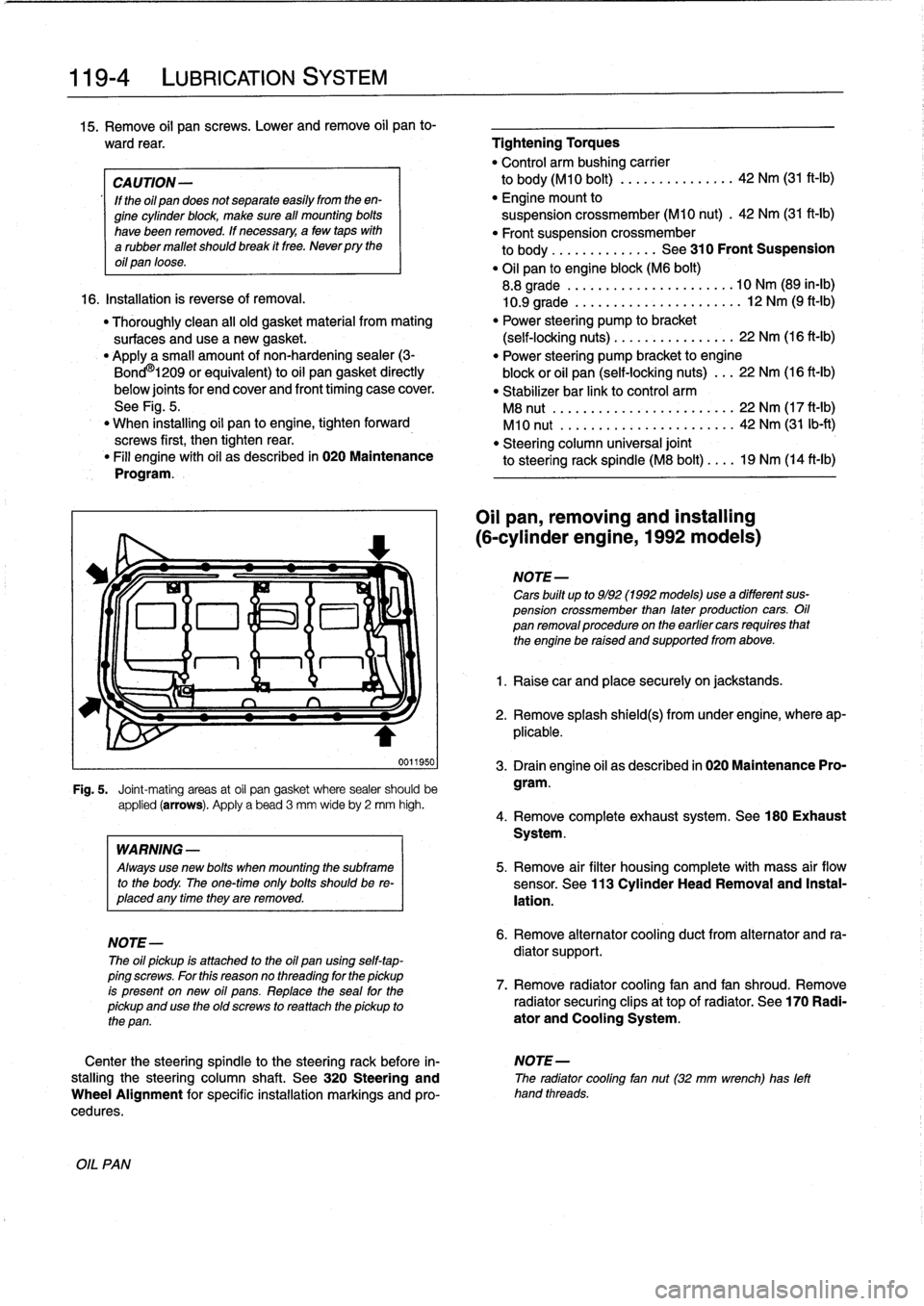
See
Fig
.
5
.
M8
nut
.................
...
.
...
22
Nm
(17
ft-Ib)
"
When
installing
oil
pan
to
engine,
tighten
forward
M10
nut
.....................
..
42
Nm
(31
Ib-ft)
screws
first,
then
tightenrear
.
"
Steering
column
universal
joint
"
Fill
engine
with
oil
as
described
in
020
Maintenance
to
steering
rack
spindle
(M8
bolt)
....
19
Nm
(14
ft-ib)
Program
.
0011950
Fig
.
5
.
Joint-mating
areas
at
oil
pan
gasket
where
sealer
should
be
applied
(arrows)
.
Apply
a
bead
3
mm
wideby
2
mm
high
.
OIL
PAN
WARNING
-
Always
use
new
bolis
when
mounting
the
subframe
to
the
body
.
The
one-timeonly
bolis
shouldbe
re-
placed
any
timethey
are
removed
.
NOTE-
The
oil
pickup
is
attached
to
the
oil
pan
using
self-tap-
ping
screws
.
For
this
reasonno
threading
for
the
pickup
is
present
on
new
oil
pans
.
Replace
the
seal
for
the
pickup
and
use
the
oíd
screws
to
rea
ttach
the
pickup
to
the
pan
.
Oil
pan,
removing
and
installing
(6-cylinder
engine,
1992models)
NOTE-
Cars
built
up
to
9/92
(1992models)usea
different
sus-
pension
crossmember
than
later
production
cars
.
Oil
pan
removalprocedureon
the
earlier
cars
requires
that
the
engine
be
raised
and
supportedfrom
above
.
1
.
Raise
car
and
place
securely
on
jackstands
.
2
.
Remove
splash
shield(s)
from
under
engine,
where
ap-
plicable
.
3
.
Drain
engine
oil
as
described
in
020
Maintenance
Pro-
gram
.
4
.
Remove
complete
exhaust
system
.
See180
Exhaust
System
.
5
.
Remove
air
filter
housing
complete
with
mass
air
flow
sensor
.
See
113
Cylinder
Head
Removal
and
Instal-
lation
.
6
.
Remove
alternator
cooling
duct
from
alternator
and
ra-
diator
support
.
7
.
Remove
radiator
cooling
fan
and
fan
shroud
.
Remove
radiator
securing
clips
at
top
of
radiator
.
See
170
Radi-
ator
and
Cooling
System
.
Center
the
steering
spindle
to
the
steering
rack
before
in-
NOTE-
stalling
the
steering
column
shaft
.
See
320
Steering
and
The
radiator
cooling
fan
nut(32
mm
wrench)
has
left
Wheel
Alignment
for
specific
installation
markings
and
pro-
hand
threads
.
cedures
.
Page 120 of 759
119-
6
LUBRICATION
SYSTEM
17
.
Raise
engine
as
much
as
possible
.
Check
carefully
for
22
.
Installation
is
reverse
of
removal
.
obstructions,
wiring
harness
clearance
and
pinched
hoses
or
lines
as
engine
is
raised
.
"
When
installing
oil
pan,
apply
a
b
d
of
non-hardening
sealing
compound
(3-Bond
1209
0
or
equivalent)
to
18
.
Remove
oil
pan
mounting
bolts
and
lower
oil
pan
to
front
and
rear
end
cover
seam
areas
on
block
.
subframe
crossmember
.
"
Position
oil
pump
pickup
tube
and
oil
pan
onto
block
and
install
pickup
tube
using
a
new
gasket
.
"
Be
sure
tab
on
gasket
faces
down
towards
intake
of
NOTE-
pickup
tube
.
If
the
oil
pan
does
not
separate
easily
from
the
engine
"
Tightenforward
oil
pan
screws
first,
then
tighten
rear
.
cylinder
block,
afew
taps
with
arubber
mallet
should
"
Fill
engine
with
oil
as
described
in
020
Maintenance
break
it
free
.
Do
not
pry
the
oil
pan
loose
.
Program
.
"
After
adding
engine
oil,
start
and
run
engine
.
Raise
en-
19
.
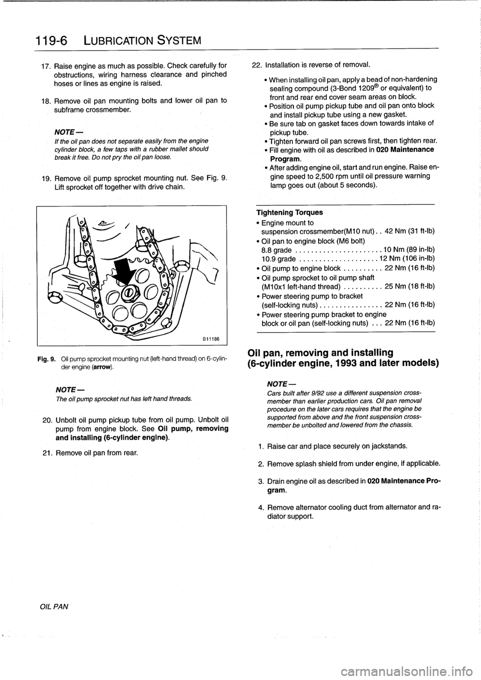
Remove
oil
pump
sprocket
mounting
nut
.
See
Fig
.
9
.
gine
speed
to
2,500
rpm
until
oil
pressure
warning
Lift
sprocket
off
together
with
drive
chain
.
lampgoes
out(about
5seconds)
.
Fig
.
9
.
Oil
pump
sprocket
mounting
nut
(left-hand
thread)
on
6-cylin-
OII
pan,
removing
and
installing
derengine(arrow)
.
(6-cylinder
engine,
1993
and
later
modeis)
NOTE-
The
oíl
pump
sprocket
nut
has
left
hand
threads
.
20
.
Unbolt
oil
pump
pickup
tubefrom
oil
pump
.
Unbolt
oil
pump
from
engine
block
.
See
Oil
pump,
removing
and
installing
(6-cylinder
engine)
.
21
.
Remove
oil
pan
from
rear
.
Tightening
Torques
"
Engine
mount
to
suspension
crossmember(M10
nut)
..
42
Nm
(31
ft-Ib)
"
Oil
pan
to
engine
block
(M6
bolt)
8
.8
grade
....
..
.
...
...
.
........
10
Nm
(89
in-lb)
10
.9
grade
.
.
..
.
..
...
.
.
.
.
.
.....
12
Nm
(106
in-lb)
"
Oil
pump
to
engine
block
.
...
...
.
..
22
Nm
(16
ft-Ib)
"
Oil
pump
sprocket
to
oil
pump
shaft
(M1
0x1
left-hand
thread)
...
..
.
.
..
.
25
Nm
(18
ft-Ib)
"
Power
steering
pump
to
bracket
(self-locking
nuts)
.....
.
....
..
.
...
22
Nm
(16
ft-lb)
"
Power
steering
pump
bracket
to
engine
block
or
oil
pan
(self-locking
nuts)
.
..
22
Nm
(16
ft-Ib)
NOTE-
Cars
built
after
9/92
use
a
different
suspension
cross-
member
¡han
earfier
productíon
cars
.
Oil
pan
removal
procedure
on
the
later
cars
requíres
that
the
engine
be
supported
from
aboye
and
the
front
suspension
cross-
member
be
unbolted
and
loweredfrom
the
chassis
.
1
.
Raisecar
and
place
securely
on
jackstands
.
2
.
Remove
splash
shield
fromunder
engine,
if
applicable
.
3
.
Drain
engine
oil
as
descríbed
in
020
Maintenance
Pro-
gram
.
4
.
Remove
alternator
cooling
duct
from
alternator
and
ra-
diator
support
.
Page 249 of 759
SUSPENSION,
STEERING
ANDBRAKES-GENERAL
300-1
300
Suspension,
Steering
and
Brakes-General
GENERAL
.....
.
....
.
.....
.
.
.
........
.300-1
M3
SUSPENSION
AND
BRAKES
.......
.
...
300-7
Front
Suspension
..........
.
.
.
...
.
.....
300-1
Steering
...
.
.
.
.
.
....
.
.
.
...
.
.
.
...
.
...
.
.
300-2
SUSPENSION
AND
STEERING
Rear
Suspension
....
.
.
.
...
.
.
.
...
.
.....
300-2
TROUBLESHOOTING
..
.
.
.
.............
300-7
Brakes
.
.
.
.
.
.
.
.
....
.
...........
.
.
.
.
.
.
300-2
Tires
and
wheeis
.
................
.
.
.
.
.
.
300-2
TABLE
a
.
AST
Indicator
Lamp
Function
..
..
.
..
.
.........
300-5
INTEGRATED
SYSTEMS
.........
.
.
.
.
.
.
300-2
b
.
Suspension
and
Steering
Troubleshooting
......
.300-8
Antilock
Brake
System
(ABS)
.......
.
.
.
.
.
.
300-2
Al¡
Season
Traction
(AST)
.........
.
.
.
.
.
.
300-4
GENERAL
Front
Suspension
This
section
covers
general
information
for
front
and
rear
The
lower
control
arms
connect
the
front
suspension
struts
suspension,
the
steering
system,
and
the
brakíng
and
traction
to
mounting
points
on
the
subframe
crossmember
and
the
control
systems
.
body
.
See
Fig
.
2
.
The
BMW
E36
suspension
and
steering
systems
are
engi-
neered
to
provide
a
compromise
between
taut,
responsive
handling
and
ride
comfort
.
Although
the
front
and
rear
suspen-
sion
assemblies
are
independent
subsystems,
they
work
to-
gether
to
achieve
BMW's
overall
combination
of
precise
handling
and
comfort
.
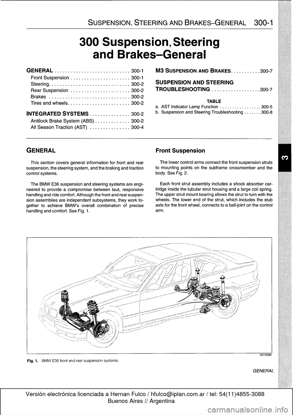
See
Fig
.
1
.
Fig
.
1
.
BMW
E36
front
and
rear
suspension
systems
.
Each
front
strut
assembly
includes
a
shock
absorber
car-
tridgeinside
the
tubular
strut
housing
and
a
large
coil
spring
.
The
upper
strut
mount
bearing
allows
the
strutto
turnwith
the
wheels
.
The
lower
end
of
the
strut,
which
includes
the
stub
axle
for
the
front
wheel,
connects
to
a
ball-joint
on
the
control
arm
.
0013098
GENERAL
Page 257 of 759
GENERAL
310
Front
Suspension
GENERAL
..
.
.
.
.
.
.
.
.
.
.......
.
........
.
310-1
FRONT
WHEEL
BEARINGS
..
.
.
.
.......
310-8
SHOCK
ABSORBERS
AND
SPRINGS
..
.
310-2
Front
wheel
bearing,
replacing
...
.
.
.
.
.
.
.
...
310-8
Strut
assembly,
removing
and
installing
.....
310-2
STABILIZER
BAR
..........
.
.
.
.
.
.
.
.
.
.
.
.
310-9
Strut
assembly,
disassembling
Stabilizerbar,
removing
and
installing
.
.
.
.
...
310-9
and
assembling
.
.
.
...
.
.....
.
.........
310-4
Ride
Height
.
.
.
.
.
.
.
.
.
.
.
.
.....
.
........
.
310-4
SUBFRAME
CROSSMEMBER
.
.
.
.
.
.
.
.
.
.
.
310-9
Subframe
crossmember,
CONTROL
ARMS
.
.
...
.
.
.
.
.
.
.
...
.
.....
310-5
removing
and
installing
.....
.
.
.
.
.
.
.
.
.
...
310-9
Control
arm,
removing
and
installing
....
..
310-5
Outer
control
arm
ball
joint,
replacing
Table
exce
t
M3
models
310-6
a
.
Front
Ride
Height
Specifications
..
.
.....
..
.
..
..
310-5
Control
arm
bushing,
replacing
.
.
.
...
.
.....
310-7
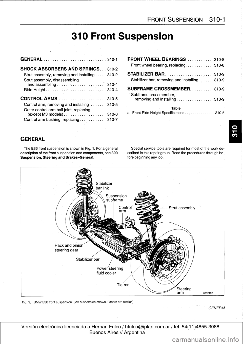
The
E36
front
suspension
is
shown
in
Fig
.
1
.
For
a
general
Specialservice
tools
arerequired
for
most
of
the
work
de-
description
of
the
front
suspension
and
components,
see
300
scribed
in
this
repair
group
.
Read
the
procedures
through
be-
Suspension,
Steering
and
Brakes-General
.
fore
beginning
any
job
.
Stabilizer
bar
Power
steering
fluid
cooler
Control
Strut
assembly
arm
Tierod
Fig
.
1
.
BMW
E36
front
suspension
.
(M3
suspension
shown
.
Others
are
similar
.)
FRONT
SUSPENSION
310-1
Steering
arm
0012132
GENERAL
Page 262 of 759
310-
6
FRONT
SUSPENSION
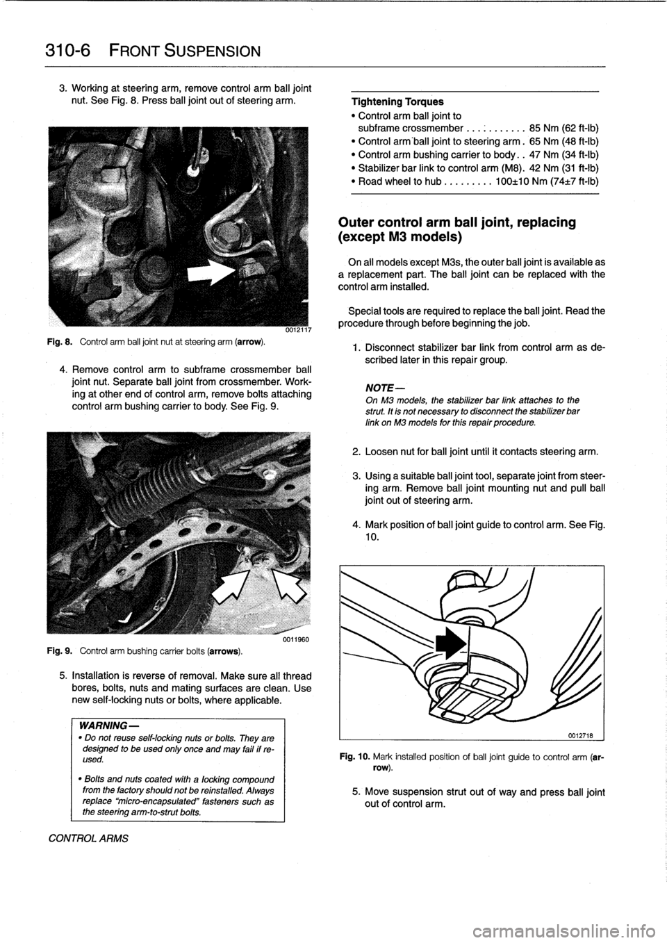
3
.
Working
at
steering
arm,
remove
control
arm
balljoint
nut
.
See
Fig
.
8
.
Press
ball
joint
out
ofsteering
arm
.
Fig
.
8
.
Control
arm
ball
joint
nut
at
steering
arm
(arrow)
.
4
.
Remove
control
arm
to
subframe
crossmember
ball
joint
nut
.
Separate
ball
joint
from
crossmember
.
Work-
ing
at
other
end
of
control
arm,
remove
bolts
attaching
control
arm
bushing
carrier
to
body
.
See
Fig
.
9
.
Fig
.
9
.
Control
arm
bushing
carrier
bolts
(arrows)
.
0012117
0011960
5
.
Installation
is
reverse
of
removal
.
Make
sure
al¡
thread
bores,
bolts,
nuts
and
mating
surfaces
are
clean
.
Use
new
self-locking
nutsor
bolts,
where
applicable
.
WARNING-
"
Do
not
reuse
self-locking
nuts
or
bolts
.
They
are
designed
to
be
used
only
once
and
may
failif
re-
used
.
"
Bolts
and
nuts
coated
with
a
focking
compound
from
the
factory
shouldnot
be
refnstalled
.
Always
replace`micro-encapsulated"
fasteners
such
as
the
steering
arm-to-strutbolts
.
CONTROL
ARMS
Tightening
Torques
"
Control
arm
balljoint
to
subframe
crossmember
.
..
...
...
.
.
85
Nm
(62
ft-Ib)
"
Control
arm'ball
joint
to
steering
arm
.
65
Nm
(48
ft-Ib)
"
Control
arm
bushing
carrier
to
body
.
.
47
Nm
(34
ft-Ib)
"
Stabilizer
bar
link
to
control
arm
(M8)
.
42
Nm
(31
ft-Ib)
"
Road
wheel
to
hub
.
...
...
.
.
100±10
Nm
(74±7
ft-Ib)
Outer
control
arm
ball
joint,
replacing
(except
M3
models)
On
all
models
except
Mas,
the
outer
balljoint
is
available
as
a
replacement
part
.
The
ball
joint
can
be
replaced
with
the
control
arm
installed
.
Special
tools
are
requiredto
replace
the
balljoínt
.
Read
the
procedure
through
before
beginning
thejob
.
1
.
Disconnect
stabilizer
bar
link
from
control
arm
asde-
scribed
later
in
this
repair
group
.
NOTE-
On
M3
models,
the
stabilizer
bar
link
attaches
to
the
strut
.
tt
fs
not
necessary
to
disconnect
the
stabilizer
bar
link
on
M3
models
for
thfs
repair
procedure
.
2
.
Loosen
nut
for
balljointuntil
it
contacts
steering
arm
.
3
.
Using
a
suitable
ball
joint
tool,
separate
joint
from
steer-
íng
arm
.
Remove
ball
joint
mounting
nut
and
pullball
joint
out
of
steering
arm
.
4
.
Mark
position
of
balljoint
guide
to
control
arm
.
See
Fig
.
10
.
0012718
Fig
.
10
.
Mark
installed
position
of
ball
joint
guide
to
control
arm
(sr-
row)
.
5
.
Move
suspension
strut
out
of
way
and
press
ball
joint
out
of
control
arm
.
Page 265 of 759
STABILIZER
BAR
Stabilizer
bar,
removing
and
installing
Stabilizer
bar
link
arrangements
differ
slightly
among
mod-
els
.
In
most
models
the
links
attach
lo
the
control
arms
near
the
outboard
end
.
OnM3
models
the
links
attach
lo
the
strut
assemblies
.
1
.
Raise
car
and
remove
both
front
wheels
.
WARNING
-
Make
sure
that
the
car
is
firmly
supported
on
jack
stands
desígned
for
the
purpose
.
Place
the
jack
stands
beneath
a
structural
chassís
point
.
Do
not
place
jack
stands
under
suspension
parts
.
uul
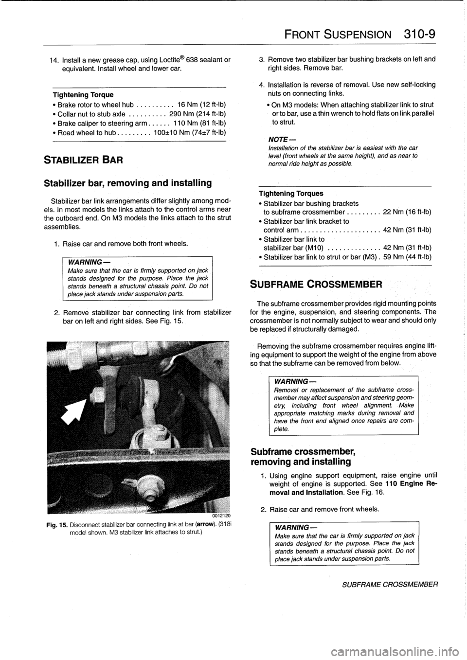
Fig
.
15
.
Disconnect
stabilizer
bar
connecting
link
at
bar
(arrow)
.
(3181
model
shown
.
M3
stabilizer
link
attaches
lo
strut
.)
FRONT
SUSPENSION
310-
9
14
.
Insta¡¡
a
new
grease
cap,
using
Loctite
©
638
sealant
or
3
.
Remove
two
stabilizer
bar
bushing
brackets
on
left
and
equivalent
.
Insta¡¡
wheel
and
lower
car
.
right
sides
.
Remove
bar
.
4
.
Installation
is
reverse
of
removal
.
Use
new
seif-lockíng
Tightening
Torque
núts
on
connecting
links
.
"
Brake
rotor
lo
wheel
hub
..........
16
Nm
(12
ft-Ib)
"
On
M3
models
:
When
attaching
stabilizer
link
lostrut
"
Collar
nut
lo
stubaxle
.
.........
290
Nm
(214
ft-Ib)
orlobar,
usea
thin
wrench
lo
hold
flats
on
link
parallel
"
Brake
caliper
losteering
arm
......
110
Nm
(81
ft-Ib)
lo
strut
.
"
Road
wheel
lo
hub
...
...
.
.
.
100±10
Nm
(74t7
ft-Ib)
NOTE-
Installation
of
the
stabilizer
bar
is
easiest
with
thecar
leve¡
(front
wheels
at
the
same
height),
and
as
near
to
normal
ride
height
as
possible
.
Tightening
Torques
"
Stabilizer
bar
bushing
brackets
lo
subframe
crossmember
...
..
.
..
.
22
Nm
(16
ft-Ib)
"
Stabilizer
bar
link
bracket
lo
control
arm
................
.
.
.
.
.
42
Nm
(31
ft-1b)
"
Stabilizer
bar
link
lo
stabilizer
bar
(M10)
.............
.
42
Nm
(31
ft-Ib)
"
Stabilizer
bar
link
lostrut
or
bar
(M3)
.
59
Nm
(44
ft-Ib)
SUBFRAME
CROSSMEMBER
The
subframe
crossmember
provides
rigid
mounting'poínts
2
.
Remove
stabilizer
bar
connecting
link
from
stabilizer
for
the
engine,
suspension,
and
steering
components
.
The
baron
left
and
right
sides
.
See
Fig
.
15
.
crossmember
is
not
normally
subject
lo
wear
and
should
ohly
be
replaced
if
structurally
damaged
.
Removing
the
subframe
crossmember
requires
engine
lift-
ing
equipment
lo
support
theweight
of
tfhe
engine
from
above
so
that
the
subframe
can
be
removed
from
below
.
WARNING-
Removal
or
replacement
of
the
subframe
cross-
member
may
affect
suspension
and
steering
geom-
etry,
including
front
wheel
afignment
.
Make
appropriate
matching
marks
during
removal
and
have
the
front
end
aligned
once
repairs
are
com-
plete
.
Subframe
crossmember,
removing
and
installing
1
.
Using
enginesupport
equipment,
raise
engine
until
weight
of
engine
is
supported
.
See
110EngineRe-
moval
and
Installation
.
See
Fig
.
16
.
2
.
Raise
car
andremove
front
wheels
.
WARNING-
Make
sure
that
the
car
is
firmly
supportedon
jack
stands
desígned
for
the
purpose
.
Place
the
jack
stands
beneatha
structural
chassís
point
Do
not
place
jack
standsundersuspension
parts
.
SUBFRAME
CROSSMEMBER
Page 266 of 759
310-
1
0
FRONT
SUSPENSION
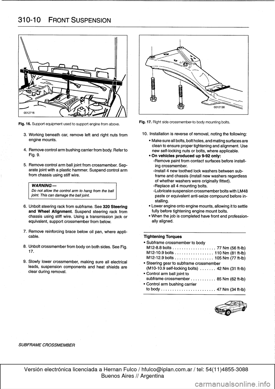
Fig
.
16
.
Supportequipment
used
to
support
engine
from
aboye
.
SUBFRAME
CROSSMEMBER
Fig
.
17
.
Right
side
crossmember-to
body
mounting
bolts
.
3
.
Working
beneath
car,
remove
left
and
right
nuts
from
10
.
Installation
is
reverse
ofremoval,
noting
the
followíng
:
engine
mounts
.
"
Make
sure
all
bolts,bolt
holes,
and
mating
surfaces
are
clean
to
ensure
proper
tightening
and
alignment
.
Use
4
.
Remove
control
arm
bushing
carrier
from
body
.
Refer
to
new
self-locking
nuts
or
bolts,
where
applicable
.
Fig
.
9
.
"
On
vehicles
produced
up
9-92
only
:
-Remove
paint
from
contact
surfaces
before
ínstall-
5
.
Remove
control
arm
ball
joint
from
crossmember
.
Sep-
ing
crossmember
.
arate
joint
with
a
plastic
hammer
.
Suspend
control
arm
-Install
4
new
toothed
lock
washersbetween
sub-from
chassis
using
stiff
wire
.
frame
and
chassis
(install
new
washers
regardless
of
whether
washers
were
originally
fitted)
.
WARNING-
-Replace
all
4
mounting
bolts
.
Do
not
allow
the
control
arm
to
hang
from
the
ball
-Lubrícate
suspension
crossmember
bolts
with
LM48
¡oint
.
This
can
damage
theball¡oint
.
paste
orequivalent
anti-seize
compound
before
ín-
stalling
.
6
.
Unbolt
steering
rack
from
subframe
.
See
320
Steering
"
Lower
engine
onto
enginemounts,
allowing
it
to
settle
and
Wheel
Alignment
.
Suspend
steering
rack
from
fully
before
tightening
engine
mount
bolts
.
chassis
using
stiff
wire
.
Using
a
transmission
jackor
"
When
thejob
is
completed
have
front
end
profession-
equivalent,
support
crossmember
from
below
.
ally
aligned
.
7
.
Remove
reinforcing
brace
below
oil
pan,
where
appli-
cable
.
Tightening
Torques
"
Subframe
crossmember
to
body
8
.
Unbolt
crossmemberfrom
body
on
both
sides
.
See
Fig
.
M12-8
.8
bolts
..................
.
77
Nm
(56
ft-Ib)
17
.
M12-10
.9
bolts
.................
110
Nm
(81
ft-Ib)
M12-12
.9
bolts
............
.
...
.
105
Nm
(77
ft-Ib)
9
.
Slowly
Lower
crossmember,
making
sure
all
electrical
"
Steering
gear
to
subframe
crossmember
teads,
suspension
components
and
heat
shields
are
(M10-10
.9
self-locking
bolts)
..
.
.
.
.
.
42
Nm
(31
ft-Ib)
clear
during
removal
.
"
Control
arm
balljoint
to
subframe
crossmember
...
.......
.
85
Nm
(62
ft-Ib)
"
Control
arm
bushing
carrier
to
body
..........
...
.
.....
.
..
..
47
Nm
(34
ft-Ib)