door wiring BMW 318i 1992 E36 Workshop Manual
[x] Cancel search | Manufacturer: BMW, Model Year: 1992, Model line: 318i, Model: BMW 318i 1992 E36Pages: 759
Page 3 of 759
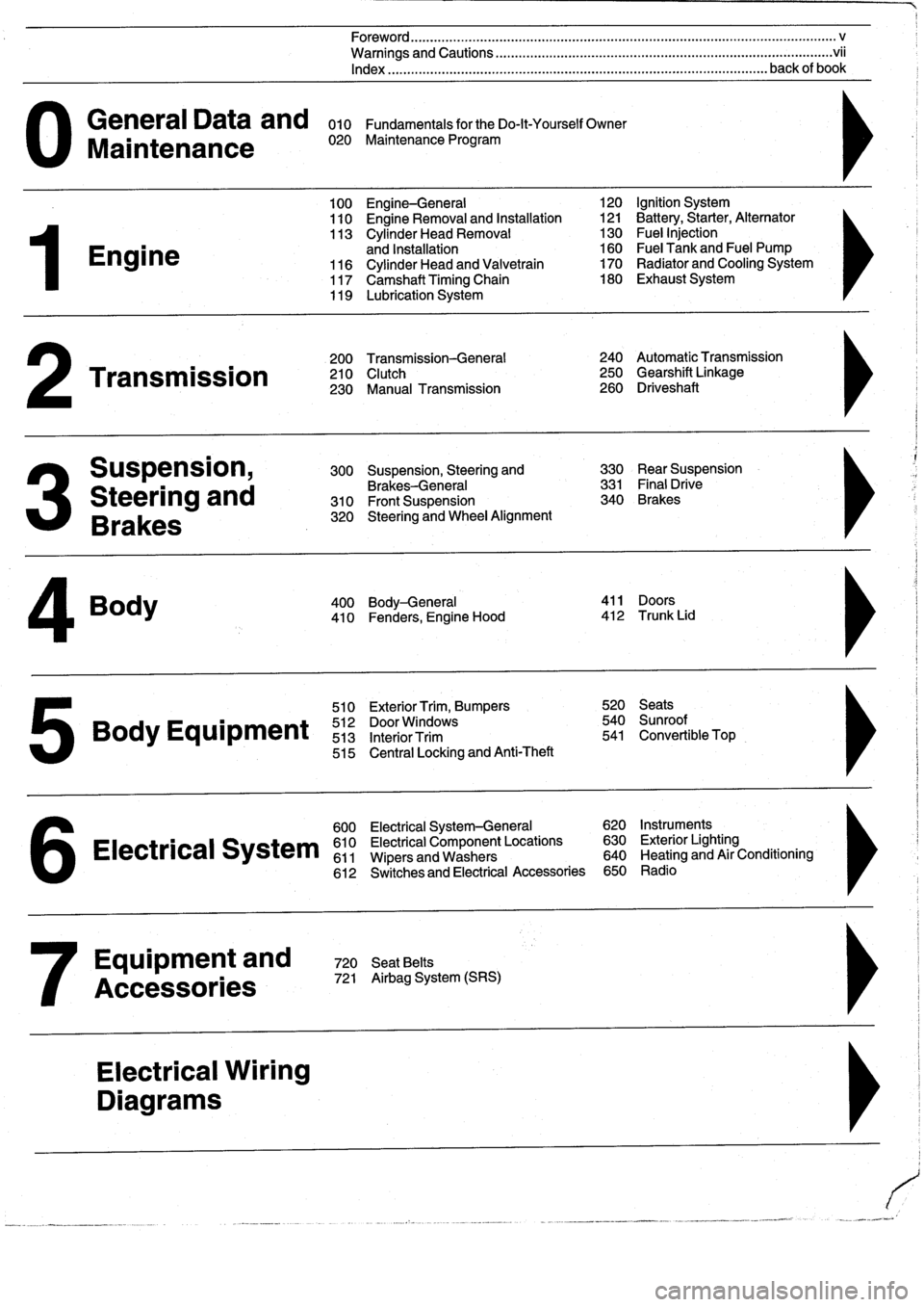
General
Data
and
010
FundamentalsfortheDo-lt-YourselfOwner
Maintenance
020
Maintenance
Program
Engine
Transmission
Suspension,
Steering
and
Brakes
4
Body
100
Engine-General
110
Engine
Removal
and
Installation
113
Cylinder
Head
Removal
and
Installation
116
Cylinder
Head
and
Valvetrain
117
Camshaft
Timing
Chain
119
Lubrication
System
200
Transmission-General
210
Clutch
230
Manual
Transmission
510
Exterior
Trim,
Bumpers
520
Seats
Bo
y
Equipment
512
DoorWTdws
540
nr
t
513
InteriorTrim
541
Convertible
Top
515
Central
Locking
and
Anti-Theft
600
Electrical
System-General
620
Instruments
Electrical
S
stem
610
Electrical
Component
Locations
630
Exterior
Lighting
611
Wipers
and
Washers
640
Heating
and
Air
Conditioning
6
612
Switches
and
Electrical
Accessories
650
Radio
Equipment
and
720
SeatBelts
Accessories
721
Airbag
System
(SRS)
Electrical
Wiring
Diagrams
Foreword
.
...
.
.
.
..................
.
.
.
.....
.
............
.
...
.
.
.
.
.
................
.
.
.
.....
.
......
.
................
.
.
.
.....
v
Warnings
and
Cautions
.....
.
...
.
.
.
.
.
..........
.
...
.
.
.
.
.
......
.
.........
.
.
.
...
.
.
.
......
.
.
.
.
.
............
.
.
.
.
.
.
.vii
Index
..............
.
.
.
.....
.
............
.
...
.
.
.
.
.
........
.
...
.
.
.
.
.
.......
.
......
.
...
.
.
.
.
.
.
.
........
.
.
.
..
back
of
book
300
Suspension,
Steering
and
330
RearSuspension
Brakes-General
331
Final
Drive
310
Front
Suspension
340
Brakes
320
Steering
and
Wheel
Alignment
400
Body-General
411
Doors
410
Fenders,
Engine
Hood
412
Trunk
Lid
120
Ignition
System
121
Battery,Starter,
Alternator
130
Fue¡
Injection
160
Fuel
Tank
and
Fuel
Pump
170
Radiator
and
Cooling
System180
Exhaust
System
240
Automatic
Transmission
250
Gearshift
Linkage
260
Driveshaft
Page 160 of 759
130-
1
4
FUEL
INJECTION
NOTE-
Be
sure
to
retrieve
thrust
washer
behind
fuel
pressure
regulator
on
6-cylinder
engine
.
4
.
Installation
is
reverse
of
removal
.
Replace
O-rings
.
Fuel
pressure
regulator,
replacing
(under
car
mount)
WARNING
-
Fuel
will
be
discharged
.
Do
not
disconnect
any
wires
that
could
cause
electrical
sparks
.
Do
not
smoke
or
work
near
heaters
or
other
fire
hazards
.
Keep
an
approved
tire
extinguisher
handy
.
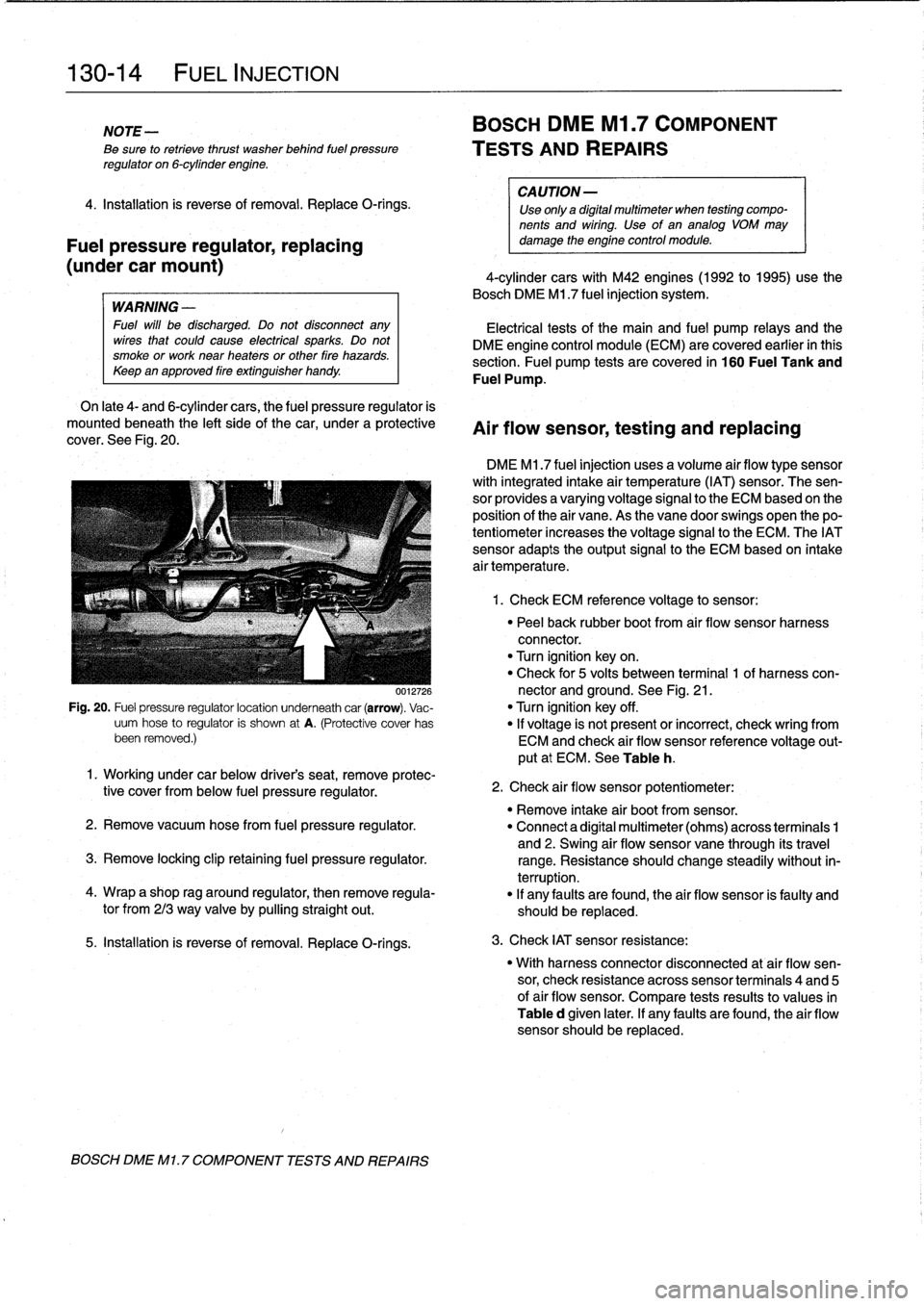
On
late
4-
and
6-cylinder
cars,
the
fuel
pressure
regulator
is
mounted
beneath
the
left
sideof
the
car,
under
a
protective
cover
.
See
Fig
.
20
.
0012726
Fig
.
20
.
Fuel
pressure
regulatorlocation
underneath
car
(arrow)
.
Vac-
uum
hose
to
regulator
is
shown
at
A
.
(Protective
cover
has
been
removed
.)
5
.
Installation
is
reverse
of
removal
.
Replace
O-rings
.
BOSCH
DME
Ml
.
7
COMPONENT
TESTS
AND
REPAIRS
BOSCH
DME
Ml
.7
COMPONENT
TESTS
AND
REPAIRS
CA
UTION-
Use
only
a
digital
multimeter
when
testing
compo-
nents
and
wiring
.
Use
of
an
analog
VOM
may
damage
the
engine
control
module
.
4-cylinder
cars
with
M42
engines(1992
to
1995)use
the
Bosch
DME
M1
.7
fuel
injection
system
.
Electrical
tests
of
the
main
and
fuel
pump
relays
and
the
DME
engine
control
module
(ECM)
are
covered
earlier
in
this
section
.
Fuel
pump
tests
arecovered
in
160
Fuel
Tank
and
Fuel
Pump
.
Air
flow
sensor,
testing
and
replacing
DME
M1
.7
fuel
injection
uses
a
volume
air
flow
type
sensor
with
integrated
intake
air
temperature
(IAT)
sensor
.
The
sen-
sor
provides
a
varyingvoltage
signal
to
the
ECM
based
on
the
position
of
the
air
vane
.
As
the
vane
doorswings
open
thepo-
tentiometer
increases
the
voltage
signal
to
the
ECM
.
The
IATsensor
adapts
theoutput
signal
to
the
ECM
based
on
intake
air
temperature
.
1
.
Check
ECM
reference
voltage
to
sensor
:
"
Peel
back
rubber
boot
from
air
flow
sensor
harness
connector
.
"
Turn
ignition
keyon
.
"
Check
for
5
volts
between
terminal
1
of
harness
con-
nector
and
ground
.
See
Fig
.
21
.
"
Turn
ignition
key
off
.
"
If
voltage
is
not
present
or
incorrect,
check
wring
from
ECM
and
check
air
flow
sensor
reference
voltage
out-
put
at
ECM
.
See
Table
h
.
1
.
Working
under
car
below
driver's
seat,
remove
protec-
tive
cover
from
below
fuel
pressure
regulator
.
"
Remove
intake
air
bootfrom
sensor
.
2
.
Remove
vacuum
hosefrom
fuel
pressure
regulator
.
"
Connect
a
digital
multimeter
(ohms)
across
terminais
1
and
2
.
Swing
air
flow
sensor
vane
through
its
travel
3
.
Remove
locking
clip
retaining
fuel
pressure
regulator
.
range
.
Resistance
should
change
steadily
without
in-
terruption
.
4
.
Wrap
a
shop
rag
around
regulator,
then
remove
regula-
"
If
any
faults
are
found,
the
air
flow
sensor
is
faulty
and
tor
from
213
way
valve
by
pullingstraight
out
.
should
be
replaced
.
2
.
Check
air
flow
sensor
potentiometer
:
3
.
Check
IAT
sensor
resistance
:
"
With
harness
connector
disconnected
at
air
flow
sen-
sor,
check
resistance
across
sensor
terminais
4
and
5
of
air
flow
sensor
.
Compare
tests
results
to
values
in
Table
d
given
later
.
If
any
faults
are
found,
the
air
flow
sensor
should
be
replaced
.
Page 316 of 759
411-2
DOORS
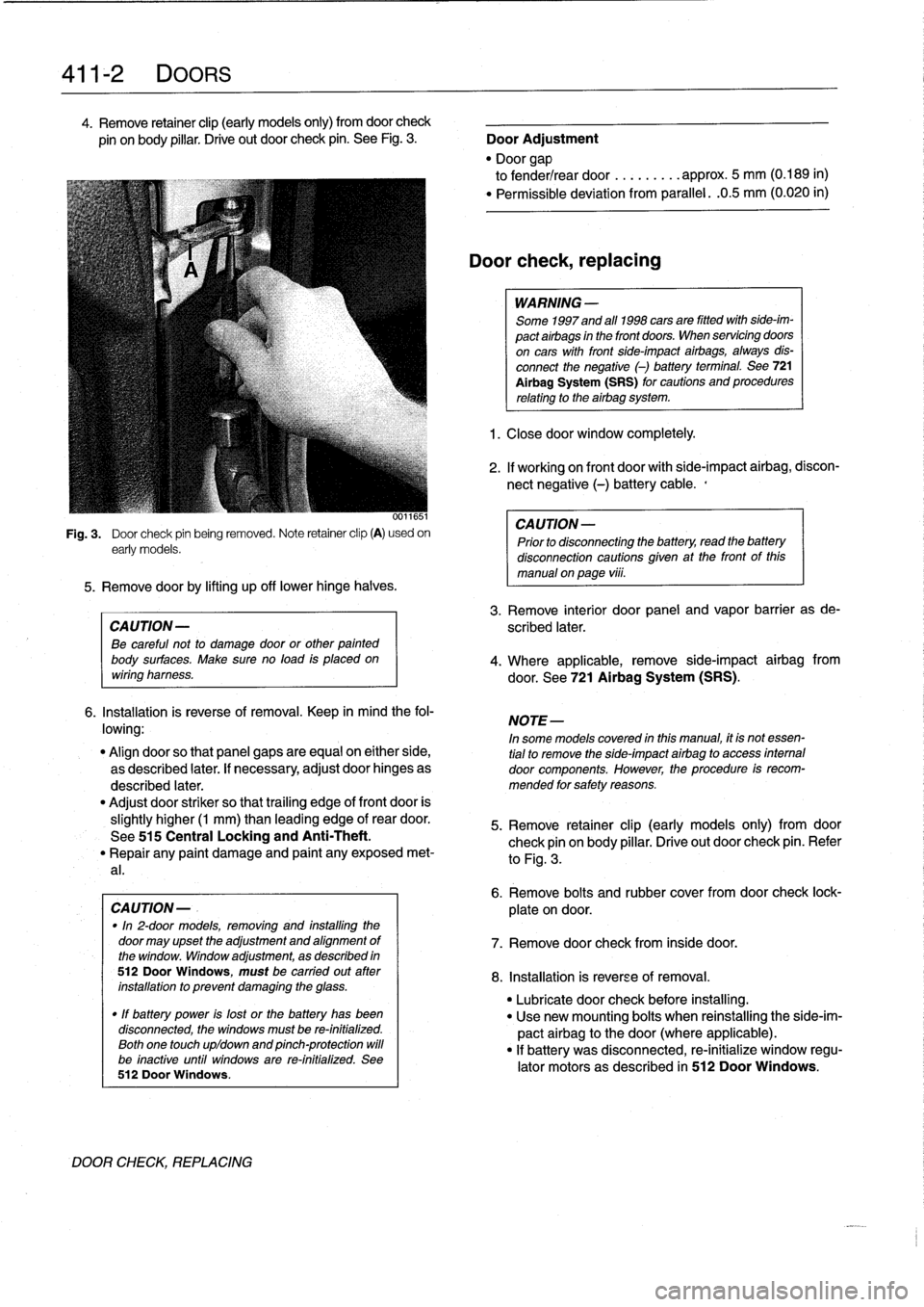
4
.
Remove
retainer
clip
(early
models
only)
from
doorcheck
pin
onbody
pillar
.
Drive
out
door
check
pin
.
See
Fig
.
3
.
Door
Adjustment
"
Door
gap
to
fender/rear
door
.........
approx
.
5
mm
(0
.189
in)
"
Permíssible
deviation
from
parallel
.
.0
.5
mm
(0
.020
in)
0011651
Fig
.
3
.
Door
check
pin
being
removed
.
Note
retainer
clip
(A)
usedon
early
models
.
5
.
Remove
doorby
lifting
up
off
lowerhinge
halves
.
CAUTION-
Be
careful
not
to
damage
door
or
other
painted
body
surfaces
.
Make
sure
no
load
is
placedon
wiring
harness
.
6
.
Installation
is
reverse
of
removal
.
Keep
in
mind
the
fol-
lowing
:
"
Align
doorso
that
panel
gaps
are
equal
on
either
side,
as
described
later
.
If
necessary,
adjust
door
hinges
as
described
later
.
"
Adjust
door
striker
so
that
trailing
edge
of
front
door
is
slightly
higher
(1
mm)
than
leading
edge
of
rear
door
.
See
515
Central
Locking
and
Anti-Theft
.
"
Repair
any
paint
damage
and
paínt
any
exposed
met-
al
.
CAUTION-
.
"In
2-door
models,
removing
and
installing
the
door
may
upset
the
adjustment
and
alignment
of
the
window
.
Window
adjustment,
as
described
in
512DoorWindows,
must
be
carried
out
ater
installation
to
prevent
damaging
the
glass
.
"
If
battery
power
is
lost
or
the
battery
has
been
disconnected,
the
windows
must
be
re-initialized
.
Both
one
touch
upldown
and
pinch-protection
will
be
inactive
until
windows
are
re-initialized
.
See
512
Door
Windows
.
DOOR
CHECK,
REPLACING
Door
check,replacing
WARNING
-
Some
1997
and
all
1998
cars
are
fitted
with
side-im-
pact
airbags
in
the
front
doors
.
When
servicing
doors
on
cars
with
front
side-impact
airbags,
always
dis-
connect
the
negative
(-)
battery
terminal
.
See
721
Al
rbag
System
(SRS)
for
cautions
and
procedures
relating
to
the
airbag
system
.
1
.
Closedoor
window
completely
.
2
.
If
working
on
front
door
with
side-impact
airbag,
discon-
nect
negative
(-)
battery
cable
.,
CAUTION-
Prior
to
disconnectiog
the
battery,
read
the
battery
disconnection
cautions
gíven
at
the
front
of
this
manual
on
page
viii
.
3
.
Remove
interior
door
panel
and
vapor
barrier
as
de-
scribed
later
.
4
.
Where
applicable,
remove
side-impact
airbag
from
door
.
See
721
Airbag
System
(SRS)
.
NOTE-
In
some
models
covered
inthis
manual,
ít
is
not
essen-
tial
to
remove
the
side-ímpact
airbag
to
access
internal
door
components
.
However,
the
procedure
is
recom-
mended
for
safety
reasons
.
5
.
Remove
retainer
clip
(early
models
only)
from
door
check
pin
on
body
pillar
.
Drive
out
door
check
pin
.
Refer
to
Fig
.
3
.
6
.
Remove
bolts
and
rubber
cover
fromdoor
check
lock-
plate
ondoor
.
7
.
Remove
door
check
from
inside
door
.
8
.
Installation
is
reverse
of
removal
.
"
Lubricate
door
check
before
installing
.
"
Use
new
mounting
bolts
when
reinstalling
the
side-im-
pact
airbag
to
thedoor(where
applicable)
.
"
If
battery
was
disconnected,
re-initialize
window
regu-
lator
motors
as
described
in
512
Door
Windows
.
Page 342 of 759
512-
1
2
DOOR
WINDOWS
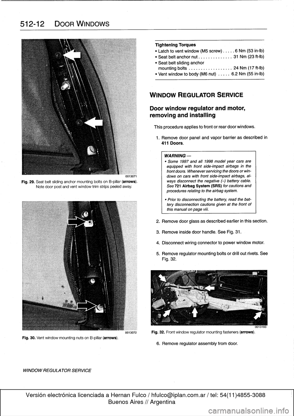
Fig
.
30
.
Vent
window
mounting
nuts
on
B-pillar
(arrows)
.
WINDOW
REGULATOR
SERVICE
0013071
Fig
.
29
.
Seat
belt
sliding
anchor
mounting
bolts
on
B-pillar
(arrows)
.
Notedoor
post
and
vent
window
trim
strips
peeled
away
.
Tightening
Torques
"
Latch
to
vent
window
(M5
screw)
.....
6
Nm
(53
in-lb)
"
Seat
belt
anchor
nut
..............
31
Nm
(23
ft-Ib)
"
Seat
belt
sliding
anchor
mounting
bolts
.
..
...
.
...........
24
Nm
(17
ft-Ib)
"
Vent
window
to
body(M6
nut)
.....
6
.2
Nm
(55
in-lb)
WINDOW
REGULATOR
SERVICE
Door
window
regulator
and
motor,
removing
and
installing
This
procedure
applies
to
front
or
rear
door
windows
.
1
.
Remove
door
panel
and
vapor
barrier
as
described
in
411
Doors
.
WARNING
-
"
Some
1997
and
all
1998
model
year
cars
are
equipped
with
front
side-impact
airbags
in
the
front
doors
.
Whenever
servicing
the
doors
orwin-
dows
on
cars
with
front
side-impact
airbags,
al-
ways
disconnect
the
negative
(-)
battery
cable
.
See
721
Airbag
System
(SRS)
for
cautions
and
procedures
relating
to
the
airbag
system
.
"
Prior
to
disconnectiog
the
battery,
read
the
bat-tery
disconnection
cautions
gíven
at
the
front
of
this
manual
onpage
vi¡¡
.
2
.
Remove
door
glass
as
described
earlier
in
this
section
.
3
.
Remove
inside
door
handle
.
See
Fig
.
31
.
4
.
Disconnect
wiring
connector
to
power
window
motor
.
5
.
Remove
regulator
mounting
bolts
or
drill
out
rivets
.
See
Fig
.
32
.
0013193
0013072
Fig
.
32
.
Front
window
regulator
mounting
fasteners
(arrows)
.
6
.
Remove
regulator
assembly
fromdoor
.
Page 349 of 759
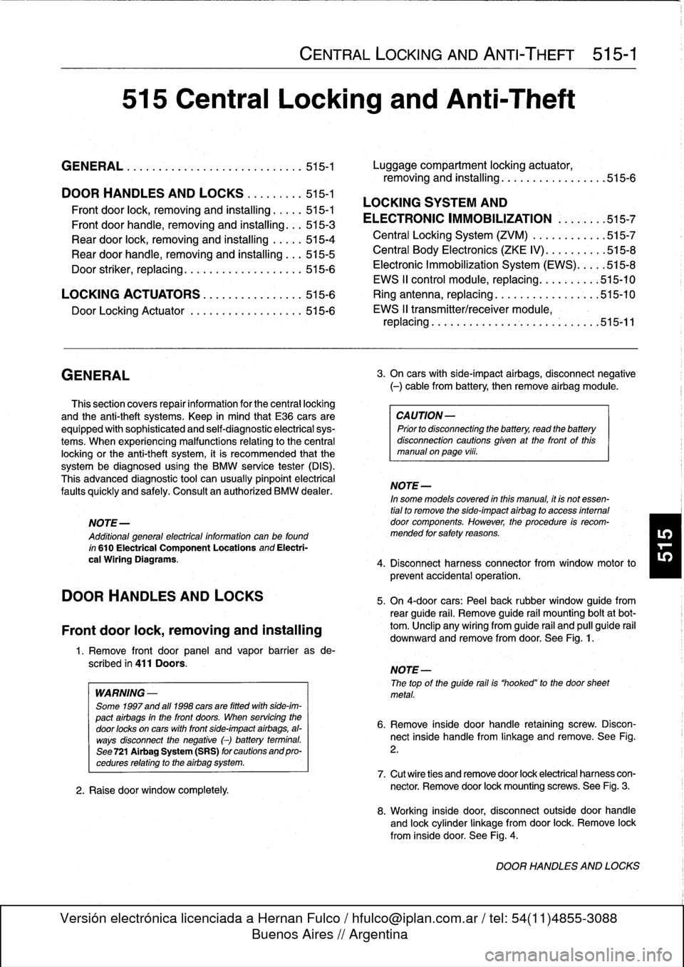
515
Central
Locking
and
Anti-Theft
GENERAL
.....
.
.
.
.
.
.
.
..:
.
.
.
......
.
.
.
.
515-1
Luggage
compartment
locking
actuator,
removing
and
installing
.
.
.
.
.
...........
.
515-6
DOOR
HANDLES
AND
LOCKS
.........
515-1
LOCKING
SYSTEM
AND
Front
door
lock,
removing
and
installing
....
.515-1
ELECTRONIC
IMMOBILIZATION
......
.515-7
Front
door
handle,
removing
and
installing
...
515-3
Rear
door
lock,
removing
and
installing
.....
515-4
Central
Locking
System(ZVM)
.
.
.
.
.......
.
515-7
Rear
door
handle,
removing
and
installing
...
515-5
Central
Body
Electronics
(ZKE
IV)
.
.
.......
.515-8
Electronic
Immobilization
System
(EWS)
.
.
.
.
.515-8
Door
striker,
rep
lacing
.
.
.
.
.
.
.
.
.
..........
515-6
EWS
II
control
module,
re
lacin
515-10
LOCKING
ACTUATORS
.
.
.
.
.
.
..........
515-6
Ring
antenna,
replacing
.
.
.
.
.
.
.
.
.
.
...
.
.
.
.
515-10
Door
Locking
Actuator
.
.
.
.
.
.
.
.
..........
515-6
EWS
II
transmitter/receiver
module,
replacing
...........
.
.
.
.
.
.
.
.
.
.
.
.
.
.
.
.
515-11
GENERAL
This
section
covers
repair
information
for
the
central
locking
and
the
anti-theft
systems
.
Keep
in
mind
that
E36
cars
are
CA
UTION-
equipped
with
sophisticated
and
self-diagnostic
electrical
sys-
Prior
to
disconnecting
the
battery,
read
the
battery
tems
.
When
experiencing
malfunctions
relatinglo
the
central
disconnection
cautions
given
at
the
front
of
this
locking
or
the
anti-theft
system,
it
is
recommended
that
the
manual
onpage
vi¡¡
.
systembe
diagnosed
using
the
BMW
service
tester
(DIS)
.
This
advanced
diagnostic
tool
can
usually
pinpoint
electrical
NOTE-
faults
quickly
and
safely
.
Consult
an
authorized
BMW
dealer
.
In
some
models
covered
inthis
manual,
it
is
not
essen-
tial
to
remove
the
side-impact
airbag
to
access
intemal
NOTE-
door
components
.
However,
the
procedure
is
recom-
Additional
general
electrical
information
can
be
found
mended
for
safely
reasons
.
i
n
610
Electrical
Component
Locations
and
Electri-
cal
Wiring
Diagrams
.
4
.
Disconnect
harnessconnector
from
window
motor
to
DOOR
HANDLES
AND
LOCKS
Front
door
lock,
removing
and
installing
1
.
Remove
front
door
panel
and
vapor
barrier
asde-
scribed
in
411
Doors
.
WARNING
-
Some
1997
and
all
1998
cars
are
fitted
with
side-im-
pact
airbags
in
the
front
doors
.
When
servicing
the
door
locks
on
cars
with
front
side-impact
airbags,
al-
ways
disconnect
the
negative
(-)
battery
terminal
.
See721
Airbag
System
(SRS)
forcautions
andpro-
cedures
relating
to
the
airbag
system
.
2
.
Raise
door
window
completely
CENTRAL
LOCKING
AND
ANTI-THEFT
515-1
3
.
On
cars
with
side-impact
airbags,
disconnect
negative
(-)
cable
from
battery,
then
remove
airbag
module
.
prevent
accidental
operation
.
5
.
On
4-door
cars
:
Peel
back
rubber
window
guide
from
reas
guide
rail
:
Remove
guide
rail
mounting
boltat
bot-
tom
.
Unclip
any
wiring
from
guide
rail
and
pull
guide
rail
downward
and
remove
from
door
.
See
Fig
.
1
.
NOTE
-
The
top
of
the
guide
rail
is
"hooked"
to
the
doorsheet
metal
.
6
.
Remove
inside
door
handle
retaining
screw
.
Discon-
nect
inside
handle
from
linkage
and
remove
.
See
Fig
.
2
.
7
.
Cut
wire
ties
and
remove
door
lock
electrical
harness
con-
nector
.
Remove
door
lock
mounting
screws
.
See
Fig
.
3
.
8
.
Working
inside
door,
disconnect
outside
door
handle
and
lockcylinder
linkage
from
door
lock
.
Remove
lock
from
inside
door
.
See
Fig
.
4
.
DOOR
HANDLES
AND
LOCKS
Page 354 of 759
515-6
CENTRAL
LOCKING
AND
ANTI-THEFT
6
.
Remove
door
handle
assembly
from
inside
door
.
7
.
Installation
is
reverse
of
removal
.
Keep
in
mindthe
fol-
lowing
:
"
Make
sure
rubber
seal
for
handle
is
correctly
posi-
tionedbefore
tightening
mounting
fasteners
.
"
Install
exterior
trim
piece
and
then
use
a
hooked
toolto
pull
locking
plate
into
locked
position
.
Make
sure
door
handle
trim
contacts
body
evenly
before
lockingtrim
in
place
.
"
Reconnect
all
harness
connectors
(including
power
window
motor)before
installing
door
panel
.
"
Secure
wire
harnesses
withwire
ties
.
"
Adjust
windowas
described
in
512
Door
Windows
.
Tightening
Torque
"
Rear
door
handle
mounting
screws
..
10
Nm
(89
in-lb)
NOTE
If
the
striker
backup
plate
fafls
into
the
body
cavlty,
it
can
be
retrieved
after
removing
the
inside
trim
from
the
B-pillar
(door-post
pillar)
.
Tightening
Torque
"
Striker
plate
to
body
pillar
..........
28
Nm
(20
ft-lb)
LOCKING
ACTUATORS
Door
Locking
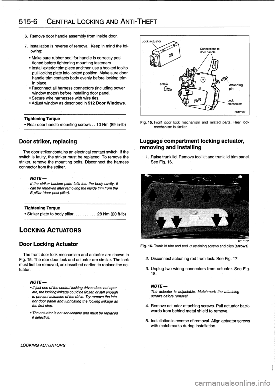
Actuator
The
front
door
lock
mechanism
and
actuator
are
shown
in
Fig
.
15
.
The
rear
door
lock
and
actuator
are
similar
.
The
lock
must
first
be
removed,
as
described
earlier,
to
replace
the
ac-
tuator
.
if
defective
.
LOCKING
ACTUATORS
Connections
to
door
handle
®
o
_
Attaching
pin
0
O~
Lock
mechanism
0012082
Fig
.
15
.
Front
door
lock
mechanism
and
related
parts
.
Rear
lock
mechanism
is
similar
.
Door
striker,
replacing
Luggage
compartment
locking
actuator,
removing
and
installing
The
door
striker
contains
an
electrical
contact
switch
.
If
the
switch
is
faulty,
the
striker
must
be
replaced
.
To
remove
the
1
.
Raise
trunk
lid
.
Remove
tool
kit
and
trunk
lid
trim
panel
.
striker,
remove
the
mounting
bolts
.
Disconnect
the
harness
See
Fig
.
16
.
connector
from
the
striker
.
0013162
Fig
.
16
.
Trunk
lid
trim
and
tool
kit
retainíng
screws
and
clips
(arrows)
.
2
.
Disconnect
actuating
rod
from
lock
.
See
Fig
.
17
.
3
.
lJnplug
two
wíring
connectors
from
actuator
.
See
Fig
.
18
.
NOTE
-
"
lf
just
one
of
the
centrallocking
drives
does
not
oper-
NOTE-
ate,
the
lockinglinkage
could
be
frozen
orstiff
enough
The
actuator
is
adjustable
.
Matchmark
the
attaching
to
prevent
actuatonof
the
drive
.
Try
remove
the
finte-
screws
before
removal
.
rior
doorpanel
and
lubricating
the
locking
linkage
as
the
first
step
.
4
.
Remove
actuator
attaching
screws
.
Pull
actuator
back-
"
The
actuator
is
not
serviceable
and
mustbe
replaced
wards
from
behind
metal
shield
to
remove
.
5
.
installation
is
reverse
of
removal
.
Align
actuator
screws
with
matchmarks
during
installation
.
Page 362 of 759
520-2
S
EATS
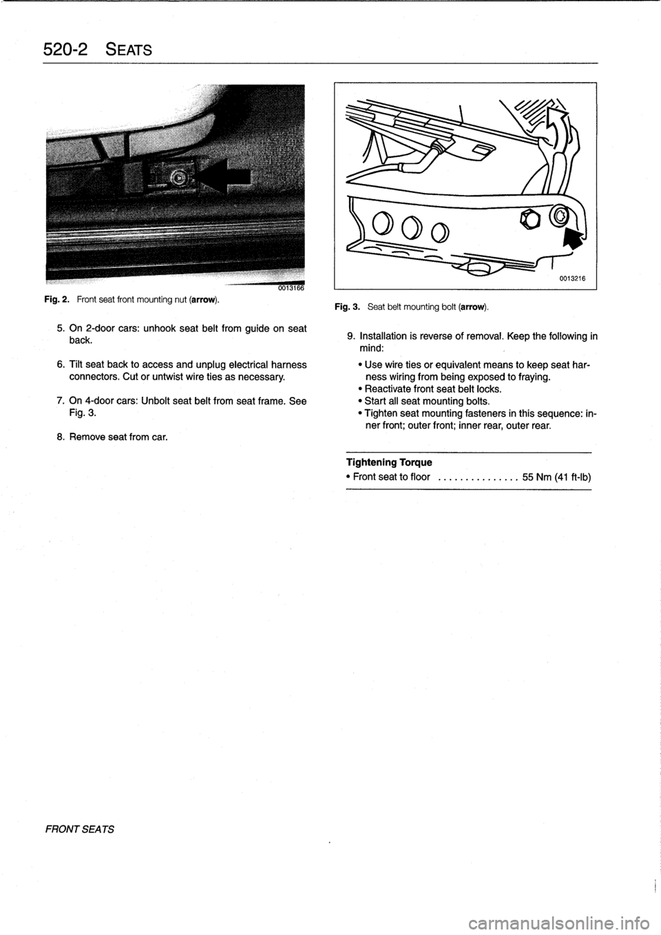
Fig
.
2
.
Frontseat
front
mounting
nut
(arrow)
.
FRONT
SEA
TS
0013166
5
.
On
2-door
cars
:
unhook
seat
belt
from
guide
on
seat
back
.
8
.
Remove
seatfrom
car
.
Fig
.
3
.
Seat
belt
mounting
bolt
(arrow)
.
0013216
9
.
Installation
is
reverse
of
removal
.
Keep
the
following
in
mind
:
6
.
Tilt
seat
back
to
access
and
unplug
electrical
harness
"
Use
wire
ties
orequivalent
means
to
keep
seat
har
connectors
.
Cut
or
untwist
wire
ties
as
necessary
.
ness
wiring
from
being
exposed
to
fraying
.
"
Reactivate
front
seat
belt
locks
.
7
.
On
4-door
cars
:
Unbolt
seat
belt
from
seat
frame
.
See
"
Start
all
seat
mounting
boits
.
Fig
.
3
.
"
Tighten
seat
mounting
fasteners
in
thís
sequence
:
in-
ner
front
;
outer
front
;
inner
rear,
outer
rear
.
Tightening
Torque
"
Front
seat
to
floor
........
.......
55
Nm
(41
ft-Ib)
Page 364 of 759
520-
4
SEATS
Power
Front
Seat
Assembly
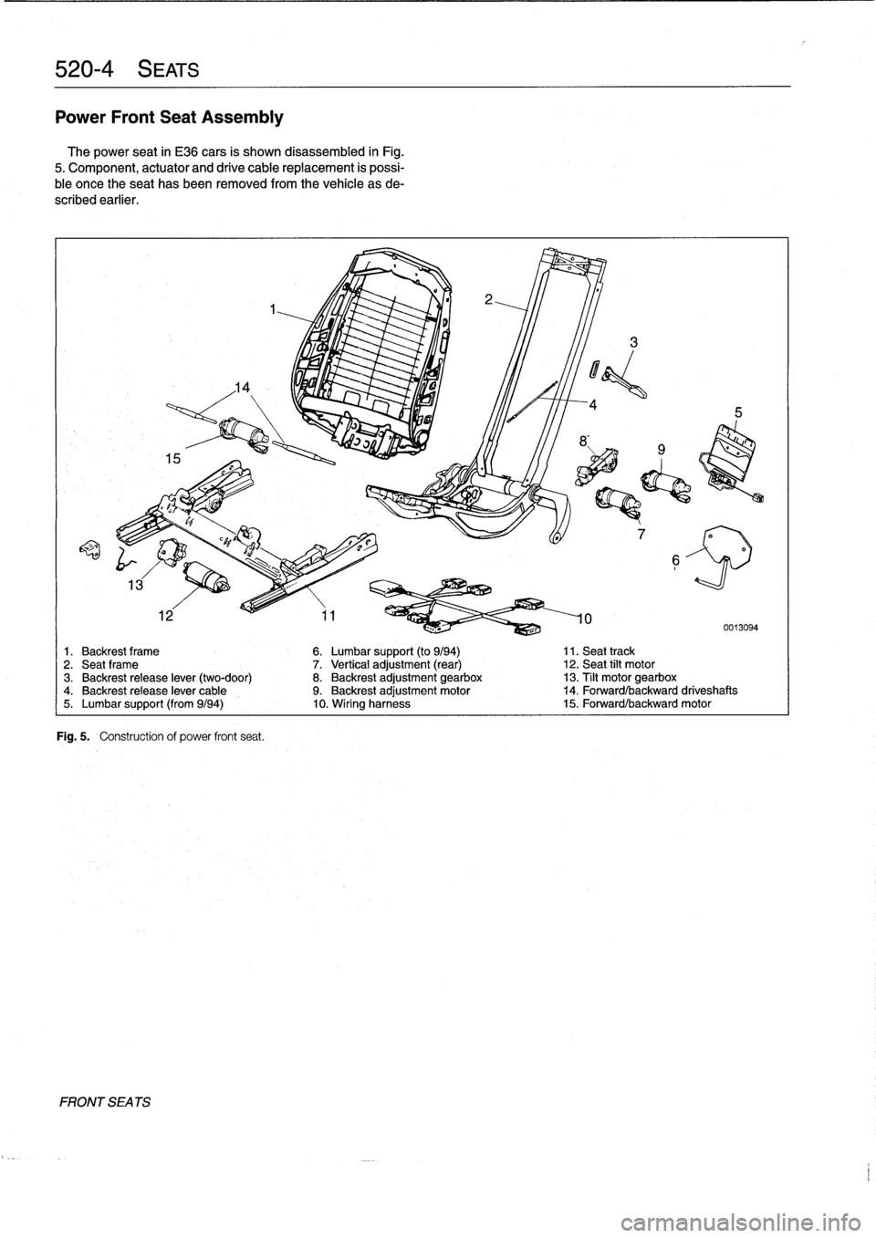
The
power
seat
in
E36
cars
is
shown
disassembled
in
Fig
.
5
.
Component,
actuator
and
drive
cable
replacement
is
possi-
ble
once
theseat
has
been
removed
from
the
vehicle
as
de-
scribed
earlier
.
FRONT
SEA
TS
Fig
.
5
.
Construction
of
power
front
seat
.
1
.
Backrest
frame
6
.
Lumbar
support
(to
9/94)
11
.
Seat
track
2
.
Seatframe
7
.
Vertical
adjustment
(rear)
12
.
Seat
tilt
motor3
.
Backrest
release
lever
(two-door)
8
.
Backrest
adjustment
gearbox
13
.
Tilt
motorgearbox4
.
Backrest
release
lever
cable
9
.
Backrest
adjustment
motor
14
.
Forward/backward
driveshafts
5
.
Lumbar
support
(from9/94)
10
.
Wiring
harness
15
.
Forward/backwardmotor
Page 419 of 759
611
Wipers
and
Washers
GENERAL
..
.
.
.
.
.
.
.
.
.
.
.
.
.
.....
.
......
.
611-1
Windshield
wiper
motor,
removing
and
installing
.
...............
.611-8
WIPER
BLADES
.
.
.
.....
.
.
.
.
.
.
...
....
.611-1
Wiper
Blade
Cleaning
Problems
.
.
.
.
.
.
.....
611-1
Wiper
blades,replacing
...
.
.
.
.
.
.
.
.
.
.....
611-1
Wiper
blade
inserts,
replacing
.
.
.
.
.
.
.
.
.....
611-2
Wiper
arms,
removing
and
installing
.
.
.
.....
611-2
WINDSHIELD
WIPER
ASSEMBLY
.
.
.....
611-3
Windshield
wiper
assembly,
removing
and
installing
(4-door
models)
.
.
.
.
.
.
.....
611-3
Windshield
wiper
assembly,
removing
and
installing
(2-door
models)
.
.
.
.
.
.
.....
611-5
GENERAL
This
repair
group
covers
windshield
wiper
and
washer
sys-
tem
repair
information
.
Please
note
that
some
procedures
are
different
for
2-
and
4-door
models
.
The
windshield
wiper/washer
stalk
switch
assembly
is
cov-
ered
in
612
Switches
and
Electrical
Accessories
.
Electrical
NOTE-
wiring
diagrams
and
relays
for
the
wiper/washer
system
are
BMwhas
available
a
special
toollgauge
(BMWspecial
covered
in
Electrical
Wiring
Diagrams
.
tool
no
.
00
9210)
to
align
the
angle
of
the
wiper
arm
to
the
windshield
glass
.
WIPERBLADES
CA
UTION-
Never
turn
on
the
wiper
blades
while
the
hood
is
open
.
Damage
to
the
wiper
system
and
hood
may
occur
.
Toensure
safetyduring
wiper
biade
system
procedures,
remove
the
windshieldwiper
fuse
.
See
610
Electrical
Component
Locations
.
Wiper
Blade
Cleaning
Problems
Common
cleaning
problems
with
thewipers
includestreak-
ing
or
sheeting,
waterdrops
after
wiping,
and
blade
chatter
.
Streaking
is
usually
caused
when
wiper
blades
are
coated
with
road
film
or
car
wash
wax
.
Clean
the
blades
using
soapy
water
.
If
cleaning
does
not
cure
the
problem,
the
blades
should
be
replaced
.
BMW
recommends
replacing
the
wiper
blades
twice
a
year,
before
and
after
the
cold
season
.
WIPERS
AND
WASHERS
611-1
WINDSHIELD
CLEANING
SYSTEM
......
611-9
Windshield
spray
nozzle,
removing
and
installing
.......
.
........
.611-9
Washer
fluid
reservoir,
replacing
.........
.611-9
Windshield
washer
fluid
pump,
replacing
..
.
......
.
........
.611-9
Washer
fluid
level
sensor,
replacing
(models
with
check
control)
.
.
.
.
........
611-10
Wiper
blade
chatter
may
be
caused
by
dirty
or
worn
blades,
or
by
wiper
arms
that
areout
of
alignment
.
Clean
the
blades
and
windshield
as
described
above
.
Adjust
the
wiper
arm
so
that
there
is
even
pressure
along
the
blade,
and
so
that
the
blade
at
rest
is
perpendicular
to
the
windshield
.
If
problems
persist,
theblades
and
wiper
arms
should
be
replaced
.
The
wiper
blades
can
be
renewed
in
one
of
two
ways
:
either
by
replacing
the
complete
blade
or
by
replacing
just
therubber
insert
.
Insert
replacement
is
the
mosteconomicalmethod,
al-
though
overtime
the
wiperblade
itselfwill
become
worn
.
One
ruleof
thumb
wouldbe
to
replace
just
the
inserts
every
second
time
.
Wiper
blades,
replacing
1
.
Pivot
wiper
arm
off
windshield
.
2
.
Position
wiperblade
approximately
perpendicular
to
wiper
arm
.
3
.
Remove
wiperblade
from
wiper
arm
by
depressing
re-
taining
tab
and
sliding
blade
out
of
arm
.
See
Fig
.
1
.
Drops
that
remain
behind
after
wiping
are
usually
caused
by
NOTE-
oil,
road
film,
or
diesel
exhaust
residue
onthe
glass
.
Use
an
Some
wiperblade
versions
may
havetwo
retaining
alcohol
or
ammonia
solution
or
a
non-abrasive
cleaner
(such
tabs
.
a
s
Bon-Ami
to
clean
the
windshield
.
GENERAL
Page 423 of 759
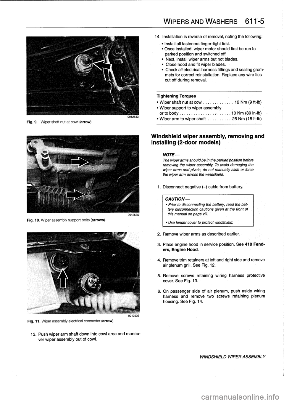
Fig
.
9
.
Wiper
shaft
nut
at
cowl
(arrow)
.
Fig
.
10
.
Wiper
assembly
support
bolts
(arrows)
.
0012533
0012535
Fig
.
11
.
Wiper
assembly
electrical
connector
(arrow)
.
0012536
13
.
Push
wiper
arm
shaft
down
into
cowl
area
and
maneu-
ver
wiper
assembly
out
of
cowl
.
WIPERS
AND
WASHERS
611-
5
14
.
Installation
is
reverse
of
removal,noting
the
following
:
"
Install
all
fasteners
finger-tight
first
.
"
Once
installed,
wiper
motor
should
first
be
run
to
parked
position
and
switched
off
.
"
Next,
instaf
wiper
arms
butnotblades
.
"
Close
hood
and
fit
wiper
blades
.
"
Check
all
electrical
harness
fittings
and
sealing
grom-
mets
for
correct
reinstallation
.
Replace
any
wire
ties
cut
off
during
removal
.
Tightening
Torques
"
Wiper
shaft
nut
at
cowl
.............
12
Nm
(9
ft-Ib)
"
Wiper
support
to
wiper
assembly
orto
body
..
..
..
.
...............
10
Nm
(89
in-lb)
"
Wiper
arm
to
wiper
shaft
..........
25
Nm
(18
ft-lb)
Windshieldwiper
assembly,
removing
and
installing
(2-door
modeis)
NOTE-
The
wiper
arms
should
be
in
the
parked
position
before
removing
the
wiper
assembly
.
To
avoid
damaging
the
wiper
arms
and
pivots,
donotmanually
sidde
or
force
the
wiper
arm
across
the
windshield
.
1
.
Disconnect
negative
(-)cablefrom
battery
.
CAUTION-
"
Prior
to
disconnectiog
the
battery,
read
the
bat-
tery
disconnection
cautionsgiven
at
the
front
of
this
manual
on
page
viii
.
"
Use
fendercover
to
protect
windshield
.
2
.
Remove
wiper
arms
as
described
earlier
.
3
.
Place
engine
hood
in
service
position
.
See410
Fend-
ers,
Engine
Hood
.
4
.
Remove
trim
retainers
at
left
and
right
side
and
remove
air
plenum
grill
.
See
Fig
.
12
.
5
.
Remove
screws
retaining
wiring
harness
protective
cover
.
See
Fig
.
13
.
6
.
On
passenger
side
of
air
plenum,push
aside
wiring
harness
and
remove
two
screws
retaining
plenum
housing
.
See
Fig
.
14
.
WINDSHIELD
WIPER
ASSEMBLY