fenders BMW 318i 1992 E36 Workshop Manual
[x] Cancel search | Manufacturer: BMW, Model Year: 1992, Model line: 318i, Model: BMW 318i 1992 E36Pages: 759
Page 3 of 759
General
Data
and
010
FundamentalsfortheDo-lt-YourselfOwner
Maintenance
020
Maintenance
Program
Engine
Transmission
Suspension,
Steering
and
Brakes
4
Body
100
Engine-General
110
Engine
Removal
and
Installation
113
Cylinder
Head
Removal
and
Installation
116
Cylinder
Head
and
Valvetrain
117
Camshaft
Timing
Chain
119
Lubrication
System
200
Transmission-General
210
Clutch
230
Manual
Transmission
510
Exterior
Trim,
Bumpers
520
Seats
Bo
y
Equipment
512
DoorWTdws
540
nr
t
513
InteriorTrim
541
Convertible
Top
515
Central
Locking
and
Anti-Theft
600
Electrical
System-General
620
Instruments
Electrical
S
stem
610
Electrical
Component
Locations
630
Exterior
Lighting
611
Wipers
and
Washers
640
Heating
and
Air
Conditioning
6
612
Switches
and
Electrical
Accessories
650
Radio
Equipment
and
720
SeatBelts
Accessories
721
Airbag
System
(SRS)
Electrical
Wiring
Diagrams
Foreword
.
...
.
.
.
..................
.
.
.
.....
.
............
.
...
.
.
.
.
.
................
.
.
.
.....
.
......
.
................
.
.
.
.....
v
Warnings
and
Cautions
.....
.
...
.
.
.
.
.
..........
.
...
.
.
.
.
.
......
.
.........
.
.
.
...
.
.
.
......
.
.
.
.
.
............
.
.
.
.
.
.
.vii
Index
..............
.
.
.
.....
.
............
.
...
.
.
.
.
.
........
.
...
.
.
.
.
.
.......
.
......
.
...
.
.
.
.
.
.
.
........
.
.
.
..
back
of
book
300
Suspension,
Steering
and
330
RearSuspension
Brakes-General
331
Final
Drive
310
Front
Suspension
340
Brakes
320
Steering
and
Wheel
Alignment
400
Body-General
411
Doors
410
Fenders,
Engine
Hood
412
Trunk
Lid
120
Ignition
System
121
Battery,Starter,
Alternator
130
Fue¡
Injection
160
Fuel
Tank
and
Fuel
Pump
170
Radiator
and
Cooling
System180
Exhaust
System
240
Automatic
Transmission
250
Gearshift
Linkage
260
Driveshaft
Page 15 of 759
Non-returnable
Parts
FUNDAMENTALS
FOR
THEDO-ITYOURSELF
OWNER
010-
7
Many
independent
repair
shops
make
a
point
of
using
genu-
Original
body
paneis
and
other
large
components
are
identi-
ine
BMW
parts,
even
though
they
may
at
times
be
more
expen-
fied
by
a
label
bearing
the
VINand
two
BMW
roundellogos
.
Re-
sive
.
Theyknow
the
value
of
doing
thejob
right
with
the
right
placement
parts
have
a
similar
label,
bearing
one
BMW
roundel
parts
.
Parts
from
other
sources
can
beas
good,
particularly
if
logo
and
the
letters
DOT-R
.
See
Fig
.
6
.
Parts
or
assemblies
manufactured
by
one
of
BMWs
original
equipment
suppliers,
bearing
the
label
arethe
engine,
transmission,
front
and
rear
but
it
is
often
difficult
to
know
.
bumpers,
front
fenders,
rear
quarter
paneis,
hood,
trunk
lid
and
doors
.
These
labels
shouldnot
be
removed
as
they
will
tear
BMW
is
constantly
updating
and
improving
their
cars,
often
apart
.
making
improvements
during
a
given
model
year
.
BMW
may
recommend
a
newer,
improved
part
as
a
replacement,
and
your
authorized
dealer's
parts
department
will
know
about
it
and
provide
it
.
The
BMW
parts
organization
is
best
equipped
to
deal
with
any
BMW
parts
needs
.
Some
parts
cannot
be
returned
for
credit,
even
if
they
arethe
wrong
parts
forthe
car
.
The
best
example
is
electrical
parts,
which
are
almost
universally
considered
non-returnable
be-
,
..
cause
they
are
so
easily
damaged
internally
.
Buy
electrícal
parts
carefully,
and
beas
sure
as
possible
that
P-
DOT~
R
a
replacement
is
needed,
especially
for
expensive
parts
such
as
electronic
control
units
.
It
may
bewise
to
let
an
authorized
B328FUN
BMW
dealeror
other
qualified
shop
confirm
your
diagnosisbe-
fore
replacing
an
expensive
part
that
cannot
be
retuned
.
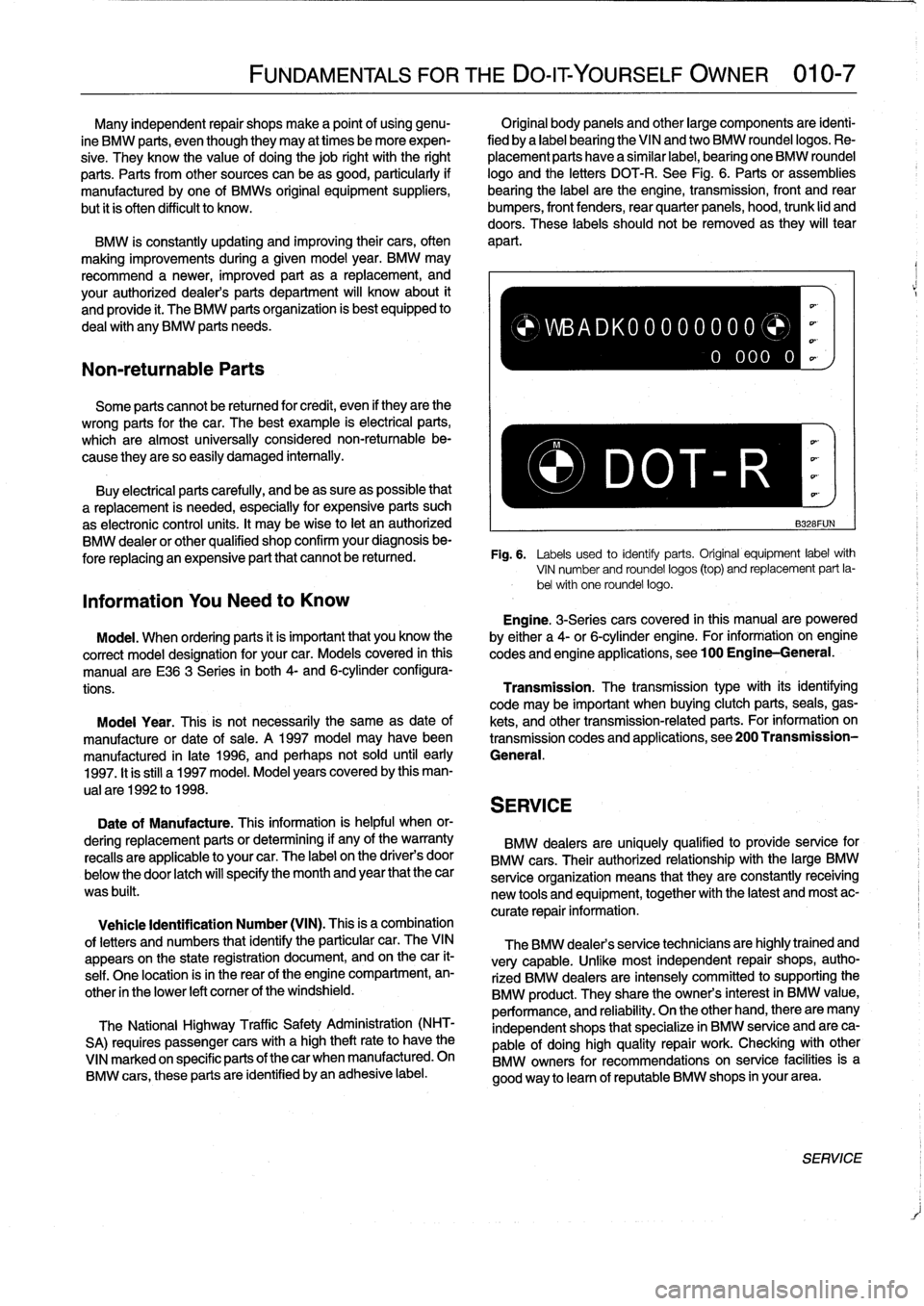
Fig
.
6
.
Labels
used
to
identiy
parts
.
Original
equipment
labelwith
VIN
number
and
roundel
logos
(top)
and
replacement
part
la-
bel
with
one
roundel
logos
Information
You
Need
to
Know
Engine
.
3-Seriescars
covered
in
this
manualare
powered
Model
.
When
ordering
parts
it
is
important
that
you
know
the
by
either
a
4-or
6-cylinder
engine
.
For
information
-
on
engine
correct
model
designation
for
your
car
.
Models
covered
in
this
codes
and
engine
applications,
see100
Engine-General
.
manual
are
E36
3
Series
in
both
4-
and
6-cylinderconfigura-
tions
.
Transmission
.
The
transmissiontype
with
its
identifying
code
may
be
important
when
buying
clutch
parts,
seals,
gas
Moda¡
Year
.
This
is
not
necessarily
the
same
as
date
of
kets,
and
othertransmission-relatedparts
.
For
information
on
manufacture
or
date
of
sale
.
A
1997
model
may
havebeen
transmission
codes
and
applications,
see200
Transmission
manufactured
in
late
1996,
and
perhaps
not
sold
until
early
General
.
1997
.
It
is
still
a1997
model
.
Model
years
covered
by
this
man-
ual
are
1992
to
1998
.
SERVICE
Date
of
Manufacture
.
This
information
is
helpful
when
or-
dering
replacement
parts
or
determining
if
any
of
the
warranty
BMW
dealers
are
uniquely
qualified
to
provide
service
for
recalls
are
applicable
to
your
car
.
The
label
on
the
driver's
door
BMW
cars
.
Their
authorized
relationship
with
the
large
BMW
below
the
door
latch
will
specify
the
month
and
year
that
the
car
serviceorganization
means
that
they
are
constantly
receiving
was
built
.
new
tools
and
equipment,
together
with
the
latest
and
most
ac-
curate
repair
information
.
Vehicle
Identification
Number
(VIN)
.
This
is
a
combination
of
letters
and
numbers
that
identify
the
particular
car
.
TheVIN
appears
on
the
state
registration
document,
and
on
thecar
it-
self
.
One
location
isin
the
rear
of
the
engine
compartment,
en-
other
in
the
lower
left
comer
of
the
windshield
.
The
National
Highway
Traffic
Safety
Administration
(NHT-
SA)
requires
passenger
cars
with
a
high
theftrateto
have
the
VINmarked
on
specific
parts
of
thecar
when
manufactured
.
On
BMW
cars,
these
parts
are
identified
byan
adhesive
label
.
)WBADK00000000
0
000
0
The
BMW
dealers
service
technicians
are
highlytrained
and
very
capable
.
Unfke
most
independent
repair
shops,
autho-
rized
BMW
dealers
are
intensely
committed
tosupporting
the
BMW
product
.
They
share
the
owners
interest
in
BMW
value,
performance,
and
reliability
.
On
the
other
hand,
there
are
many
independent
shops
that
specialize
in
BMW
service
and
are
ca-
pable
of
doing
high
quality
repair
work
.
Checking
with
other
BMW
owners
for
recommendations
on
service
facilitiesis
a
good
way
to
leam
of
reputable
BMW
shops
in
yourarea
.
SERVICE
Page 59 of 759
110
Engine
Removal
and
Installation
GENERAL
.
.
.
.
.......
.
.
.
..........
.
...
110-1
Engine,
removing
and
installing
(4-cylinder
engines)
.
..
.....
..
...........
110-1
ENGINE
REMOVAL
AND
INSTALLATION
110-1
Engine,
removing
and
installing
(6-cylinder
engines)
..
...
...
..
.....
..
....
110-4
GENERAL
Some
special
tools
are
required
for
removal
and
installation
of
the
engine
.
Be
sure
to
have
the
necessary
equipment
on
hand
before
starting
thejob
.
CAUTION-
"
Engine
removal
requires
disconnecting
the
bat-
tery
.
This
may
erase
any
system
fault
code(s)
that
havebeen
stored
in
control
unit
memories
.
Check
forfault
codes
prior
to
disconnecting
the
battery
cables
.
"
If
the
Check
Engine
lightis
illuminated
with
the
engine
running,
see
100
Engine-General
for
On-Board
Diagnostics
(08D)
fault
code
infor-
mation
.
"
If
any
other
system
faults
have
been
detected,
as
indicated
by
an
illuminated
ANTI
LOCK,
SRS
or
AST
warning
light,
see
the
appropriate
repair
group
inthis
manual
or
an
authorized
BMW
dealer
for
more
information
on
fault
codes
.
ENGINE
REMOVALAND
INSTALLATION
Engine,
removing
and
installing
(4-cylinder
engines)
Cover
al¡
painted
surfaces
before
beginning
theremoval
procedure
.
Asan
aid
to
installation,
label
al¡
components,
wires,
and
hoses
before
removing
them
.
Do
not
reuse
gas-
kets,
O-rings
or
seals
during
reassembly
.
WARNING
-
Due
to
risk
of
personal
injury,
be
sure
the
engine
is
cold
before
beginning
the
removalprocedure
.
1.
Disconnect
negative
(-)
cable
from
battery
in
luggage
compartment
.
0011969
CAUTION-
Prior
to
disconnecting
the
battery,
read
the
battery
disconnection
cautions
given
at
the
front
of
this
manual
on
page
viii
.
ENGINE
REMOVAL
AND
INSTALLATION
110-1
2
.
Remove
transmission
from
car
.
See230
Manual
Transmission
or
240
Automatic
Transmission
.
3
.
Remove
enginehood
or
place
hood
in
service
positíon
.
See
410
Fenders,
Engine
Hood
.
NOTE-
tt
is
notnecessary
to
remove
the
engine
hood,
but
it
is
helpful
and
will
make
engine
removal
and
installation
easier
.
4
.
Remove
splash
guard
under
engine,
if
applicable
.
5
.
Unbolt
ignition
coil
assembly
from
bracket
on
strut
tow-er
.
Disconnect
wiring
to
ignition
cofs,
then
place
coil
assembly
on
engine
.
6
.
Disconnect
al¡
cables
and
harness
connectors
at
throt-
tle
housing
.
7
.
Unbolt
andremove
complete
air
cleaner
housing
with
mass
air
flow
sensor,
disconnecting
and
labeling
con-
nectors,
ducting
and
hoses
asnecessary
.
See
Fig
.
1
.
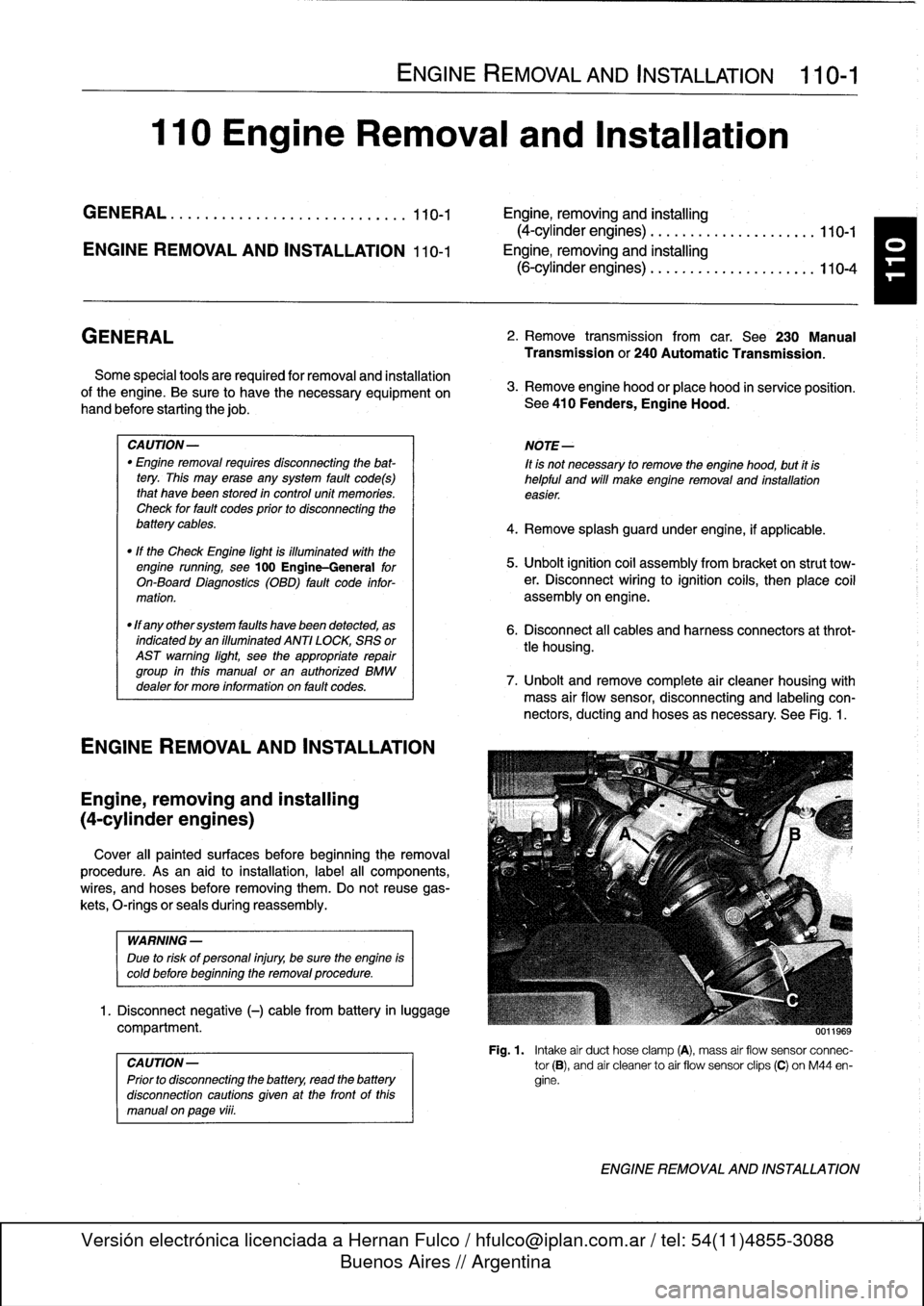
Fig
.
1
.
Intake
air
duct
hose
clamp
(A),
mass
air
flow
sensor
connec-
tor
(B),
and
air
cleanerto
air
flow
sensor
clips
(C)
on
M44
en-
gine
.
ENGINE
REMOVAL
AND
INSTALLATION
Page 62 of 759
110-
4
ENGINE
REMOVAL
AND
INSTALLATION
Engine,
removing
and
installing
(6-cylinder
engines)
Engineremoval
procedures
for
the
various
6-cylinder
en-
gines
arecovered
in
this
section
.
Most
steps
in
theproce-
dures
are
similar
or
the
same
for
al¡
engines
.
Specific
differences
that
apply
are
noted
at
the
beginning
of
each
step
.
Be
sure
to
cover
all
painted
surfaces
before
beginning
the
removal
procedure
.
As
an
aid
to
installation,
label
all
compo-
nents,wires,
and
hoses
before
removing
them
.
Do
not
reuse
gaskets,
O-rings
or
seals
during
reassembly
.
WARNING
-
Due
to
risk
of
personal
injury,
be
sure
the
engine
is
cold
before
beginning
the
removalprocedure
.
1
.
Disconnect
negative
(-)
battery
cable
in
luggage
com-
partment
.
CAUTION-
Prior
to
disconnecting
the
battery,
read
the
battery
disconnection
cautions
given
at
the
front
of
this
manual
onpage
vi¡¡
.
2
.
Remove
engine
hood
or
place
hood
in
service
position
.
See410
Fenders,
Engine
Hood
.
NOTE-
1t
is
not
necessary
to
remove
the
engine
hood,
but
it
is
helpful
and
will
make
engine
removal
and
installation
easier
.
3
.
Remove
splash
guardunder
engine,
if
applicable
.
4
.
Remove
transmission
from
car
.
See
230
Manual
Transmission
or
240Automatic
Transmission
.
5
.
Remove
vacuum
hosefrom
brake
booster
on
bulkhead
.
Cover
hole
in
booster
and
plug
hose
end
.
6
.
Remove
intake
air
plenum
panel
in
rear
of
engine
com-
partment
.
See
640
Heating
and
AirConditioning
.
7
.
Remove
ground
strap
from
timing
case
cover,
if
appli-
cable
.
8
.
Remove
top
enginecovers
and
disconnect
ignition
coil
harness
connectors
.
Working
at
fuel
injectors,
pry
open
small
wire
clipsat
each
injector
.
Remove
main
harness
hold-down
nuts
and
lift
completeharness
away
.
See
Fig
.
7
.
ENGINE
REMOVAL
AND
INSTALLATION
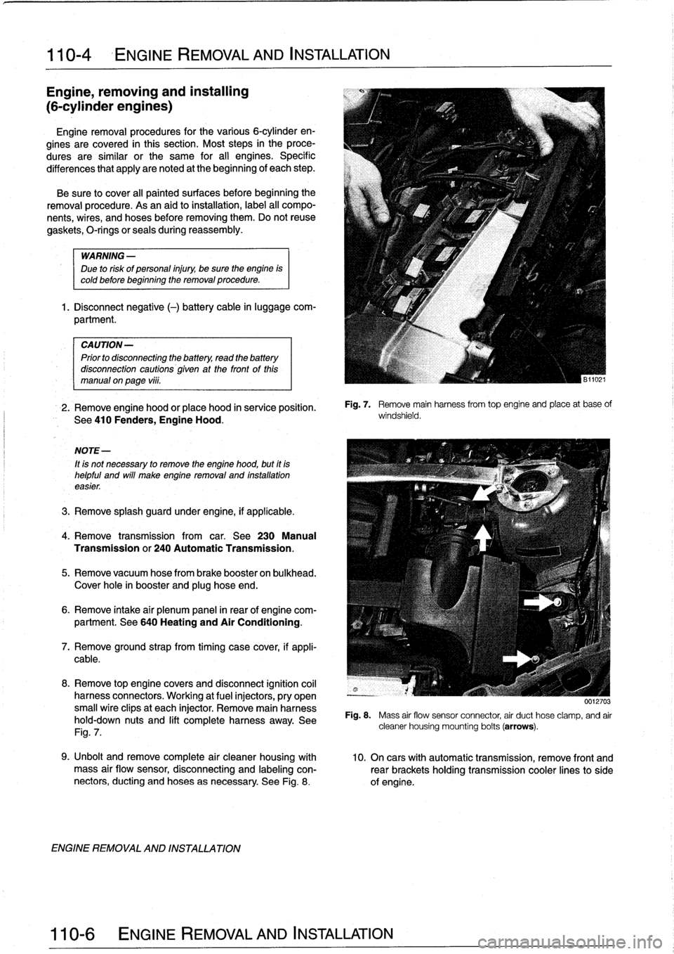
Fig
.
7
.
Remove
mainharnessfrom
top
engine
and
place
at
base
of
windshield
.
0012703
Fig
.
8
.
Mass
air
flow
sensor
connector
air
duct
hose
clamp,
and
air
cleaner
housing
mounting
bolts
(arrows)
.
9
.
Unbolt
andremove
complete
air
cleaner
housing
with
10
.
On
cars
with
automatic
transmission,
remove
front
and
mass
air
flow
sensor,
disconnecting
and
labeling
con-
rearbrackets
holding
transmission
cooler
linesto
side
nectors,
ducting
and
hoses
asnecessary
.
See
Fig
.
8
.
of
engine
.
Page 304 of 759
400-2
BODY-GENERAL
4-door
Sedan
Coupe
-
saas3
.7""
351
/
37
.3
O
I
x
`-193
267
o
oa
'3281
model
"M3
model
Convertible
BODYASSEMBLY
55
ass
.e
iss
""
-
66
.9
-
Fig
.
2
.
E36
body
dimensíons
.
BODY
ASSEMBLY
29
.4
29
4
The
BMW
3
Series
chassis
is
a
unibodydesign
constructed
ofhigh
strength
steel
.
Attaching
parts,
suchas
the
front
fend-
ers,
rear
quarter
panels,
doors,
trunk
lid
and
hood
are
also
constructed
of
steel
.
706
.31108
.7"
I
38
.5
174
.5
174
.5
O
oo
196
.3/106
.7'
"
35_5
1.
.
55
.9,566
".
106
.3/196
.7""
i.
358
-1745-
55
9/56
3'/56
6"
-
J
0013099
Windows
bonded
flush
to
the
body
and
the
guided
flow
of
cooling
air
into
the
engine
compartment
provide
a
good
coeffi-
cient
of
drag(CD)
.
TheE36
cars
have
a
CD
of
approximately
0
.30for
the
sedan
and
coupe
models,
and
0
.35
for
the
con-
vertible
models
:
The
exterior
panels
are
corrosion-resistant
zinc
coated
steel
.
The
front
fenders
are
bolted
on
and
easily
replaceabie
.
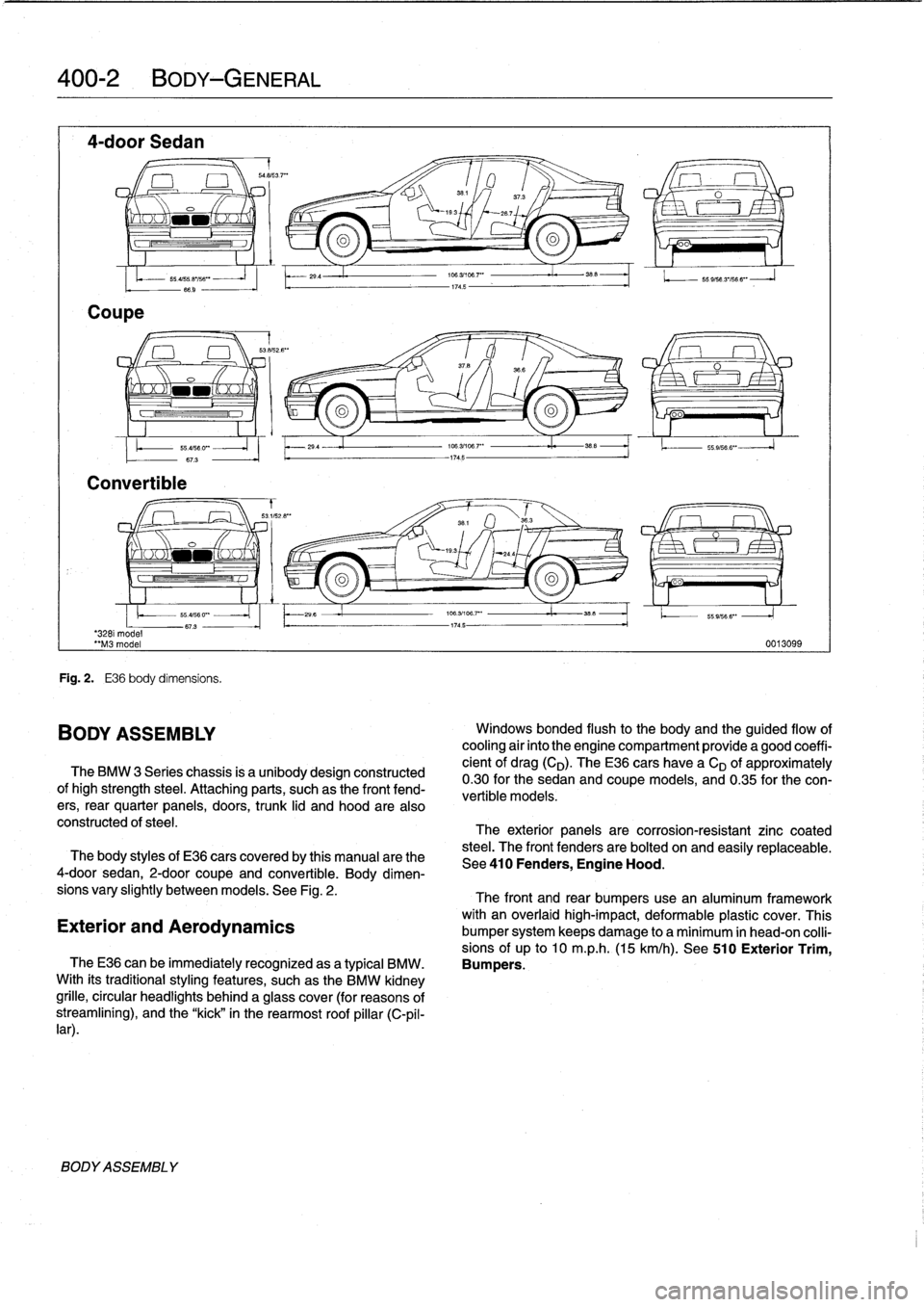
The
body
styles
of
E36
cars
coveredby
this
manual
arethe
See410
Fenders,
Engine
Hood
.
4-door
sedan,
2-door
coupe
and
convertible
.
Body
dimen-
sions
vary
slightly
betweenmodels
.
See
Fig
.
2
.
The
front
and
rear
bumpers
use
an
aluminum
framework
with
an
overlaid
high-impact,
deformable
plastic
cover
.
This
Exterior
and
Aerodynamics
bumper
system
keeps
damage
to
a
minimum
in
head-on
colli-
sions
of
up
to
10
m
.p
.h
.
(15
km/h)
.
See
510
Exterior
Trim,
TheE36
can
be
immediatelyrecognized
asa
typical
BMW
.
Bumpers
.
With
its
traditionalstyling
features,
suchas
the
BMW
kidney
grille,
circular
headlights
behind
a
glass
cover
(for
reasons
of
streamliníng),
and
the
"kick"
in
the
rearmost
roof
pillar
(C-pil-
lar)
.
Page 309 of 759
GENERAL
This
repair
group
covers
replacement
of
the
front
fenders
and
removal
and
installation
of
the
engine
hood
.
NOTE-
The
body
is
painted
at
the
factoryafter
assembly
.
Re-
alignment
of
body
panels
may
expose
unpainted
metal
.
Paint
all
exposed
metal
once
the
work
fs
complete
.
FRONT
FENDERS
Front
fender,
removing
and
installing
1
.
Raise
hood
.
Raise
and
safely
support
front
of
vehicle
.
WARNING
-
"
When
raising
thecar
using
a
floor
jack
or
a
hy-
draulic
lift,
carefully
position
the
jack
pad
to
pre-
vent
damaging
thecar
body
.
A
suitable
liner
(wood,
rubber,
etc
.)
should
be
placed
between
the
jack
and
the
car
to
prevent
body
damage
.
"
Watch
the
jack
closely
.
Make
sure
it
stays
stable
and
does
not
shift
or
tilt
.
As
the
car
is
raised,
the
car
may
roll
slightly
and
the
jack
may
shift
.
2
.
Remove
front
wheel
.
Remove
inner
plastic
liner
from
wheel
well
.
3
.
Remove
front
bumper
.
See510
Exterior
Trim,
Bumpers
.
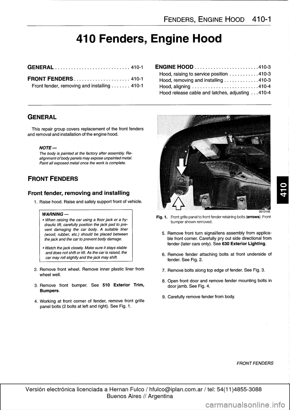
4
.
Working
atfront
corner
of
fender,
remove
front
grille
panel
bolts
(2
bolts
at
left
and
right)
.
See
Fig
.
1
.
FENDERS,
ENGINE
HOOD
410-1
410
Fenders,
Engine
Hood
GENERAL
...............
.
.
.
.
.
.
.
.
.
.
.
..
410-1
ENGINE
HOOD
.
.
.
.
.
.
.
.
.
.
.
.
.
.
.
.
.
.
.
...
.
.410-3
Hood,
raising
to
service
position
.
.
.
.
.
.
.
.
...
410-3
FRONTFENDERS
........
.
.
.
.
.
.
.
.
.
.
.
.
.410-1
Hood,
removin
and
installin
410-3
Front
Pender,
removing
and
installing
.
.
.
....
410-1
Hood,
aligning
...
.
.
.
.
.
.
.
.....
.
.
.
.
.
.
.
...
410-4
Hood
release
cable
and
latches,
adjusting
...
410-4
001
.145
Fig
.
1
.
Front
grille
panel
to
front
fender
retaining
bolts
(arrows)
.
Front
bumpershown
removed
.
5
.
Remove
front
turn
signalliens
assembly
from
applica-
ble
front
corner
.
Carefully
pryout
side
directional
from
fender
(later
cars
only)
.
See
630
Exterior
Lighting
.
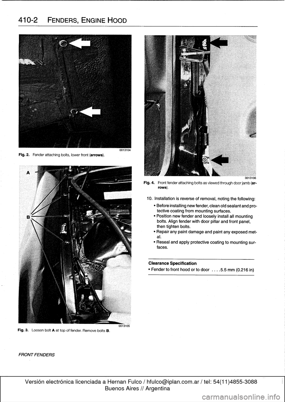
6
.
Remove
fender
attaching
bolts
atfront
underside
of
fender
.
See
Fig
.
2
.
7
.
Remove
bolts
along
top
edge
of
fender
:
See
Fig
.
3
.
8
.
Open
front
door
and
remove
fender
mounting
bolts
in
door
jamb
.
See
Fig
.
4
.
9
.
Carefully
remove
fender
from
body
.
FRONTFENDERS
Page 310 of 759
410-2
FENDERS,
ENGINE
HOOD
Fig
.
2
.
Fender
attaching
bolts,
lower
front
(arrows)
.
Fig
.
3
.
Loosen
bolt
A
at
top
offender
.
Remove
bolts
B
.
FRONTFENDERS
0013104
0013105
0013106
Fig
.
4
.
Front
fender
attaching
bolts
as
viewed
through
doorjamb
(ar-
rows)
.
10
.
Installation
is
reverse
of
removal,
noting
the
following
:
"
Before
installing
new
fender,
clean
old
sealant
and
pro-
tective
coating
from
mounting
surfaces
.
"
Position
new
fender
and
loosely
install
all
mounting
bous
.
Align
fender
with
door
pillar
and
front
panel,
then
tighten
bolts
.
"
Repair
any
paint
damage
and
paint
any
exposed
met-
al
.
"
Reseal
and
apply
protective
coating
to
mounting
sur-
faces
.
Clearance
Specification
"
Fender
to
front
hood
or
to
door
.
...
5
.5
mm
(0
.216
ín)
Page 311 of 759
ENGINE
HOOD
Hood,
raising
to
service
position
CA
UTION-
Do
not
switch
on
the
windshield
wipers
wlth
the
engine
hood
raised
.
As
a
precaution,
remove
the
wiper
motor
fuse
.
See
610
Electrical
Compo-
nent
Locations
.
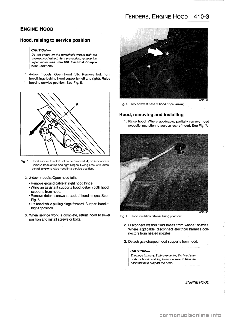
1
.
4-door
models
:
Open
hood
fully
.
Remove
bolt
from
hood
hinge
behind
hood
supports
(left
and
right)
.
Raise
hood
to
service
position
.
See
Fig
.
5
.
2
.
2-door
models
:
Open
hood
fully
.
Fig
.
5
.
Hood
support
bracket
boltto
be
removed
(A)
on
4-door
cars
.
Remove
bolts
at
left
and
right
hinges
.
Swing
bracket
in
direc-
tion
of
arrow
to
raise
hood
into
service
position
.
"
Remove
ground
cable
atright
hood
hinge
.
"
Whilean
assistant
supports
hood,
detach
both
hood
supportsfrom
hood
.
"
Remove
detent
screws
at
back
of
hood
hinges
.
See
Fig
.
6
.
"
Lift
hood
while
pulling
hinge
forward
.
Support
hood
at
higher
position
.
3
.
When
service
work
is
complete,
return
hood
to
lower
position
and
instaf
screws
or
bolts
.
FENDERS,
ENGINE
HOOD
410-
3
Fig
.
6
.
Torx
screw
at
base
of
hood
hinge
(arrow)
.
Hood,
removing
and
installing
0013147
1
.
Raise
hood
.
Where
applicable,
partially
remove
hood
acoustic
insulation
to
access
rear
of
hood
.
See
Fig
.
7
.
Fig
.
7
.
Hood
insulation
retainer
being
pried
out
3
.
Detachgas-charged
hood
supportsfrom
hood
.
CAUTION
-
The
hood
is
heavy
.
Before
removing
the
hood
sup-
ports
or
hood
retainingbolts,
be
sure
to
have
an
assistant
help
support
the
hood
.
0013148
2
.
Disconnect
washer
fluid
hoses
from
washer
nozzles
.
Where
applicable,
disconnect
electrical
harness
con-
nectors
fromheated
nozzles
.
ENGINE
HOOD
Page 312 of 759
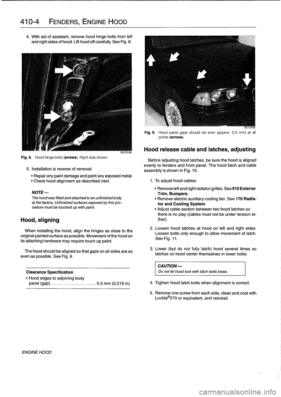
410-4
FENDERS,
ENGINE
HOOD
4
.
With
aid
of
assistant,
remove
hood
hinge
bolts
from
left
and
Rght
sides
of
hood
.
Lift
hood
off
carefully
See
Fig
.
8
.
Fig
.
8
.
Hood
hinge
bolts
(arrows)
.
Right
side
shown
.
5
.
Installation
is
reverse
of
removal
.
NOTE-
The
hood
was
fitted
and
attached
to
an
unfinished
body
at
the
factory
.
Unfinished
surfaces
exposed
by
this
pro-
cedure
must
betouchedup
wfth
pafnt
.
Hood,
aligning
ENGINE
HOOD
0013149
6013150
Fig
.
9
.
Hood
panel
gaps
should
be
even
(approx
.
5
.5
mm)
at
all
points
(arrows)
.
Hood
release
cable
and
latches,
adjusting
Before
adjusting
hood
latches,
be
sure
the
hood
is
aligned
evenly
to
fenders
and
front
panel
.
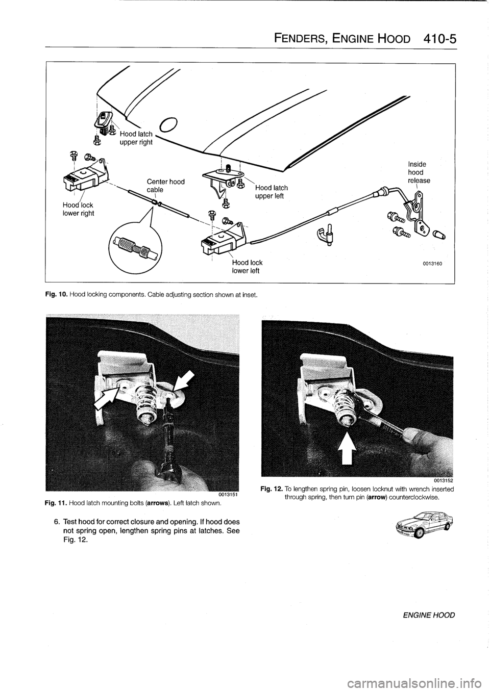
The
hood
latch
and
cable
assembly
is
shown
in
Fig
.
10
.
"
Repair
any
paint
damage
and
paint
any
exposed
metal
.
"
Check
hood
alignment
as
described
next
.
1
.
To
adjust
hood
cables
:
When
installing
the
hood,
align
the
hinges
as
close
to
the
original
paintedsurface
as
possible
.
Movement
of
the
hood
on
its'attaching
hardware
may
require
touch-up
paint
.
The
hood
should
be
aligned
so
that
gapson
all
sides
areas
even
as
possible
.
See
Fig
.
9
.
Clearance
Specification
"
Hood
edges
to
adjoining
body
panel
(gap)
........
..
..
..
.....
.5
.5
mm
(0.216
in)
"
Remove
left
and
right
radiator
grilles
.
See
510
Exterior
Trim,
Bumpers
.
"
Remove
electric
auxíliary
cooling
fan
.
See
170
Radia-
tor
and
Cooling
System
.
"
Adjust
cable
section
between
two
hood
latches
so
there
is
no
play
(cables
must
not
be
under
tension
ei-
ther)
.
2
.
Loosen
hood
latches
at
hood
on
left
and
right
sides
.
Loosen
bolts
only
enough
to
allow
movement
of
latch
.
See
Fig
.
11
.
3
.
Lower
(but
do
not
fully
latch)
hood
severa¡
times
so
latches
on
hood
center
themselves
in
lower
locks
.
CA
UTION-
Do
not
let
hood
fockwith
latchbolts
loose
.
4
.
Tighten
hood
latch
bolts
when
alignment
is
correct
.
5
.
Remove
one
screw
fromeach
side,
clean
and
coat
with
Loctite
O
270
or
equivalent,
and
reinstall
.
Page 313 of 759
Center
hood
,
00--&---
cable
Hood
latch
_
I
upperleft
Fig
.
10
.
Hood
locking
components
.
Cable
adjusting
section
shown
at
inset
.
Fig
.
11
.
Hood
latch
mounting
bolts
(arrows)
.
Left
latch
shown
.
Hood
lock
0013160
lower
left
6
.
Test
hood
for
correct
closure
and
opening
.
If
hooddoes
notspring
open,
lengthen
springpins
at
latches
.
See
Fig
.
12
.
FENDERS,
ENGINE
HOOD
410-5
001aio
Fig
.
12
.
To
lengthen
spring
pin,
loosen
locknut
with
wrench
inserted
through
spring,
then
turn
pin
(arrow)
counterclockwise
.
ENGINE
HOOD