Repair group 130 BMW 318i 1994 E36 User Guide
[x] Cancel search | Manufacturer: BMW, Model Year: 1994, Model line: 318i, Model: BMW 318i 1994 E36Pages: 759
Page 303 of 759
GENERAL
.
....
.
.
.
.
.
.......
.
.
.
.
.
...
.
.
.
400-1
INTERIOR
EQUIPMENT
......
.
.
.
.......
400-4
Seats
and
Seatbelts
.
.
.
.
.
.
.....
.
.
.
.
.
..
.
..
400-4
BODY
ASSEMBLY
.
.
.
.
.
.....
.
.
.
.
.
.
.
.
.
.
.400-2
Instruments
and
Controls
.
..
....
.
.
.
.
.
.
.
...
400-4
Exterior
and
Aerodynamics
....
.
.
.
.
.
.
.
.
.
.
.
400-2
Central
Body
Electronics
.......
.
.
.
...
.
...
400-5
Coupe
Models
..
.
.
.
.
.
.......
.
.
.
.
.
.
.
.
.
..
400-3
Electronic
Immobilization
System
.
.
.
...
.
...
400-5
Convertible
Models
.
.
.
.
.
.
.
.....
.
.
.
.
.
.
.
..
400-3
Heating
and
Air
Conditioning
.
...
.
.
.
.
.
.
.
...
400-6
GENERAL
This
section
covers
system
descriptions
and
general
ser-
vice
information
for
the
repair
groupsfound
in
4
Body
and
5
Body
Equipment
.
When
working
or
servicing
cars
equipped
with
SRS
air-
bag(s),
the
following
precautions
must
be
observed
to
prevent
injury
.
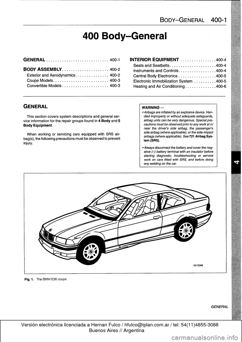
F19
.1
.
The
BMW
E36
coupe
.
400
Body-General
BODY-GENERAL
400-1
WARNING
-
"
Airbags
are
inflated
by
an
explosivedevice
.
Han-dled
improperly
or
without
adequate
safeguards,
airbag
units
can
be
very
dangerous
.
Special
pre-cautions
must
be
observed
prior
to
any
work
ator
near
the
driver's
side
airbag,
the
passenger's
side
airbag
(where
applicable),
or
the
side-impact
aírbags
(where
applicable)
.
See
721
Airbag
Sys-
tem
(SRS)
.
"
Always
disconnect
the
battery
and
cover
the
neg-
ative
(-)
battery
terminalwith
an
insulator
before
starting
diagnostic,
troubleshooting
or
service
work
oncars
fitted
with
SRS,
and
before
doíng
any
welding
on
the
car
.
0013098
GENERAL
Page 323 of 759
GENERAL
.
.
.
.
.
.
.
.
.
...
.
..
.
...
.
.........
510-1
Front
bumper
impact
absorber,
replacing
....
510-4
Rear
bumper,
removing
and
installing
.....
.510-4
OUTSIDE
REAR
VIEW
MIRRORS
.
...
.
.....
510-1
Rear
bumper
impact
absorber,
replacing
...
.
510-6
Outside
mirrorglass,
replacing
.
.
.........
510-1
Bumper
height,
adjusting
...
.
...
.
...
.
.
.
.
.
510-6
Outside
mirror
housing,
removing
and
installing
....
.
.....
.
.
.
.
.
.
510-1
EXTERIOR
TRIM
...
.
.
.
.
.
.
.
.
.
.
.
...
.
.
.
.
.
510-6
Outside
mirror,
removing
and
installing
.
.
.
.
.
510-2
BMW
embiem,
removing
and
installing
.
.
.
.
.
.
510-7
Body
side
molding,
replacing
.
.
.
.
.
.
.
.
.
.
.
.
.
510-7
BUMPERS
.
.
.
.
.
....
.
.....
.
.....
.
.
.
.
.
.
510-3
Radiator
grille,
removing
and
installing
.
.
.
.
.
.510-7
Front
bumper,
removing
and
installing
.
.
.
.
.
.
510-3
Front
panel,
removing
and
installing
...
.
.
.
.
.
510-7
GENERAL
510
Exterior
Trim,
Bumpers
This
repair
group
includes
repair
information
for
the
outside
rear
view
mirror,
front
and
rear
bumpers,
and
the
easily
re-
movable
exterior
trim
parts
.
OUTSIDE
REAR
VIEW
MIRRORS
The
remove
controlled
mirrors
come
in
two
styles
:
heated
and
unheated
.
Many
of
the
mirror
components
are
separately
available
from
an
authorized
BMW
dealer,
including
the
glass
and
outside
plastic
housing
.
Outside
mirror
glass,
replacing
CAUTION-
Mirror
shouldbe
ator
above
room
temperature
before
removal
.
Otherwise,
small
plastic
parts
or
glass
will
break
.
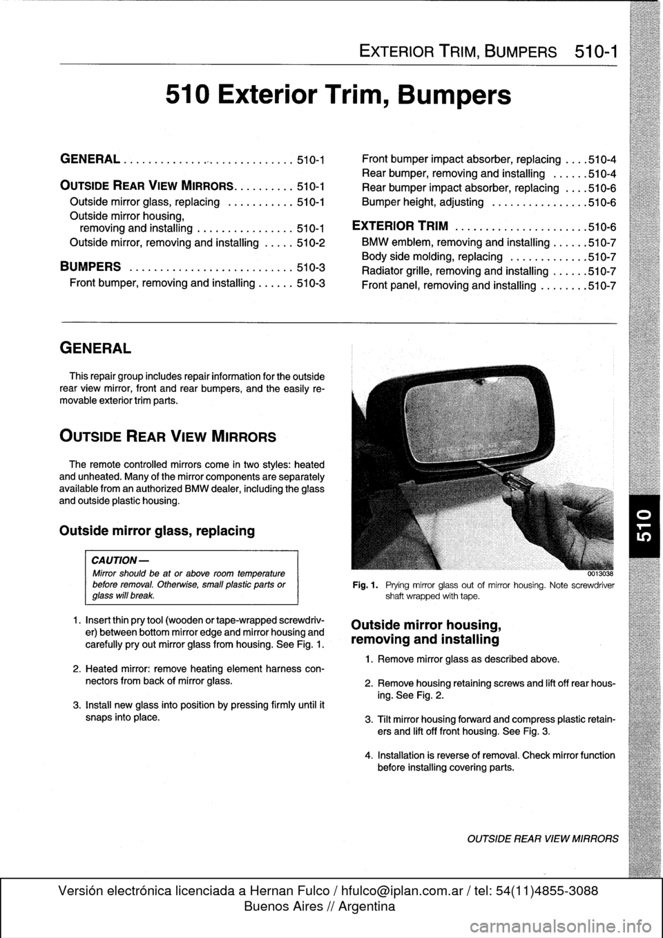
1
.
Insert
thin
pry
tool
(wooden
or
tape-wrapped
screwdriv-
er)
between
bottom
mirror
edge
and
mirror
housing
and
carefully
pry
out
mirror
glass
from
housing
.
See
Fig
.
1
.
2
.
Heated
mirror
:
remove
heating
element
harness
con-
nectors
from
back
of
mirror
glass
.
3
.
Install
new
glass
into
position
by
pressing
firmly
until
it
snaps
into
place
.
EXTERIOR
TRIM,
BUMPERS
510-1
00130
..
Fig
.1
.
Prying
mirror
glass
out
of
mirror
housing
.
Note
screwdriver
shaft
wrapped
with
tape
.
Outside
mirror
housing,
removing
and
installing
1
.
Remove
mirror
glass
as
described
above
.
2
.
Remove
housing
retaining
screws
and
lift
off
rear
hous-
ing
.
See
Fig
.
2
.
3
.
Tilt
mirror
housing
forward
and
compress
plastic
retain-
ers
and
lift
off
front
housing
.
See
Fig
.
3
.
4
.
Installation
is
reverse
of
removal
.
Check
mirror
function
before
installing
covering
parts
.
OUTSIDE
REAR
VIEW
MIRRORS
Page 387 of 759
610
Electrical
Component
Locations
GENERAL
...........
.
.
.
.
.
.
.
.
.
........
610-1
FOSE
POSITION
TABLES
..
.
.
.
.
.
.....
.
610-19
FUSE
AND
RELAY
POSITIONS
.
...
.
.
.
.
.
610-1
Fuse
Positions
.
.
.
................
.
.
.
.
.
610-1
Relay
Positions
.
.
.
.....
.
.
.
........
.
.
.
.
.
610-2
Auxiliary
RelayPanel
.....
.
...
.
........
.
610-2
SplicePanel,
Left
.
.
.
...
.
.
.
...
.
........
.
610-2
SplicePanel,
Right
.
.
.
.
.
.
.
.
...
.
.........
610-3
COMPONENT
LOCATIONS
.
.
.
.
.......
.
.610-3
Component
Location
Table
.
.
.
.
.
.
.........
610-9
GENERAL
FUSE
AND
RELAY
POSITIONS
This
repair
group
covers
f
use,
relay,
and
control
module
lo-
The
front
power
distribution
box,
an
auxiliary
relay
panel,cation
information
.
Electrical
equipment
and
accessories
in-
and
two
auxiliary
splice
panels
contain
most
of
the
fuses
and
stalled
varies
depending
on
model
and
model
year
.
Always
relays
in
E36
vehicles
.
Refer
to
the
component
location
later
confirm
that
the
proper
electrical
component
has
been
identi-
in
this
section,
as
well
as
the
tables
at
the
end
of
this
repair
fied
by
using
the
electrical
wiring
diagrams
.
group
for
electrical
component
location
.
WARNING
-
On
cars
equipped
with
airbags,
special
precautionsapply
to
any
electrical
system
testing
orrepair
.
Air-
bag
units
areexplosive
devices
and
mustbe
han-
dled
with
extremecare
.
Before
starting
any
work
onan
airbag
equipped
car,
refer
to
the
wamings
and
cautions
in
721
Airbag
System
(SRS)
.
CAUTION
-
"
Prior
to
disconnectiog
the
battery,
read
the
bat-
tery
disconnection
cautions
given
at
the
front
of
this
manual
on
page
viii
.
"
Relay
and
fuse
positions
are
subject
to
changeand
may
varyfrom
car
to
car
.
If
questions
arise,
an
authorized
BMW
dealer
is
the
best
source
for
the
most
accurate
and
up-to-date
information
.
"
A
good
way
to
verify
a
relay
position
isto
com-
pare
the
wiring
colors
at
the
relay
socket
to
thecolors
indicated
on
the
wiring
diagrams
located
at
the
rear
of
this
manual
.
"
Always
switchthe
ignition
off
and
disconnect
the
negative
(-)
battery
cable
before
removing
any
electrical
components
.
"
Connect
and
disconnect
ignition
system
wires,
multiple
connectors,
and
ignition
test
equipment
leads
only
while
the
ignition
is
switched
off
.
"
Only
usea
digital
multimeter
for
electrical
tests
.
ELECTRICAL
COMPONENT
LOCATIONS
610-1
TABLES
a
.
E36Component
Locations
...........
.
.
..
...
610-10b
.
1992
E36
Fuse
Positions
..........
..
.
.
.....
610-20c
.
1993
E36
Fuse
Positions
..........
..
..
.
....
610-22d
.
1994
E36
Fuse
Positions
.........
...
.......
610-24e
.
1995
E36
Fuse
Positions
.........
...
.......
610-26
f
.
1996
E36
Fuse
Positions
.........
...
.......
610-28g
.
1997-1998
E36
Fuse
Positions
..
.
..
...
.......
610-30
Fuse
Positions
CAUTION
-
"
Replace
fuses
with
those
of
the
same
rating
.
In-
stalling
a
fuse
with
higher
rating
can
lead
to
cir-
cuit
failure
and
may
also
start
a
fire
.
"
Relay/fuse
positions
vary
by
model
and
equip-
ment
.
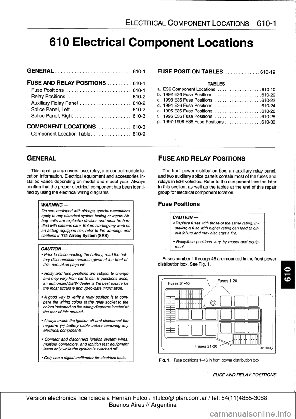
Fuses
number
1
through
46
are
mounted
in
the
front
power
distribution
box
.
See
Fig
.
1.
Fuses
31-46
~
Illlllllllll
°
-
Ilmmlmomlmoi
Fuses
1-20
(a
1
:1
E
El
~
~O!7
L~~n
4~
i
Fuses
21-30
Fig
.1.
Fuse
positions
1-46
in
front
power
distribution
box
.
0013034
FUSE
AND
RELAY
POSITIONS
Page 447 of 759
GENERAL
E36
cars
are
equipped
with
integrated
automatic
heating
and
air
conditioning
systems
.
Many
of
the
procedures
given
in
this
repair
group
require
that
the
A/C
refrigerant
charge
be
evacuated
using
specialized
equipment
.
See
A/C
System
Warningsand
Cautions
later
in
this
repair
group
.
HEATER
AND
CONTROLS
Blower
motor,
removing
and
installing
NOTE-
On
6-cylinder
cars,
the
plastic
top
enginecover
and
fuel
rail
covermustbe
removed
.
The
fuel
injectorhamess
re-
taining
screws
must
be
removed
and
the
harness
set
aside
.
The
engine
control
module
(ECM)
cover
must
be
removed,
the
control
unit
connectors
unplugged
and
the
harness
pulled
out
of
the
way
.
See
130
Fuel
Injection
.
1
.
Disconnect
negative
(-)
cable
from
battery
.
2
.
Open
hood
.
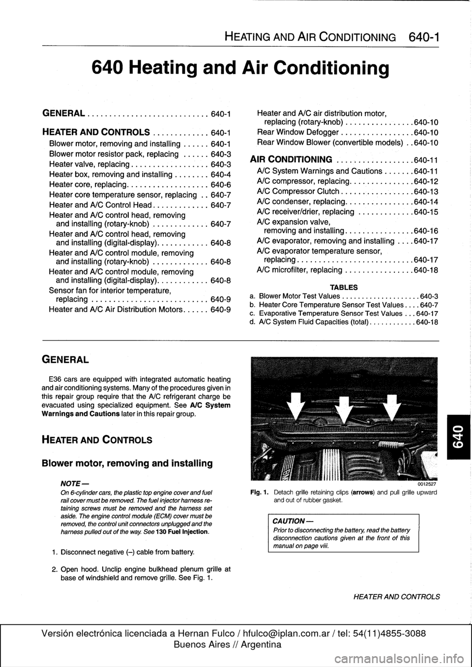
Unclip
engine
bulkhead
plenum
grille
at
base
of
windshíeld
and
remove
grille
.
See
Fig
.
1
.
HEATING
AND
AIR
CONDITIONING
640-1
640
Heating
and
Air
Conditioning
GENERAL
.
...
.
....
.
.
.
.
.
.
.
.
.
.......
.
.
.
640-1
Heater
andA/C
air
distribution
motor,
replacing(rotary-knob)
.
.
...
.
.
.
.......
.
640-10
HEATER
AND
CONTROLS
.
.....
.
.
.
.
.
.
.640-1
Rear
Window
Defogger
.
.
.
.
.
.
.
.
.
.
...
.
.
.
640-10
Blower
motor,
removing
and
installing
.
.
.
.
.
.
640-1
Rear
Window
Blower
(convertible
models)
.
.640-10
Blowermotor
resistor
pack,
replacing
.
.
.
.
.
.
640-3
AIR
CONDITIONING
.
.
.
.
.
.
.
.
.
.
.
.
.
.
.
.
.
.
640-11
Heater
valve,
replacing
...........
.
.
.
.
.
.
.
640-3
Heater
box,
removing
and
installing
.
.
.
.
.
.
.
.
640-4
A/CSystem
Warnings
and
Cautions
.
.
.
.
.
.
:640-11
Heater
core,
replacing
.....
.
.
:
....
.
.
.
.
.
.
.
640-6
A/C
compressor,
replacing
.
.
::.
:
:
.
.
.
.
.
.
.
.640-12
Heater
core
temperature
sensor,
replacing
.
.
640-7
A/C
Compressor
Clutch
.
.
.
.
.
.
.
:
.
.
.
.
.
.
.
.
.
640-13
Heater
andA/C
Control
Head
.
.
....
.
.....
.
640-7
A/C
condenser,
replacing
.
.
.
.
.
.
.
.
.
.
.
.
.
.
.
.
640-14
Heater
andA/C
control
head,
removing
A/C
receiver/drier,
replacing
.
.
.
.
.
.
.
.
.
.
.
.
.
640-15
and
installing
(rotary-knob)
.
.
....
.
......
640-7
A/C
expansion
valve,
Heater
andA/C
control
head,
removing
removing
and
installing
...
.
.....
.
.
.
.
.
.
.
640-16
and
installing
(digital-display)
.
.....
.
.....
640-8
A/C
evaporator,
removing
and
installing
.
.
..
640-17
Heater
andA/C
control
module,removing
A/C
evaporator
temperature
sensor,
and
installing
(rotary-knob)
.
.
...
.
.
.
.
.
.
.
.
640-8
replacing
.
.
.
.
.
.
..............
.
.
.
.
.
..
640-17
Heater
andA/C
control
module,removing
A/C
microfilter,
replacing
......
.
....
.
.
.
..
640-18
and
installing
(digital-display)
.
...
.
.
.
.
.
...
640-8
Sensor
fan
for
interior
temperature,
TABLES
replacing
.
.
.
....
.
.
.
.
.
.
.
.
.
.
.
.
.
.
.
.
.
.
.
.
640-9
a
.
Blower
Motor
Test
Values
.........
...
.
.
......
640-3
Heater
andA/C
AirDistribution
Motors
.
.
.
.
.
.
640-9
b
.
Heater
Core
Temperature
Sensor
Test
Values
...
.640-7
c
.
Evaporative
Temperature
Sensor
Test
Values
...
640-17
d
.
A/C
System
Fluid
Capacities
(total)
..
..........
640-18
0012527
Fig
.
1
.
Detach
grille
retaining
clips
(arrows)
and
pull
grille
upward
and
out
of
rubbergasket
.
CAUTION-
Prior
to
disconnectiog
the
battery,
read
the
battery
disconnection
cautionsgiven
at
the
front
of
this
manual
onpage
viii
.
HEATER
AND
CONTROLS