Engine sensor BMW 318i 1994 E36 Manual Online
[x] Cancel search | Manufacturer: BMW, Model Year: 1994, Model line: 318i, Model: BMW 318i 1994 E36Pages: 759
Page 250 of 759
300-2
SUSPENSION,
STEERING
AND
BRAKES-GENERAL
Steering
INTEGRATED
SYSTEMS
The
steering
linkage
connects
the
rack-and-pinion
unit
through
tie
rodsto
the
steering
arms
.
The
tie
rod
ends
allow
the
wheels
to
pivot
and
react
to
suspension
travel
.
Rear
Suspension
The
rear
axle
carrier
is
the
main
mounting
point
for
the
final
drive
housing
and
the
rear
suspension
components
.
Trailing
arms
locatethe
rear
wheels
and
anchorthe
springs,
shocks
and
stabilizer
bar
.
Driveaxies
with
constant-velocity
(CV)
joints
at
both
ends
transfer
power
from
the
differential
to
the
road
wheels
.
The
differential
is
mounted
to
the
rearaxle
carrier
through
rubber
mountsand
bushings
to
hele
isolate
drivetrain
noise
and
vibration
.
Brakes
E36
cars
areequipped
with
power
disc
brakes
with
an
inte-
gral
antilock
brakes
(ABS)
.
The
parking
brake
is
a
dual-drum
system
integrated
with
the
rear
brake
rotors
.
See
Fig
.
3
.
Power
assist
is
provided
by
a
vacuum
booster
when
the
en-
gine
is
running
.
The
brakepedal
pushrod
is
connected
directly
to
the
master
cylinder,
so
failure
of
the
vacuum
booster
does
not
normally
result
in
total
brake
failure
.
0012124
Each
disc
brakeuses
a
caliper
with
a
single
hydraulic
cylin-
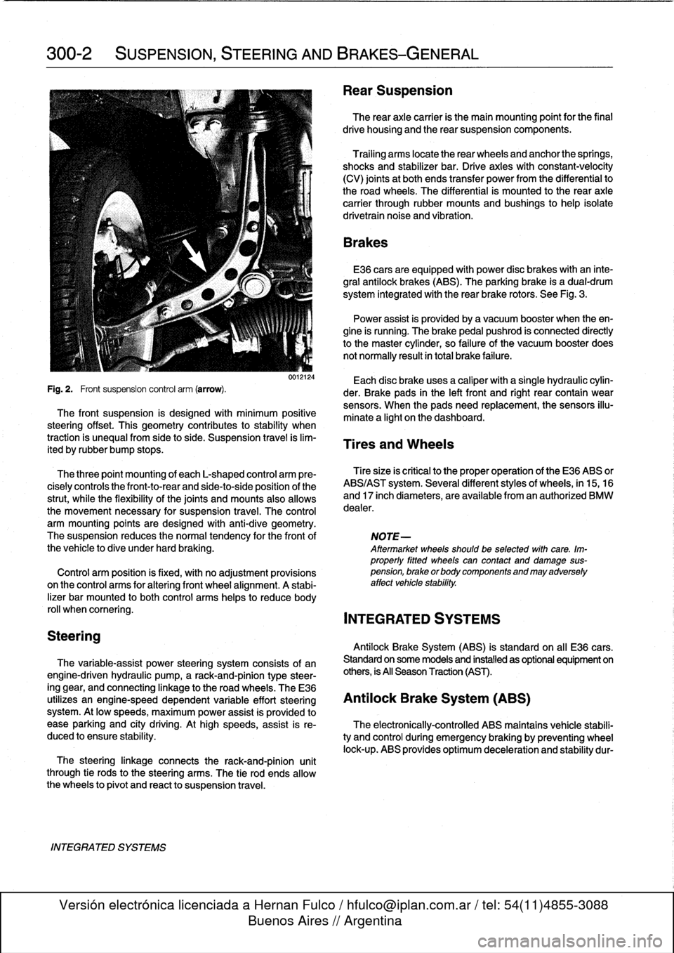
Fig
.
2
.
Front
suspension
control
arm
(arrow)
.
der
.
Brake
pads
in
the
left
front
and
right
rear
contain
wear
sensors
.
When
the
padsneed
replacement,the
sensors
illu-
The
front
suspension
is
designed
with
minimum
positive
minate
a
light
on
the
dashboard
.
steering
offset
.
This
geometry
contributes
to
stability
when
traction
is
unequalfrom
side
to
side
.
Suspension
travel
is
lim-
Tires
and
Wheels
ited
by
rubber
bump
stops
.
The
three
point
mounting
of
each
L-shaped
control
arm
ere-
Tiresize
is
critica¡
to
the
proper
operatíon
of
the
E36
ABS
or
cisely
controls
the
front-to-rear
and
side-to-side
position
of
the
ABS/AST
system
.
Severa¡
different
styles
of
wheels,
in
15,16
strut,
while
the
flexibility
of
the
joints
and
mounts
alsoallows
and
17
inch
diameters,
are
available
from
an
authorized
BMW
the
movement
necessary
for
suspension
travel
.
The
control
dealer
.
arm
mounting
points
are
designed
with
anti-dive
geometry
.
The
suspension
reduces
the
normaltendency
for
the
front
of
NOTE-
the
vehicle
to
dive
under
hard
braking
.
Aftermarket
wheelsshould
be
selected
wlth
care
.
Im-
properly
fitted
wheels
can
contact
anddamage
sus
Control
arm
position
is
fixed,
with
no
adjustment
provisions
pension,
brakeorbodycomponentsandmayadversely
on
the
control
arms
for
alter¡ng
front
wheel
al
ignment
.
A
stabi-
affect
vehicle
stability
.
lizer
bar
mounted
to
both
control
arms
heles
to
reduce
body
rol¡
whencomering
.
INTEGRATED
SYSTEMS
Antilock
Brake
System
(ABS)
is
standard
on
all
E36
cars
.
The
variable-assist
power
steering
system
consists
of
an
Standard
on
some
models
and
installed
as
optional
equipment
on
engine-driven
hydraulic
pump,
a
rack-and-pinion
type
steer-
others,
is
All
Season
Traction
(AST)
.
ing
gear,
and
connecting
linkage
to
the
road
wheels
.
TheE36
utilizes
an
engine-speed
dependent
variable
effort
steering
Antilock
Brake
System
(ABS)
system
.
At
low
speeds,
maximum
power
assist
is
provided
to
ease
parking
and
city
driving
.
Athigh
speeds,
assist
is
re-
The
electronically-controlled
ABS
maintains
vehícle
stabili
duced
to
ensure
stability
.
ty
and
control
during
emergency
braking
by
preventing
wheel
lock-up
.
ABS
provides
optimum
deceleration
and
stability
dur-
Page 252 of 759
300-4
SUSPENSION,
STEERING
AND
BRAKES-GENERAL
Three-channel
ABS
ís
used
on
al[
E36
cars
equipped
with
Al¡
Season
Traction
(AST)
standard
ABS
.
Each
front
wheelhas
a
separate
solenoid
valve
to
modulate
hydraulic
pressure
to
that
brake
caliper
.
The
traction
control
system
works
in
conjunction
with
ABS
The
rear
wheels
are
modulated
asa
pair,
controlled
by
a
sin-
and
the
engine
management
system
to
enhance
vehicle
con
gle
solenoid
valve
.
trol
.
The
main
function
of
the
AST
system
is
to
maintain
the
rolling
contact
between
the
tires
and
the
road
surface
under
al¡
driving
E36
cars
equipped
with
ABS/AST
utilize
a
four
channel
sys-
conditions
.
This
is
achieved
through
exact
application
and
tem,
which
functionsexactly
as
the
three
channelsystem
management
of
braking
and
drivetrain
forces
.
above,except
that
the
rear
wheels
are
modulated
individually
.
IDLE
SPEED
CONTROL
VALVE
HROTTLE
PLATE
6
.
Í
III
i
ADS
ACTU
AT
OR
THROTTLE
PLATE
POSITION
SENSOR
DME
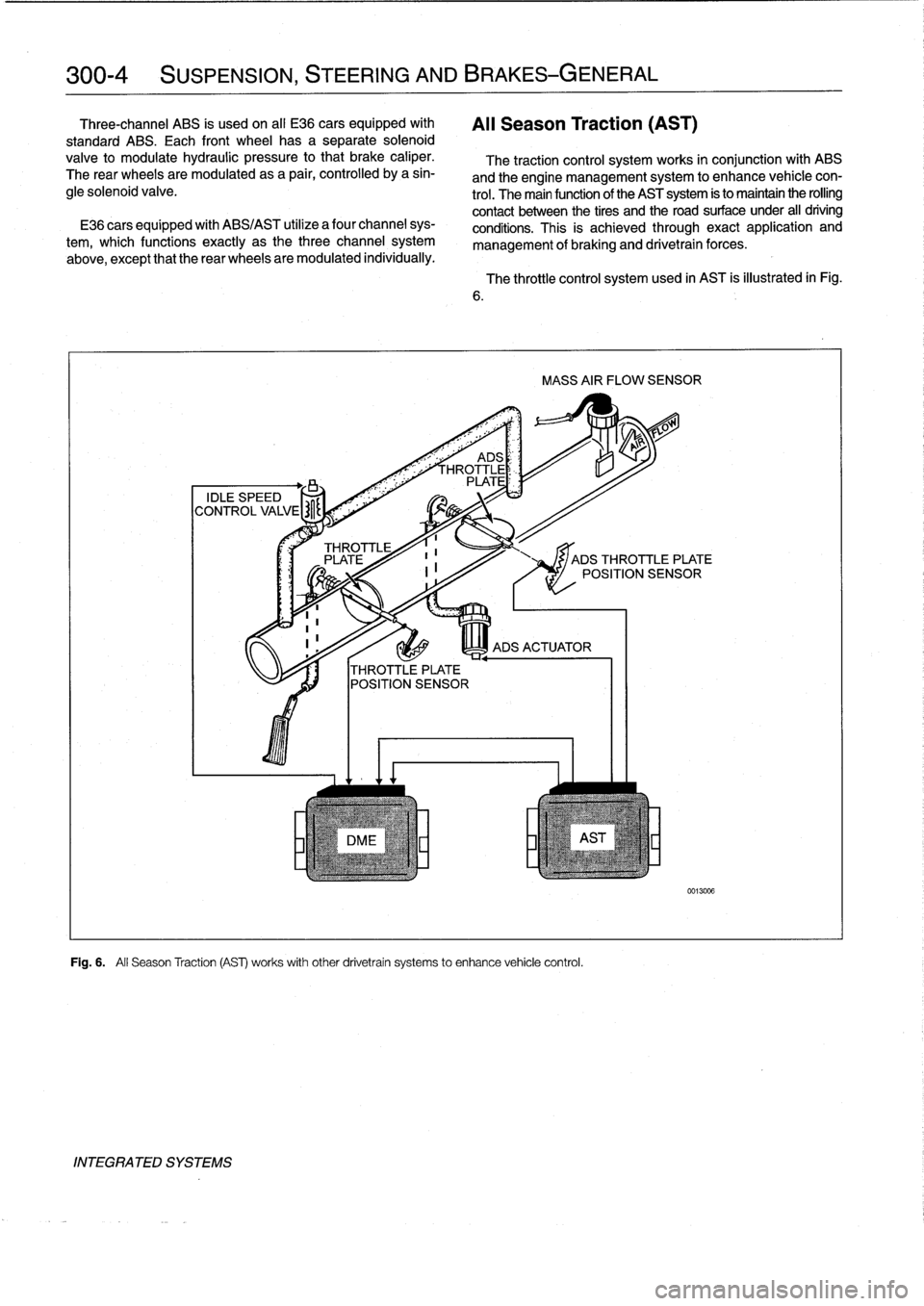
Fig
.
6
.
All
Season
Traction
(AS)
works
withother
drivetrain
systems
to
enhance
vehicle
control
.
INTEGRATED
SYSTEMS
The
throttle
control
system
used
in
AST
is
illustrated
in
Fig
.
MASS
AIR
FLOW
SENSOR
JADS
THROTTLE
PLATE
POSITION
SENSOR
0013006
Page 291 of 759
Brake
rotor,
removing
and
installing
.
.
.
.
.
.
.
.
340-7
MASTER
CYLINDER
............
.
.
.
.
.
.
.340-7
Master
cylinder,
removing
and
installing
.
...
.
340-7
GENERAL
TROUBLESHOOTING
WARNING
-
"
Although
semi-metallic
and
metallic
Brake
friction
materials
in
Brake
pads
or
shoes
no
longer
con-
tain
asbestos,
they
produce
dangerous
dust
.
"
Brake
fluid
is
poisonous,
highly
corrosive
and
dangerous
to
the
environment
Wear
safety
glasses
and
rubber
gloves
when
working
with
Brake
fluid
.
Do
not
siphonBrake
fluid
with
your
mouth
.
Immediately
clean
away
any
fluid
spilled
on
painted
surfaces
and
wash
with
water,
asBrake
fluid
will
remove
paint
.
"
Always
use
new
Brake
fluid
froma
fresh,
un-
opened
container
.
Brake
fluid
will
absorb
mois-
ture
from
the
air
.
This
canlead
to
corrosion
problems
in
the
brakingsystem,
and
will
also
low-
er
the
Brake
fluid's
boiling
point
.
Dispose
of
Brake
fluid
properly
.
"
Do
notreuse
self-locking
nuts,bolts
or
fasteners
.
They
are
designed
to
be
used
only
once
and
may
failif
reused
.
Always
replace
them
with
new
self-
locking
fasteners
.
BMW
E36
models
areequipped
with
vacuum
power-assist-
ed
four-wheel
disc
brakes
with
an
integral
Antilock
Brake
Sys-
tem
(ABS)
.
Single-pistoncalipers
act
on
solid
or
vented
front
rotors
and
solid
rear
rotors
.
A
brake
pad
wear
sensor
for
each
axle
indicates
when
brake
padsneed
replacement
.
The
dual
drum-type
parking
brakesystem
is
integrated
with
the
rear
brake
rotors
.
NOTE-
M3
models
havevented
directional
Brake
rotors
on
the
rearaxle
as
well
ason
the
front
.
340
Brakes
BRAKES
340-1
GENERAL
.
.
.
.
.
.
.........
.
.
.
..........
340-1
BRAKE
BOOSTER
.........
.
.
.
.
.
...
.
.
.
.
340-8
TROUBLESHOOTING
.......
.
......
.
...
340-1
Brake
booster,
removing
and
installing
....
.
.
340-8
PARKING
BRAKE
.
.....
.
...
.
.
.
.....
.
.
.
340-10
BLEEDING
BRAKES
.
.
.
.
.
.
.
.
..........
340-3
Parking
brake,adjusting
.
.
.
.
.
.
.
.
.
.
.....
.
340-10
Pressure
bleeding
brakes
Parking
brake
shoes,
removing
and
installing
.
340-11(except
cars
with
AST)
.
.
.
.
.
.
.
.
.
...
.
.
.
.
.340-3
Parking
Brake
cable,
replacing
.
.
.
.
.
.
.
.
.
.
.
.
340-11
BRAKE
PADS,
CALIPERS,
ANTILOCK
BRAKE
SYSTEM
(ABS)
.
.
.
.340-11
AND
ROTORS
..........
.
.......
.
.
.
.
.
.
.
340-3
ABS
System
Inspection
.
...
.
.......
.
.
.
..
340-12
Brake
pads,
replacing
............
.
.
.
.
.
.
.
340-4
ABS
wheel
speed
sensors,
replacing
.
.
.
.
..
340-12
Brake
caliper,
removing
and
installing
.
..
..
.
340-6
TABLES
a
.
Brake
System
Troubleshooting
.....
...
.
.
.....
.340-2
b
.
Brake
Rotor
Reconditioning
Specifications
.
.....
.340-7
Brakeperformance
is
mainly
affected
by
three
things
:
the
leve¡
and
condition
of
the
brake
fluid,
the
system's
abilíty
to
create
and
maintain
hydraulic
pressure,
and
the
condition
of
the
friction
components
.
Air
in
the
Brake
fluid
will
make
the
Brake
pedal
feel
spongy
during
braking
or
will
increase
the
Brake
pedalforce
required
to
stop
.
Fluid
contaminated
by
moisture
or
dirt
can
corrode
the
system
.
Inspect
the
Brake
fluid
inside
the
reservoir
.
Ifit
is
dirty
or
murky,
or
is
over
a
year
old,
the
fluid
should
be
replaced
.
Visually
check
the
hydraulic
system
startingat
the
master
cylinder
.
To
check
the
function
of
the
master
cylinder
hold
the
brake
pedal
down
hard
with
the
engine
running
.
The
pedal
should
feelsolid
and
stay
solid
.
If
the
pedal
slowly
falls
to
the
floor,
either
the
master
cylinder
is
leaking
internally,
or
fluid
is
leaking
externally
.
If
no
leaks
canbe
found,
the
master
cylin-
der
is
faulty
and
should
be
replaced
.
Check
all
Brake
fluid
lines
and
couplings
for
leaks,
kinks,
chafing
and
corrosion
.
Check
the
Brake
booster
by
pumping
the
Brake
pedal
ap-
proximately
10
times
with
the
engine
off
.
Hold
the
pedal
down
and
start
the
engine
.
The
pedal
should
fa¡¡
slightly
.
If
not,
check
for
any
visiblefaults
before
suspecting
a
faulty
brake
booster
.
Check
for
strong
vacuum
at
the
vacuum
hose
fitting
at
the
booster,
and
check
the
non-retum
valve
for
one-way
flow
.
Worn
or
contaminated
brake
pads
will
cause
poor
braking
performance
.
Oil-contaminated
or
glazed
pads
will
cause
stopping
distances
to
increase
.
Inspect
the
rotors
for
glazing,
discoloration
and
scoring
.
Steering
wheel
vibration
while
braking
at
speed
is
often
caused
by
warped
rotors,
but
can
also
be
caused
byworn
suspension
components
.
TROUBLESHOOTING
Page 385 of 759
Continuity,
checking
Short
Circuits
from
Battery
CAUTION-
Use
only
a
high
quality
digital
ohmmeter
having
high
input
impedance
when
checking
electronic
componente
.
The
internal
power
source
used
in
most
analog
(swing-need1e)
meterscan
damage
solidstate
components
.
0013239
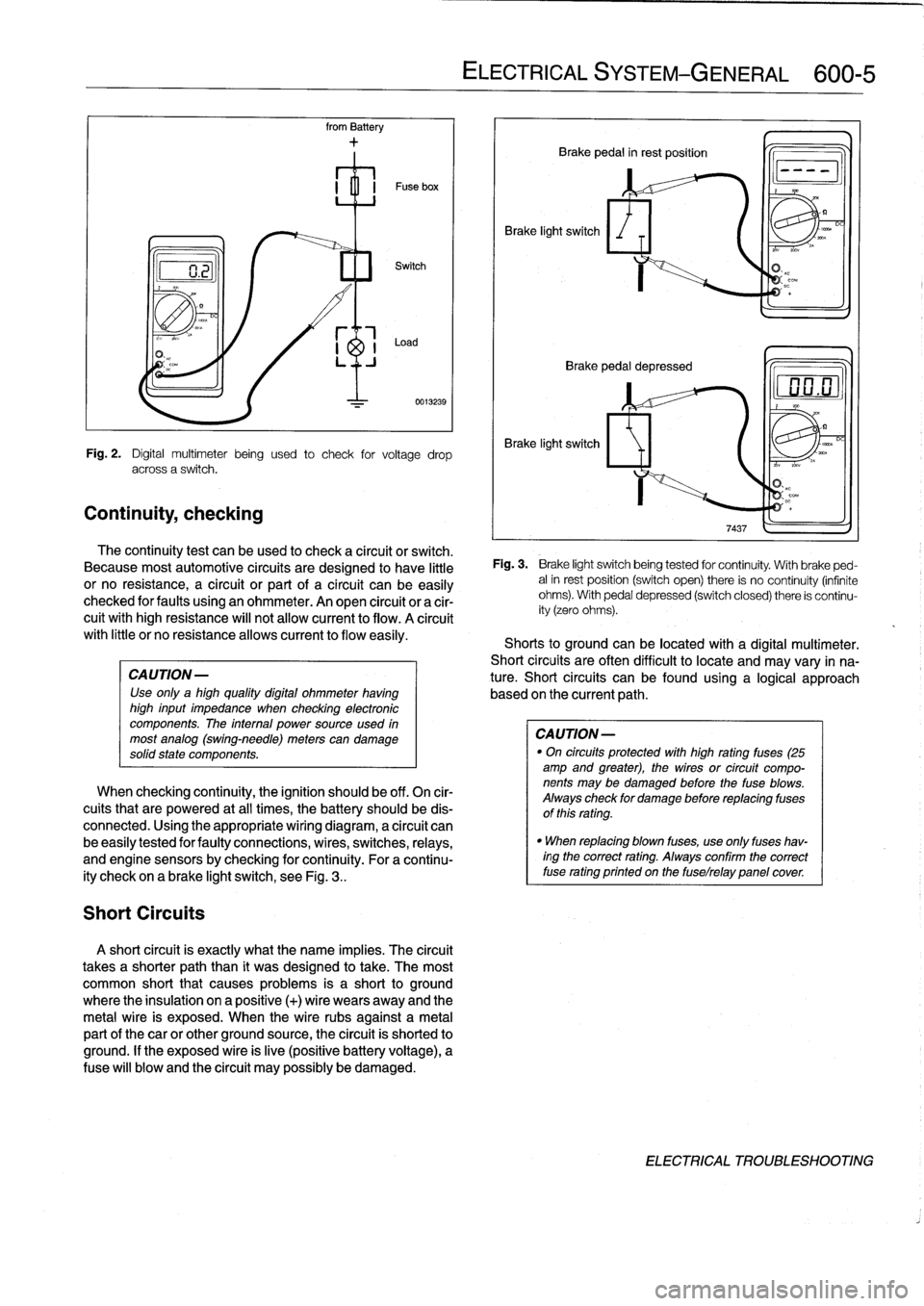
Fig
.
2
.
Digital
multimeter
being
used
to
check
for
voltage
drop
across
a
switch
.
The
continuity
test
can
beused
to
check
a
circuit
or
switch
.
Because
most
automotive
circuits
are
designed
to
have
little
or
no
resistance,
a
circuit
or
part
of
a
circuit
canbe
easily
checked
for
faults
using
an
ohmmeter
.
An
open
circuit
or
a
cir-
cuit
withhigh
resistance
will
not
allow
current
to
flow
.
A
círcuit
with
little
or
no
resistanceallows
current
to
flow
easily
.
When
checking
continuity,
the
ignition
should
be
off
.
On
cir-
cuits
that
are
powered
at
all
times,
the
battery
should
be
dis-
connected
.
Using
the
appropriate
wiring
diagram,
a
circuit
can
be
easily
tested
for
faulty
connections,
wires,
switches,
relays,
and
engine
sensorsby
checking
forcontinuity
.
For
a
continu-
ity
check
on
a
brake
light
switch,
see
Fig
.
3
..
A
short
circuit
is
exactly
what
the
narre
implies
.
The
circuit
takes
a
shorter
paththan
it
was
designed
to
take
.
The
most
common
short
that
causes
problems
is
a
short
to
ground
where
the
insulation
on
a
positive
(+)
wire
wears
away
and
the
metal
wire
is
exposed
.
When
the
wire
rubs
against
a
metal
partof
thecar
or
other
ground
source,
the
circuit
is
shorted
to
ground
.
If
the
exposed
wire
is
live
(positive
battery
voltage),
a
Puse
will
blow
and
the
circuit
may
possibly
be
damaged
.
ELECTRICAL
SYSTEM
-
GENERAL
600-
5
Brake
light
switch
Brake
pedal
in
rest
position
Q
Brake
pedal
depressed
Brake
light
switch
Fig
.
3
.
Brake
light
switchbeing
tested
for
continuity
.
With
brake
ped-
alin
rest
position
(switch
open)
there
is
no
continuity
(infinite
ohms)
.
With
pedal
depressed
(switch
closed)
there
is
continu-
ity
(zero
ohms)
.
Shorts
to
groundcanbe
located
with
a
digital
multimeter
.
Short
circuits
are
often
difficult
to
locate
and
may
vary
in
na-
ture
.
Short
circuits
can
befound
using
a
logical
approach
based
onthe
current
path
.
CAUTION
-
"
On
circuits
protected
with
high
rating
fuses
(25
amp
and
greater),
the
wires
or
circuit
compo-
nents
may
be
damaged
before
the
fuse
blows
.
Always
check
for
damage
before
replacing
fuses
of
this
rating
.
"
When
replacing
blown
fuses,
use
only
fuses
hav-
ingthe
correct
rating
.
Always
confirm
the
correct
fuse
rating
printed
on
the
fuselrelay
panelcover
DC
ELECTRICAL
TROUBLESHOOTING
Page 388 of 759
610-2
ELECTRICAL
COMPONENT
LOCATIONS
Fuses
number47
and
50are
mounted
on
the
left
side
splice
panel
.
Refer
lo
Fig
.
5
.
Fuse48
is
mounted
on
the
auxiliary
relay
panel
.
Refer
to
Fig
.
3
.
Fuse
49
is
mounted
in
the
right
side
of
the
luggage
compart-
ment
behind
the
trim
cover
.
Relay
Positions
Mounted
in
the
left-hand
rear
comer
of
the
engine
compart-
ment,
the
power
distribution
box
contains
46
(uses
and
15
re-
lay
positions
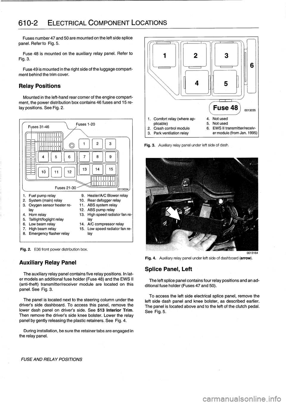
.
See
Fig
.
2
.
Fuses31-46
-
Er
a
&QT
MM
~
Fig
.
2
.
E36
front
power
distribution
box
.
FUSE
AND
RELAY
POSITIONS
Fuses1-20
13
EL1
5
]
mmmmmmmmmm
Fuses
21-30
--
0013034)
1
.
Fuel
pump
relay
9
.
Heater/A/C
Blower
relay
2
.
System
(main)
relay
10
.
Rear
defogger
relay
3
.
Oxygen
sensorheater
re-
11
.
ABS
system
relay
lay
12
.
ABS
pump
relay
4
.
Horn
relay
13
.
High
speed
radiator
fan
re-
5
.
Taillight/foglight
relay
]ay
6
.
Low
beam
relay
14
.
A/C
compressor
relay
7
.
High
beam
relay
15
.
Low
speed
radiator
fan
re-
8
.
Emergency
flasherrelay
¡ay
Auxiliary
Relay
Panel
The
auxiliary
relay
panel
contains
five
relay
positions
.
In
lat-
er
modeis
an
additional
fuse
holder
(Fuse48)
and
the
EWS
II
(anti-theft)
transmitter/receiver
module
are
located
on
this
panel
.
See
Fig
.
3
.
The
panel
is
located
nextto
the
steering
column
under
the
driver's
side
dashboard
.
To
access
this
panel,
remove
the
pwer
dash
panel
on
driver's
side
.
See513
Interior
Trim
.
Then
remove
the
driver's
side
knee
bolster
.
Lower
the
relay
panel
by
gently
releasing
the
plastic
retainers
.
See
Fig
.
4
.
During
installation,
be
sure
the
retainer
tabs
are
engaged
in
the
relay
panel
.
Splice
Panel,
Left
3
¡ni
Fig
.
3
.
Auxiliary
relay
panel
under
left
side
of
dash
.
Fuse
48)
0013035
1
.
Comfort
relay
(where
ap-
4
.
Not
used
plicable)
5
.
Not
used
2
.
Crash
control
module
6
.
EWS
II
transmitter/receiv-
3
.
Park
ventilation
relay
er
module
(from
Jan
.
1995)
0013164
Fig
.
4
.
Auxiliary
relay
panel
under
left
sideof
dashboard
(arrow)
.
The
left
splice
panel
contains
four
relay
positions
and
an
ad-
ditional
fuse
holder
(Fuses
47
and
50)
.
To
access
the
left
side
electrical
splice
panel,
remove
the
left
side
dash
panel
and
knee
bolster,
as
described
earlier
.
The
panel
is
located
above
and
lo
the
left
of
the
clutch
pedal
.
See
Fig
.
5
.
Page 391 of 759
1
.
Heater
valves
2
.
ABS
pedal
travel
sensor3
.
ABS
pump
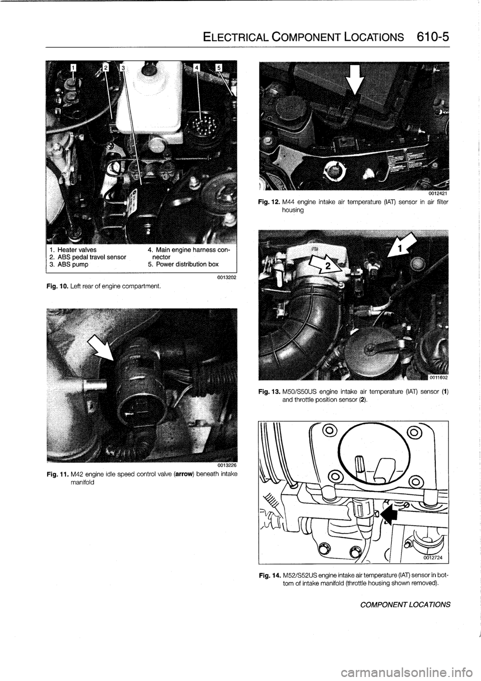
Fig
.
10
.
Left
rear
of
engine
compartment
.
4
.
Main
engineharness
con-
nector
5
.
Power
distribution
box
ELECTRICAL
COMPONENT
LOCATIONS
610-5
0013202
0013226
Fig
.
11
.
M42
engine
idie
speed
control
valve
(arrow)
beneath
intake
manifold
0012421
Fig
.
12
.
M44
engine
intake
air
temperature
(¡Al)
sensor
in
air
filter
housing
Fig
.
13
.
M50/S50U
S
engine
intake
air
temperature
(IAT)
sensor
(1)
and
throttle
position
sensor
(2)
.
301180
0012724
Fig
.
14
.
M52/S52U
S
engine
intake
air
temperature
(IAT)
sensor
in
bot-
tom
of
intake
manifold
(throttle
housing
shown
removed)
.
COMPONENT
LOCATIONS
Page 393 of 759
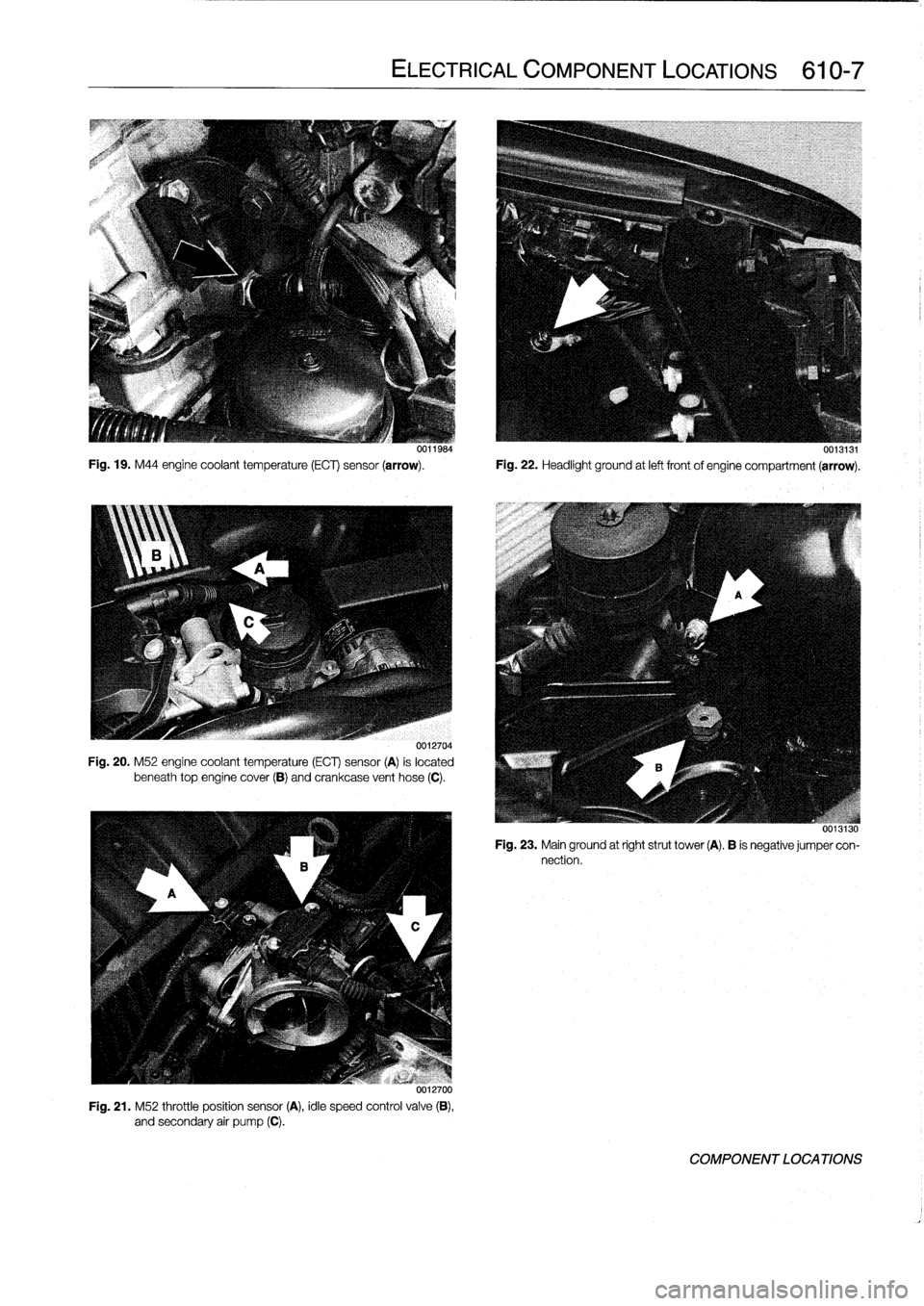
Fig
.
19
.
M44
engine
coolant
temperature
(ECT)
sensor
(arrow)
.
Fig
.
22
.
Headlight
ground
at
left
frontof
engine
compartment
(arrow)
.
0012704
Fig
.
20
.
M52
engine
coolant
temperature
(ECT)
sensor
(A)
is
located
beneath
top
enginecover
(B)
and
crankcase
vent
hose
(C)
.
uu12700
Fig
.
21
.
M52
throttle
position
sensor
(A),
idle
speed
control
valve
(B),
and
secondary
air
pump
(C)
.
ELECTRICAL
COMPONENT
LOCATIONS
610-7
00119s4
0013131
uvijijo
Fig
.
23
.
Mainground
at
right
strut
tower
(A)
.
B
is
negative
jumper
con-
nection
.
COMPONENT
LOCA
TIONS
Page 396 of 759
610-10
ELECTRICAL
COMPONENT
LOCATIONS
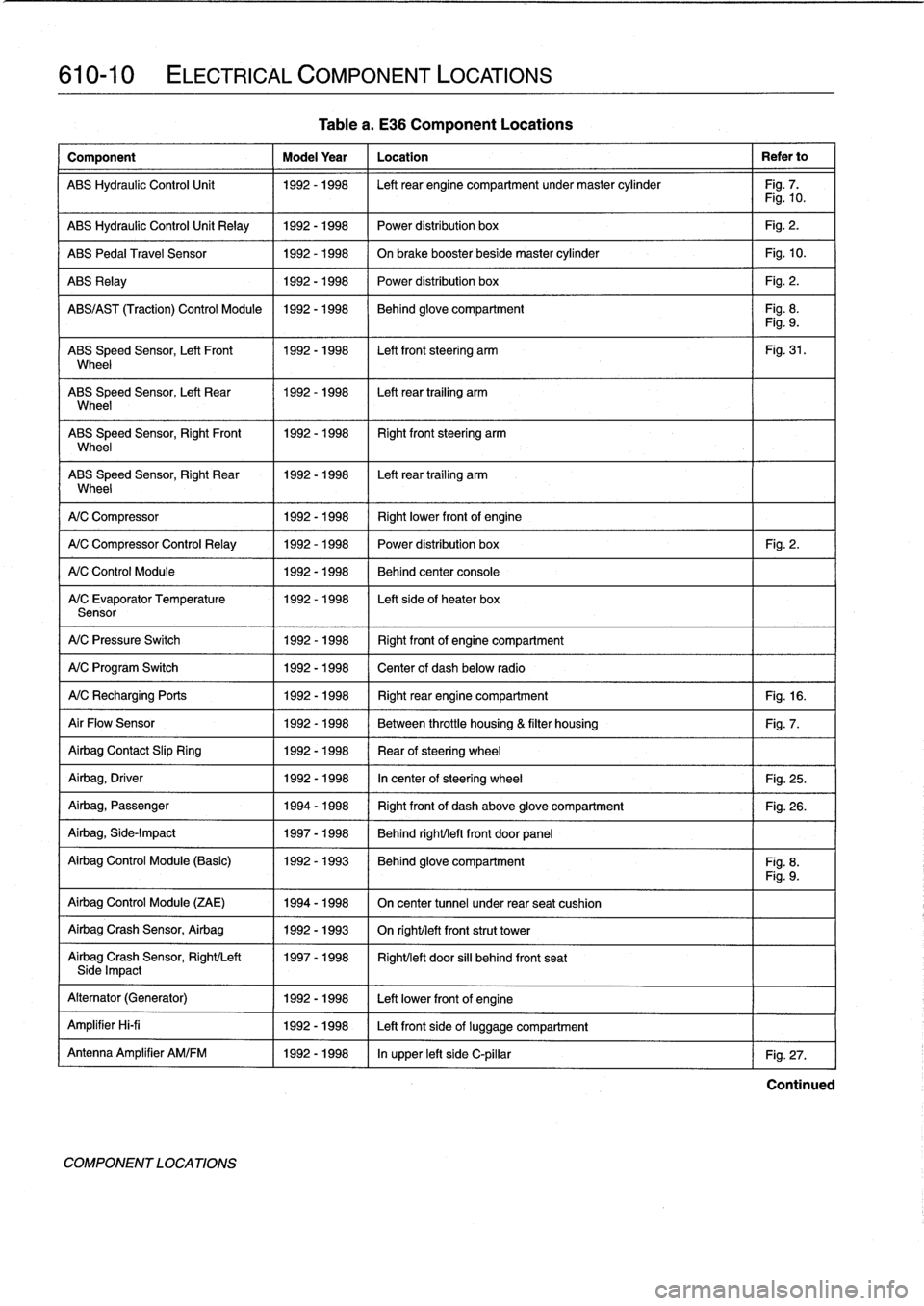
Component
Model
Year
Location
Refer
to
ABS
Hydraulic
Control
Unit
1992-1998
Left
rear
engine
compartment
undermaster
cylinder
Fig
.
7
.
Fig
.
10
.
ABS
Hydraulic
Control
Unit
Relay
1992-1998
Power
distribution
box
Fig
.
2
.
ABS
Pedal
Travel
Sensor
1992-1998
On
brake
booster
beside
master
cylinder
Fig
.
10
.
ABS
Relay
1992-1998
Power
distribution
box
Fig
.
2
.
ABS/AS
T
(Traction)
Control
Module
1992-1998
Behind
glove
compartment
Fig
.
8
.
Fig
.
9
.
ABS
Speed
Sensor,
Left
Front
1992-1998
Left
front
steering
arm
Fig
.
31
.
Wheel
ABS
Speed
Sensor,
Left
Rear
1992-1998
Left
rear
trailing
arm
Wheel
ABS
Speed
Sensor,
RightFront
11992-1998
Right
front
steering
arm
Wheel
ABS
Speed
Sensor,
Right
Rear
1992-1998
I
Left
rear
trailing
arm
Wheel
1
A/C
Compressor
1
1992-1998
(
Rightlower
frontof
engine
A/C
Compressor
Control
Relay
1
1992-1998
1992-1998
1992-1998
A/C
Control
Module
A/C
Evaporator
Temperature
Sensor
A/C
Pressure
Switch
1992-1998
Right
frontof
engine
compartment
A/C
Program
Switch
1992-1998
Center
of
dash
below
radio
A/CRecharging
Ports
1992-1998
Right
rear
engine
compartment
Fig
.
16
.
Air
Flow
Sensor
1992-1998
Between
throttle
housing
&
filter
housing
Fig
.
7
.
Airbag
Contact
Slip
Ring
1992-1998
Rear
ofsteering
wheel
Airbag,
Driver
1992-1998
In
center
of
steering
wheel
Fig
.
25
.
Airbag,
Passenger
1994-1998
Right
front
of
dash
above
glove
compartment
Fig
.
26
.
Airbag,
Side-Impact
1997-1998
Behind
right/left
front
door
panel
Airbag
Control
Module
(Basic)
1992-1993
Behind
glove
compartment
Fig
.
8
.
Fig
.
9
.
Airbag
Control
Module
(ZAE)
1994-1998
On
center
tunnel
under
rear
seat
cushion
Airbag
Crash
Sensor,
Airbag
1992-1993
On
righUleft
front
strut
tower
Airbag
Crash
Sensor,
Right/Left
1997-1998
Right/left
door
si¡¡
behind
front
seatSide
Impact
Alternator
(Generator)
1992-1998
Left
lowerfront
of
engine
Amplifier
Hi-fi
1992-1998
Left
front
side
of
luggage
compartment
Antenna
Amplifier
AM/FM
1992-1998
In
upper
left
side
C-pillar
Fig
.
27
.
COMPONENT
LOCA
TIONS
Table
a
.
E36
Component
Locations
Power
distribution
box
Fig
.
2
.
Behind
center
console
Left
sideof
heater
box
Continued
Page 397 of 759
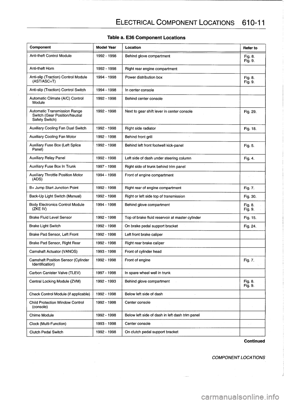
Table
a
.
E36
Component
Locations
Component
Model
Year
Location
Refer
to
Anti-theft
Control
Module
1992-1998
Behind
glove
compartment
Fig
.
8
.
Fig
.
9
.
Anti-theft
Horn
1
1992-1998
1
Right
rear
engine
compartment
Anti-slip
(Traction)
Control
Module
1994-1998
Power
distribution
box
Fig
.
8
.
(AST/ASC+T)
Fig
.
9
.
Anti-slip
(Traction)
Control
Switch
1994-1998
In
center
console
Automatic
Climate
(A/C)
Control
1992-1998
Behind
center
console
Module
AutomaticTransmission
Range
1992-1998
~
Next
to
gear
shift
lever
in
center
console
Fig
.
29
.
Switch
(Gear
Position/Neutral
Safety
Switch)
Auxiliary
Cooling
Fan
Dual
Switch
1992-1998
Right
side
radiator
1
Fig
.
18
.
Auxiliary
Cooling
Fan
Motor
1992-1998
Behind
front
grill
Auxiliary
Fuse
Box
(Left
Splice
1992-1998
I
Behind
left
front
footwell
kick-panel
Panel)
Auxiliary
RelayPanel
1
1992-1998
1
Left
side
of
dash
under
steering
column
Auxiliary
Fuse
Box
In
Trunk
1
1997-1998
1
Right
sideof
trunk
behind
trim
panel
AuADSry
ThrottlePosition
Motor
11994-1998
Front
of
engine
compartment
B+
Jump
Start
Junction
Point
1992-1998
Right
rear
of
engine
compartment
Fig
.
7
.
Back-Up
Light
Switch
(Manual)
1992-1998
Right
or
left
side
top
of
transmission
Fig
.
30
.
Body
Electronics
Control
Module
1994-1998
Behindglove
compartment
Fig
.
8
.
(ZKE
IV)
Fig
.
9
.
Brake
Fluid
Level
Sensor
1992-1998
Top
of
brake
fluid
reservoir
at
master
cylinder
Fig
.
15
.
Brake
Light
Switch
1
1992-1998
1
On
brake
pedal
supportbracket
Brake
Pad
Sensor,
Left
Front
1
1992-1998
1
Left
front
brake
caliper
Brake
Pad
Sensor,
Right
Rear
1992-1998
Right
rear
brake
caliper
Camshaft
Actuator
(VANOS)
1993-1998
Front
of
cylinder
head
Camshaft
Position
Sensor
(Cylinder
1992-1998
Front
of
engine
Identification)
Carbon
Canister
Valve
(TLEV)
1
1997-1998
1
In
sparewheel
well
in
trunk
ELECTRICAL
COMPONENT
LOCATIONS
610-11
Fig
.
5
.
Fig
.
4
.
Fig
.
24
.
Fig
.
7
.
Central
Locking
Module
(ZVM)
11992-1993
1
Behindglove
compartment
I
Fig
.
8
.
Fig
.
9
.
Check
Control
Module
(if
applicable)
1
1992
-
1998
1
Below
left
side
of
dash
Child
Protection
Window
Control
1992-1998
Center
console
(console)
Chime
Module
1992-1998
Below
left
side
of
dash
inleft
dash
trim
panel
Clock
(Multi-Function)
1993-1998
Center
console
Clutch
Pedal
Switch
1992-1998
On
clutch
pedal
support
bracket
Continued
COMPONENT
LOCATIONS
Page 398 of 759
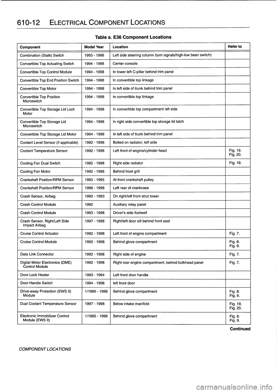
610-12
ELECTRICAL
COMPONENT
LOCATIONS
Table
a
.
E36
Component
Locations
Component
Model
Year
Location
Refer
to
Combination
(Stalk)
Switch
1993-1998
Left
sidesteering
column
(turn
signals/high-low
bean
switch)
Convertible
Top
ActuatingSwitch
1994-1998
Center
console
Convertible
Top
Control
Module
1994-1998
In
lower
left
C-pillar
behind
trim
panel
Convertible
TopEnd
Position
Switch
1994-1998
In
convertible
top
linkage
Convertible
Top
Motor
1994-1998
In
left
sideof
trunk
behind
trim
panel
Convertible
Top
Position
1994-1998
In
convertible
top
linkage
Microswitch
Convertible
Top
Storage
Lid
Lock
1994-1998
In
convertible
top
compartment
left
side
Motor
Convertible
Top
Storage
Lid
1994-1998
Inright
side
convertible
top
storage
lid
latch
Microswitch
Convertible
Top
Storage
Lid
Motor
1994-1998
In
left
side
of
trunk
behind
trim
panel
Coolant
Leve¡
Sensor
(if
applicable)
1992-1998
Bolted
on
radiator,
left
side
Coolant
Temperature
Sensor
1992-1998
Left
front
of
engine/cylinder
head
Fig
.
19
.
Fig
.
20
.
Cooling
Fan
Dual
Switch
1992-1998
Right
side
radiator
Fig
.
18
.
Cooling
Fan
Motor
1992-1998
Behind
front
grill
Crankshaft
Position/RPM
Sensor
1992-1995
At
front
crankshaft
pulley
Crankshaft
Position/RPM
Sensor
1996-1998
Left
rearof
crankcase
Crash
Sensor,
Airbag
1992-1993
On
right/left
frontstrut
tower
Crash
Control
Module
1992
Auxiliary
relay
panel
Crash
Control
Module
1993-1998
Driver's
side
footwell
Crash
Sensor,
Right/Left
Side
1997-1998
Right/left
door
sill
behind
front
seat
Impact
Airbag
Cruise
Control
Actuator
1992-1998
Left
front
of
engine
compartment
Fig
.
7
.
Cruise
Control
Module
1992-1998
Behind
glove
compartment
Fig
.
8
.
Fig
.
9
.
Data
Link
Connector
1992-1998
Right
sideof
engine
Fig
.
7
.
Digital
Motor
Electronics
(DME)
1992-1998
Right
rear
engine
compartment,
behind
bulkhead
panel
Fig
.
7
.
Control
Module
DoorLock
Heater
1993-1994
Left
front
doorhandle
DoorHandle
Switch
1994-1998
left
front
door
Drive-away
Protection
(EWS
II)
1/1995
-
1998
Behind
glove
compartment
Fig
.
8
.
Module
Fig
.
9
.
Dual
Coolant
Temperature
Sensor
1997-1998
Below
intake
manifold
Fig
.
19
.
COMPONENT
LOCATIONS
Fig
.
20
.
Electronic
Immobilizer
Control
(
1/1995-1998
~
Behind
glove
compartment
Fig
.
8
.
Module
(EWS
II)
Fig
.
9
.
Continued