trunk BMW 318i 1995 E36 User Guide
[x] Cancel search | Manufacturer: BMW, Model Year: 1995, Model line: 318i, Model: BMW 318i 1995 E36Pages: 759
Page 304 of 759
400-2
BODY-GENERAL
4-door
Sedan
Coupe
-
saas3
.7""
351
/
37
.3
O
I
x
`-193
267
o
oa
'3281
model
"M3
model
Convertible
BODYASSEMBLY
55
ass
.e
iss
""
-
66
.9
-
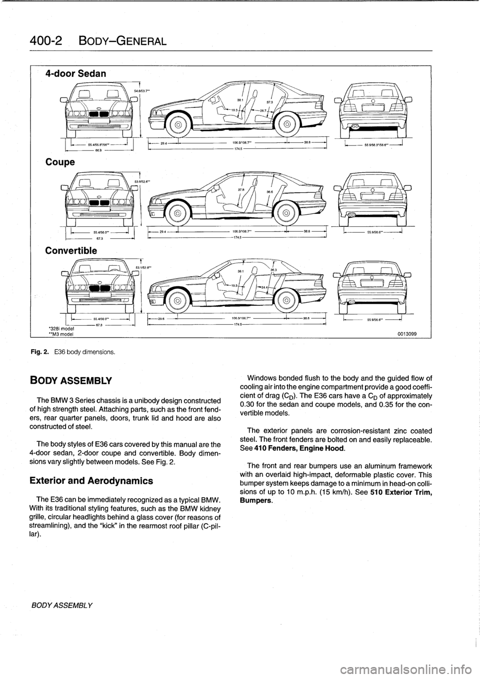
Fig
.
2
.
E36
body
dimensíons
.
BODY
ASSEMBLY
29
.4
29
4
The
BMW
3
Series
chassis
is
a
unibodydesign
constructed
ofhigh
strength
steel
.
Attaching
parts,
suchas
the
front
fend-
ers,
rear
quarter
panels,
doors,
trunk
lid
and
hood
are
also
constructed
of
steel
.
706
.31108
.7"
I
38
.5
174
.5
174
.5
O
oo
196
.3/106
.7'
"
35_5
1.
.
55
.9,566
".
106
.3/196
.7""
i.
358
-1745-
55
9/56
3'/56
6"
-
J
0013099
Windows
bonded
flush
to
the
body
and
the
guided
flow
of
cooling
air
into
the
engine
compartment
provide
a
good
coeffi-
cient
of
drag(CD)
.
TheE36
cars
have
a
CD
of
approximately
0
.30for
the
sedan
and
coupe
models,
and
0
.35
for
the
con-
vertible
models
:
The
exterior
panels
are
corrosion-resistant
zinc
coated
steel
.
The
front
fenders
are
bolted
on
and
easily
replaceabie
.
The
body
styles
of
E36
cars
coveredby
this
manual
arethe
See410
Fenders,
Engine
Hood
.
4-door
sedan,
2-door
coupe
and
convertible
.
Body
dimen-
sions
vary
slightly
betweenmodels
.
See
Fig
.
2
.
The
front
and
rear
bumpers
use
an
aluminum
framework
with
an
overlaid
high-impact,
deformable
plastic
cover
.
This
Exterior
and
Aerodynamics
bumper
system
keeps
damage
to
a
minimum
in
head-on
colli-
sions
of
up
to
10
m
.p
.h
.
(15
km/h)
.
See
510
Exterior
Trim,
TheE36
can
be
immediatelyrecognized
asa
typical
BMW
.
Bumpers
.
With
its
traditionalstyling
features,
suchas
the
BMW
kidney
grille,
circular
headlights
behind
a
glass
cover
(for
reasons
of
streamliníng),
and
the
"kick"
in
the
rearmost
roof
pillar
(C-pil-
lar)
.
Page 307 of 759
Ambient
temperaturelclock
MÍM
Aa
.Mi}rm
-Mil"
IMua~naa~u~itacar
"
za
.~
Central
Body
Electronics
0013028
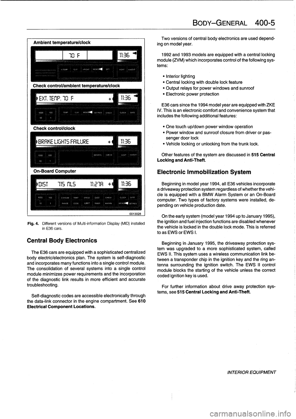
Fig
.
4
.
Different
versionsof
Multi-information
Display(MID)
installed
in
E36
cars
.
The
E36
cars
are
equipped
with
a
sophisticated
centralized
body
electric/electronics
plan
.
The
system
is
self-diagnostic
and
incorporates
many
functions
into
a
single
control
module
.
The
consolidation
of
several
systems
into
a
single
control
module
minimizes
power
requirements
and
the
incorporation
of
the
diagnostic
link
results
in
more
efficient
and
accurate
troubleshooting
.
Self-diagnostic
codes
are
accessible
electronically
through
the
data-link
connector
in
the
engine
compartment
.
See610
Electrical
Component
Locations
.
BODY-GENERAL
400-
5
Two
versions
of
central
body
electronics
are
used
depend-
ing
on
model
year
.
1992
and
1993
models
are
equipped
with
a
central
locking
module
(ZVM)
which
incorporates
control
of
the
following
sys-
tems
:
"Interiorlighting
"
Central
locking
with
double
lock
feature
"
Output
relays
for
powerwindows
and
sunroof
"
Electronic
power
protection
E36
cars
since
the
1994
model
year
are
equipped
with
ZKE
IV
.
This
is
an
electronic
comfort
and
convenience
system
that
includes
the
following
additional
features
:
"
One
touch
up/down
power
window
operation
"
Power
window
and
sunroof
closure
from
driver
or
pas-
sengerdoor
lock
"
Vehicle
locking
or
unlocking
from
the
trunk
lock
.
Other
features
of
the
system
are
discussed
in
515
Central
Locking
and
Anti-Theft
.
Electronic
Immobilization
System
Beginning
in
model
year
1994,
all
E36
vehicles
incorporate
adriveaway
protection
system
regardless
of
whether
the
vehi-
cle
is
equipped
with
a
BMW
Alarm
System
or
an
On-Board
computer
.
Two
types
of
factory
systems
were
installed,
de-
pending
on
vehicle
production
date
.
On
the
early
system
(model
year
1994
up
to
January
1995),
the
ignition
and
fuel
injection
functions
are
disabled
whenever
the
vehicle
is
locked
in
the
double
lock
mode
.
This
is
referred
lo
as
EWS
or
EWS
I
.
Beginning
in
January
1995,
the
driveaway
protection
sys-
tem
was
upgraded
to
a
more
sophisticated
system,
called
EWS
II
.
This
system
uses
a
wireless
communication
link
be-
tween
a
transponder
chip
in
the
ignition
keyand
the
ring
an-
tenna
surrounding
the
ignition
switch
.
The
EWS
II
control
module
blocksthe
starting
of
the
vehicle
unlessthe
correct
coded
ignition
key
is
used
.
For
further
information
about
drive
away
protection
sys-
tems,
see
515
Central
Locking
and
Anti-Theft
.
INTERIOR
EQUIPMENT
Page 321 of 759
GENERAL
This
repair
group
covers
trunk
lid
removal
and
installation
.
Also
inciuded
here
arereplacement
procedures
for
the
gas-
charged
support
struts
that
hold
the
trunk
lid
in
the
up
position
.
NOTE
-
The
body
ís
painted
at
the
factory
after
assembly
.
Re-
alignment
of
body
panels
may
expose
unpainted
metal
.
Paint
all
exposed
metal
once
the
work
is
complete
.
TRUNK
LID
Trunk
lid,
removing
and
installing
1
.
Raise
trunk
lid
.
Open
tool
kit
and
remove
screws
at-
taching
tool
kit
lo
trunk
lid
.
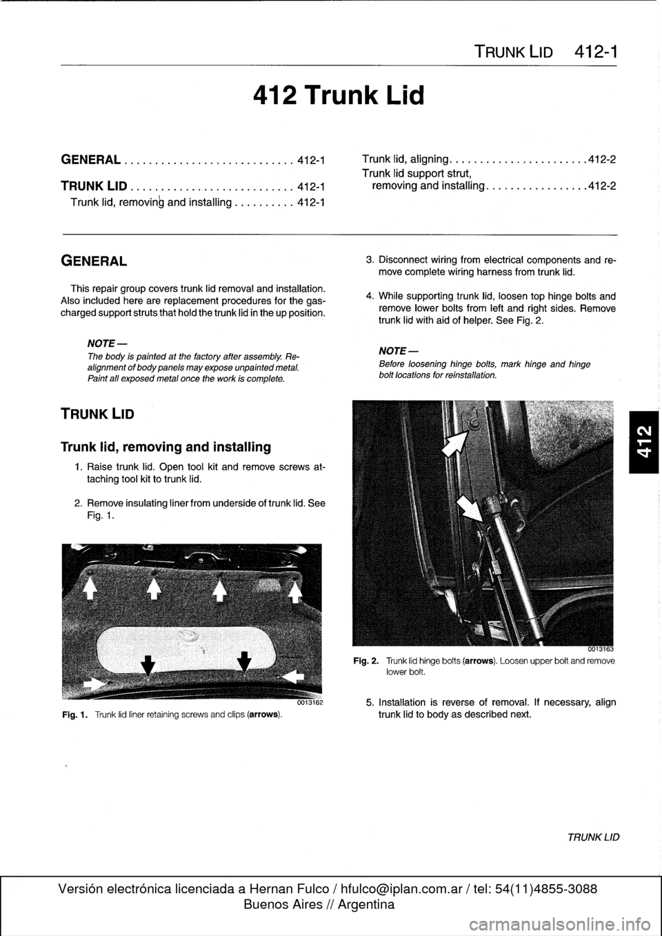
2
.
Remove
insulating
liner
from
underside
of
trunk
lid
.
See
Fig
.
1
.
412
Trunk
Lid
TRUNK
LID
412-1
GENERAL
............
.
...
.
.....
.
...
.
.
412-1
Trunk
lid,
aligning
.
.
.
.
.
.....
.
...
.
.
.
.
.
.
.
..
412-2
Trunk
lid
support
strut,
TRUNK
LID
.
.
.
............
.
.
.
...
.
.
.
.
.
.
412-1
removing
and
installing
..
.
.
.
.
.
.
.
.
.
...
.
.
.
412-2
Trunk
lid,
removinb
and
installing
......
.
.
.
.
412-1
3
.
Disconnect
wiring
from
electrical
components
and
re-
move
complete
wiring
harness
from
trunk
lid
.
4
.
While
supporting
trunk
lid,
loosen
top
hinge
bolts
and
remove
lower
bolts
from
left
and
right
sides
.
Remove
trunk
lid
with`aid
of
helper
.
See
Fig
.
2
.
NOTE-
Before
loosening
hinge
bolts,
mark
hinge
and
hinge
bolt
locations
for
reínstallation
.
0013163
Fig
.
2
.
Trunk
lid
hinge
bolts
(arrows)
.
Loosen
upper
bolt
and
remove
lower
bolt
.
0013162
5
.
Installation
is
reverse
of
removal
.
If
necessary,
align
Fig
.
1
.
Trunk
lid
liner
retaining
screws
and
clips
(arrows)
.
trunk
lid
to
body
as
described
next
.
TRUNK
LID
Page 322 of 759
412-2
TRUNK
LID
Trunk
lid,
aligning
1.
Raise
trunk
lid
.
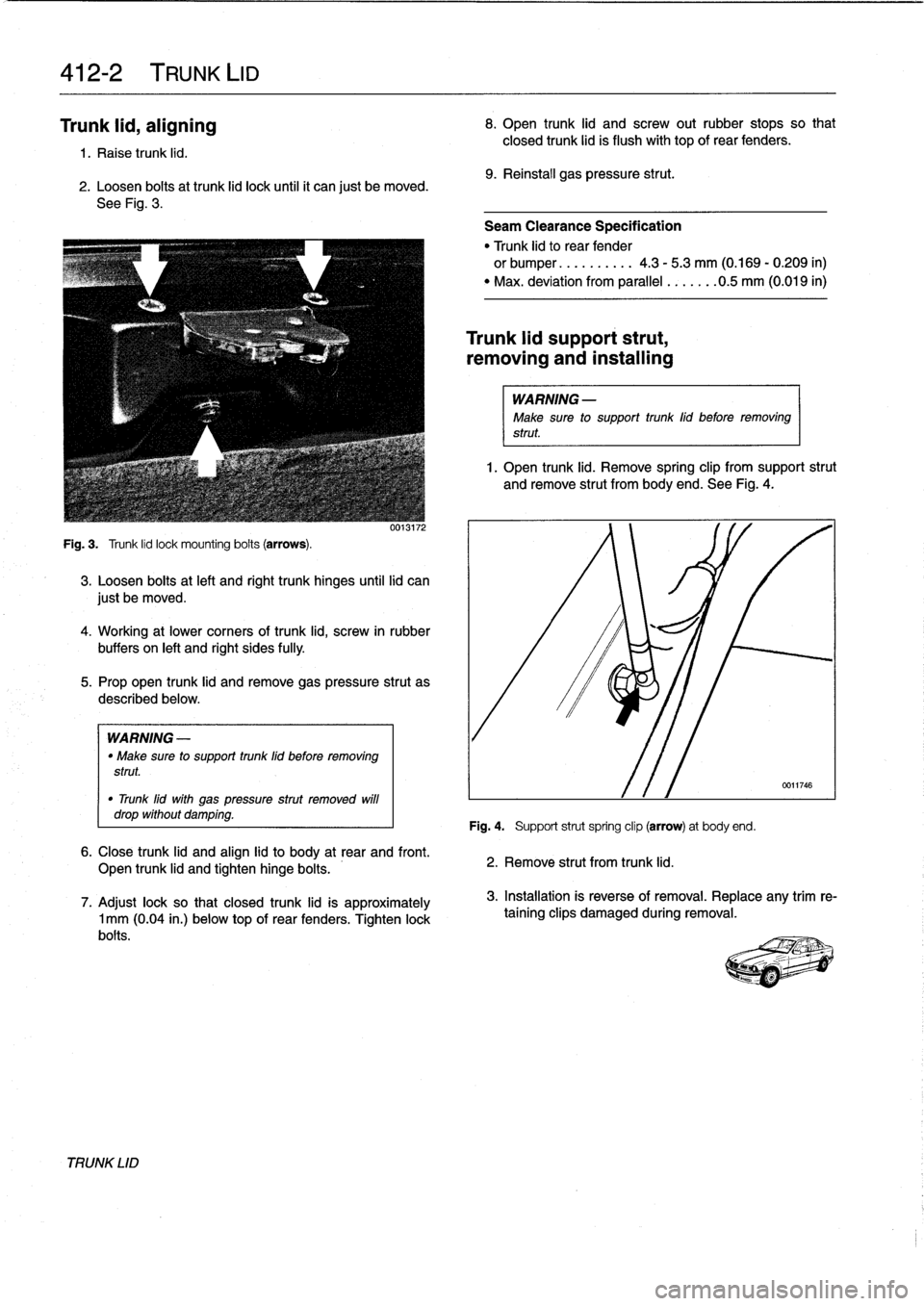
2
.
Loosen
boits
at
trunk
lid
lock
until
it
can
just
be
moved
.
See
Fig
.
3
.
Fig
.
3
.
Trunk
lid
lock
mounting
boits
(arrows)
.
0013172
3
.
Loosen
bolis
at
left
and
right
trunk
hinges
until
lid
can
just
be
moved
.
4
.
Working
at
lower
comers
of
trunk
lid,
screw
in
rubber
buffers
on
left
and
right
sides
fully
.
5
.
Prop
open
trunk
lid
and
remove
gas
pressure
strut
as
described
below
.
WARNING
-
"
Make
sure
to
support
trunk
lid
before
removing
strut
.
"
Trunk
lid
with
gas
pressure
strut
removed
will
drop
without
damping
.
6
.
Close
trunk
lid
and
align
lid
to
body
at
rear
and
front
.
Open
trunk
lid
and
tighten
hinge
bolis
.
7
.
Adjust
lock
so
that
closed
trunk
lid
is
approximately
1
mm
(0
.04
in
.)
belowtop
of
rear
fenders
.
Tighten
lock
bolts
.
TRUNK
LID
8
.
Open
trunk
lid
and
screw
outrubber
stops
so
that
closed
trunk
lid
is
flush
with
top
of
rear
fenders
.
9
.
Reinstall
gas
pressure
strut
.
Seam
Clearance
Specification
"
Trunk
lid
to
rear
fender
or
bumper
..........
4
.3
-
5
.3
mm
(0
.169
-
0
.209
in)
"
Max
.
deviation
from
parallel
.......
0
.5
mm
(0
.019
in)
Trunk
lid
support
strut,
removing
and
installing
WARNING
-
Make
sure
to
support
trunk
lid
before
removing
strut
1
.
Open
trunk
lid
.
Remove
spring
clip
from
support
strut
and
remove
strut
from
body
end
.
See
Fig
.
4
.
Fig
.
4
.
Support
strut
spring
clip
(arrow)
at
body
end
.
2
.
Remove
strut
from
trunk
lid
.
3
.
Installation
is
reverse
of
removal
.
Replace
any
trim
re-
taining
clips
damaged
during
removal
.
Page 354 of 759
515-6
CENTRAL
LOCKING
AND
ANTI-THEFT
6
.
Remove
door
handle
assembly
from
inside
door
.
7
.
Installation
is
reverse
of
removal
.
Keep
in
mindthe
fol-
lowing
:
"
Make
sure
rubber
seal
for
handle
is
correctly
posi-
tionedbefore
tightening
mounting
fasteners
.
"
Install
exterior
trim
piece
and
then
use
a
hooked
toolto
pull
locking
plate
into
locked
position
.
Make
sure
door
handle
trim
contacts
body
evenly
before
lockingtrim
in
place
.
"
Reconnect
all
harness
connectors
(including
power
window
motor)before
installing
door
panel
.
"
Secure
wire
harnesses
withwire
ties
.
"
Adjust
windowas
described
in
512
Door
Windows
.
Tightening
Torque
"
Rear
door
handle
mounting
screws
..
10
Nm
(89
in-lb)
NOTE
If
the
striker
backup
plate
fafls
into
the
body
cavlty,
it
can
be
retrieved
after
removing
the
inside
trim
from
the
B-pillar
(door-post
pillar)
.
Tightening
Torque
"
Striker
plate
to
body
pillar
..........
28
Nm
(20
ft-lb)
LOCKING
ACTUATORS
Door
Locking
Actuator
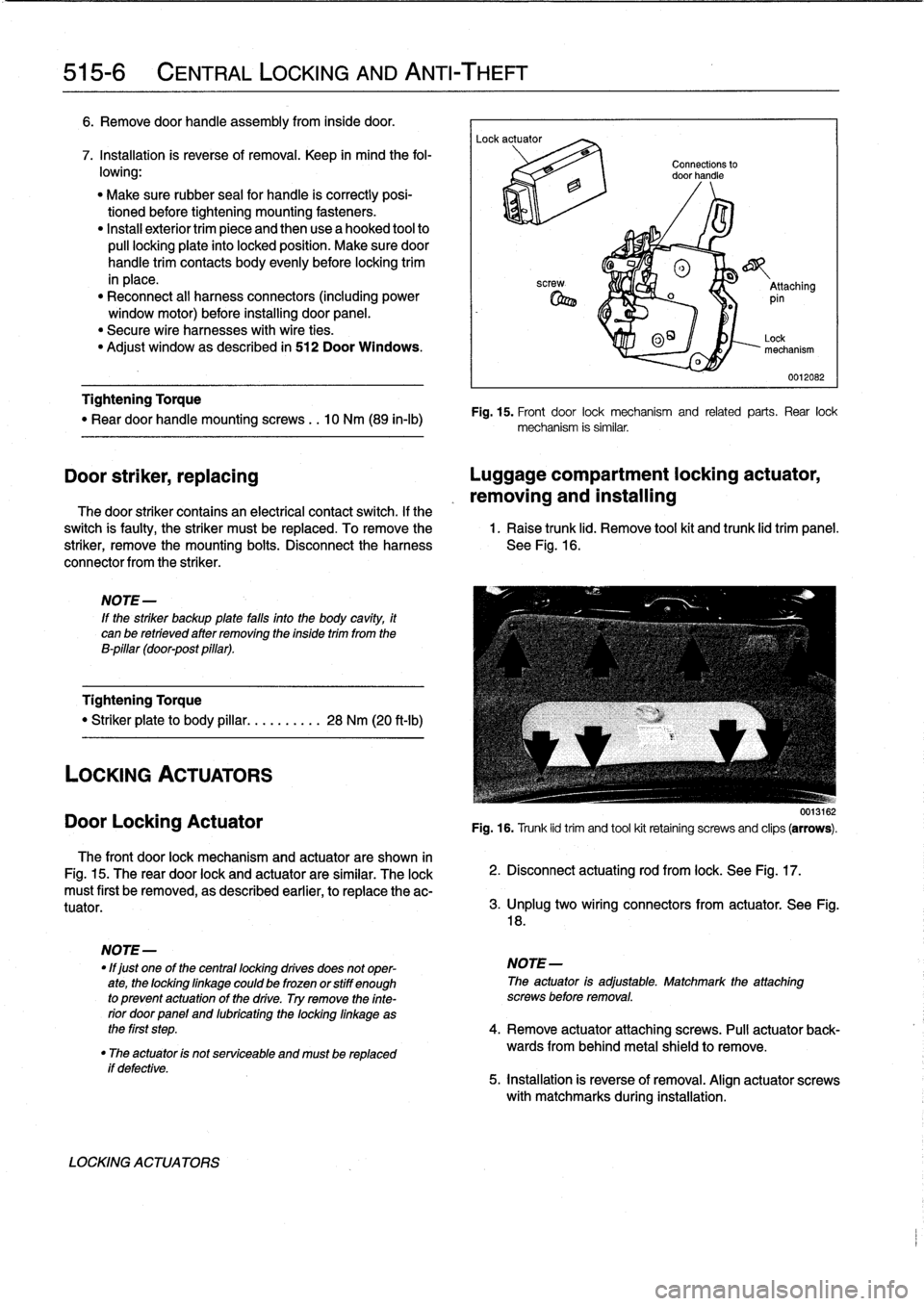
The
front
door
lock
mechanism
and
actuator
are
shown
in
Fig
.
15
.
The
rear
door
lock
and
actuator
are
similar
.
The
lock
must
first
be
removed,
as
described
earlier,
to
replace
the
ac-
tuator
.
if
defective
.
LOCKING
ACTUATORS
Connections
to
door
handle
®
o
_
Attaching
pin
0
O~
Lock
mechanism
0012082
Fig
.
15
.
Front
door
lock
mechanism
and
related
parts
.
Rear
lock
mechanism
is
similar
.
Door
striker,
replacing
Luggage
compartment
locking
actuator,
removing
and
installing
The
door
striker
contains
an
electrical
contact
switch
.
If
the
switch
is
faulty,
the
striker
must
be
replaced
.
To
remove
the
1
.
Raise
trunk
lid
.
Remove
tool
kit
and
trunk
lid
trim
panel
.
striker,
remove
the
mounting
bolts
.
Disconnect
the
harness
See
Fig
.
16
.
connector
from
the
striker
.
0013162
Fig
.
16
.
Trunk
lid
trim
and
tool
kit
retainíng
screws
and
clips
(arrows)
.
2
.
Disconnect
actuating
rod
from
lock
.
See
Fig
.
17
.
3
.
lJnplug
two
wíring
connectors
from
actuator
.
See
Fig
.
18
.
NOTE
-
"
lf
just
one
of
the
centrallocking
drives
does
not
oper-
NOTE-
ate,
the
lockinglinkage
could
be
frozen
orstiff
enough
The
actuator
is
adjustable
.
Matchmark
the
attaching
to
prevent
actuatonof
the
drive
.
Try
remove
the
finte-
screws
before
removal
.
rior
doorpanel
and
lubricating
the
locking
linkage
as
the
first
step
.
4
.
Remove
actuator
attaching
screws
.
Pull
actuator
back-
"
The
actuator
is
not
serviceable
and
mustbe
replaced
wards
from
behind
metal
shield
to
remove
.
5
.
installation
is
reverse
of
removal
.
Align
actuator
screws
with
matchmarks
during
installation
.
Page 355 of 759
002262
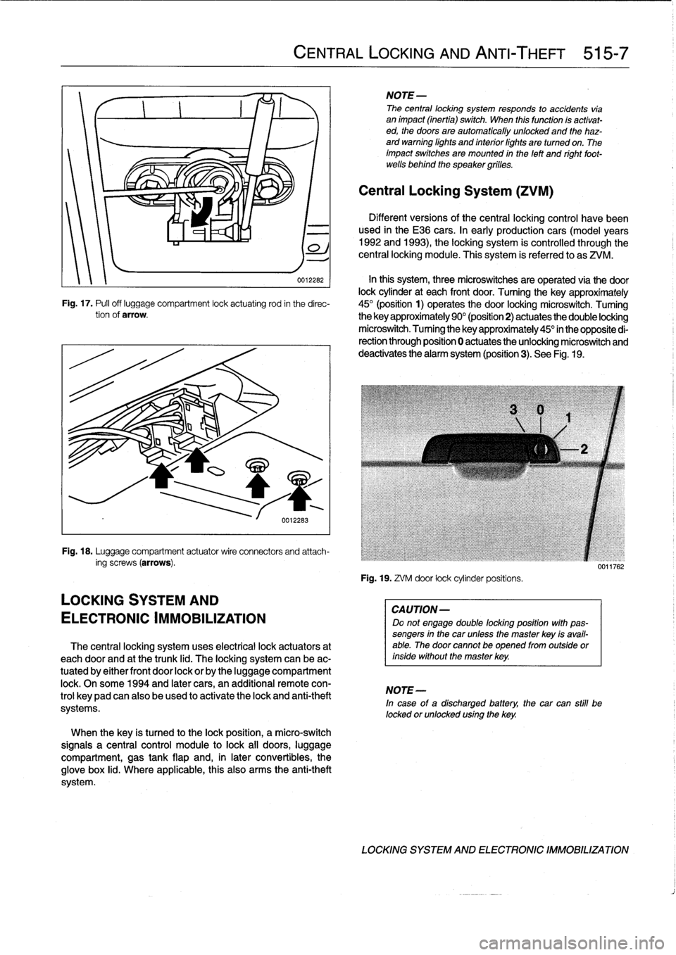
In
this
system,
three
microswitches
are
operated
via
the
door
lock
cylinder
at
each
front
door
.
Turning
the
key
approximately
Fig
.
17
.
Pufl
off
luggage
compartment
lock
actuating
rod
in
the
direc-
45°
(position
1)
operates
the
door
locking
microswitch
.
Tuming
tionof
arrow
.
the
key
approximately
90°
(position2)
actuates
the
double
locking
microswitch
.
Tuming
the
key
approximately
45°
in
the
opposite
di-
rection
through
position
0
actuates
the
unlocking
microswitch
and
deactivates
the
alarm
system
(position3)
.
See
Fig
.
19
.
Fig
.
18
.
Luggage
compartment
actuatorwire
connectors
and
attach-
ing
screws
(arrows)
.
LOCKING
SYSTEM
AND
ELECTRONIC
IMMOBILIZATION
The
central
locking
system
uses
electrical
lock
actuators
at
each
door
and
at
the
trunk
lid
.
The
locking
system
can
be
ac-
tuated
by
either
front
door
lock
or
by
the
luggage
compartment
lock
.
Onsome
1994
and
later
cars,
an
additional
remote
con-
trol
keypadcan
also
be
used
to
activate
the
lock
and
anti-theft
systems
.
When
the
key
is
tuned
to
the
lock
position,
a
micro-switch
signals
a
central
control
module
to
lock
all
doors,
luggage
compartment,
gas
tank
flap
and,
in
later
convertibles,
the
glove
box
lid
.
Where
applicable,
this
also
arms
the
anti-theft
system
.
CENTRAL
LOCKING
AND
ANTI-THEFT
515-7
NOTE-
The
central
locking
system
responds
to
accidents
vía
animpact
(inertia)
switch
.
When
this
function
ís
activat-
ed,
the
doors
are
automatically
unlocked
and
the
haz-
ard
warning
lights
and
interiorlights
are
turned
on
.
The
impact
switches
are
mounted
in
the
left
and
right
foot-
wells
behind
the
speaker
grilles
.
Central
Locking
System
(ZVM)
Different
versions
of
the
central
locking
control
havebeen
used
in
the
E36
cars
.
In
early
production
cars
(model
years
1992
and
1993),
the
locking
system
is
controlled
through
the
central
locking
module
.
This
system
is
referred
to
as
ZVM
.
Fig
.
19
.
ZVM
door
lock
cylinderpositíons
.
CAUTION-
Do
not
engage
double
locking
position
with
pas-
sengers
in
the
car
unless
the
master
key
isavail-
able
.
The
door
cannotbe
opened
from
outside
orinside
without
the
master
key
.
NOTE-
In
case
of
a
discharged
battery,
the
car
can
still
be
locked
orunlocked
using
the
key
.
0011762
LOCKING
SYSTEM
AND
ELECTRONIC
IMMOBILIZATION
Page 373 of 759
KL
30
CONVERTIBLE
BATTERY
(ON
TOP
MOTOR)
UP
DOWN
S2
-I
(ON
TOP
MOTOR)
(IN
TOP
STORAGE
WELL)
S4
E36
AUTOMATIC
CONVERTIBLE
S5
(ON
TRUNK
LOCK)I
TOP
CONTROLMODULE
I
LH
SIDE
TOP
LATCH
DRIVE)
1
M-4
m
í
A
7--
Offi-
Íl
ít~~
ENSOR
H
ARD
T
OP
LOCK
SIGNAL
O
1~~11
:i
q
SIGNAL
TOP
MOTOR
POSITION
SIGNAL
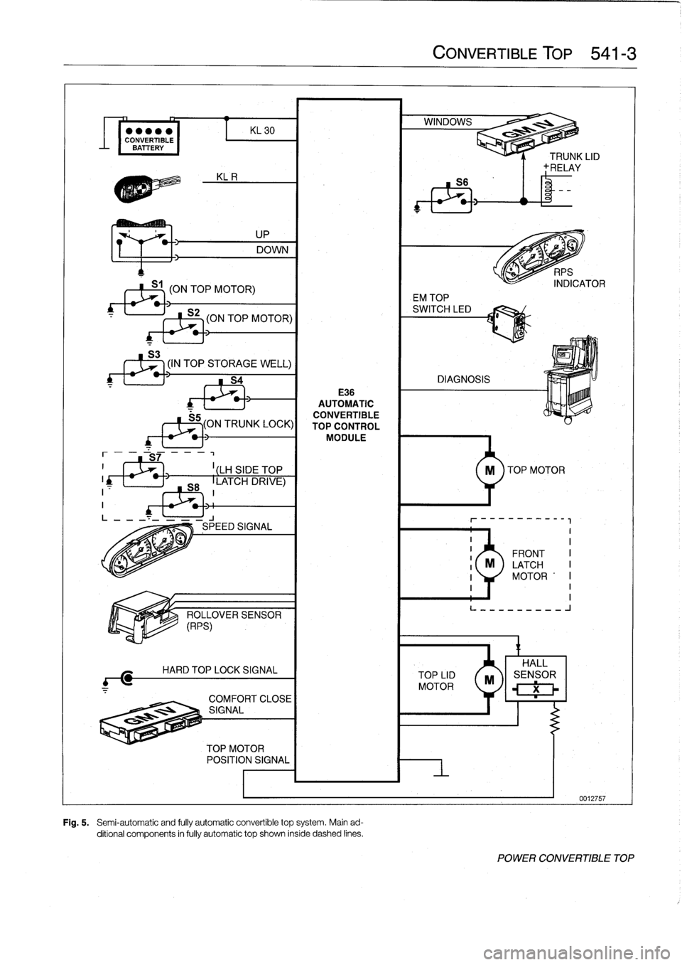
Fig
.
5
.
Semi-automatic
and
fully
automatic
convertible
top
system
.
Main
ad-
ditional
components
in
fully
automatic
top
shown
inside
dashed
lines
.
CONVERTIBLE
TOP
541-3
TOP
LID
MOTOR
EM
TOP
n
~
ll
í
9
.1
-----------
II
II
FRONT
I
M
LATCH
I
1
MOTOR
'I
I
1I
L---------
J
X
POWER
CONVERTIBLE
TOP
Page 397 of 759
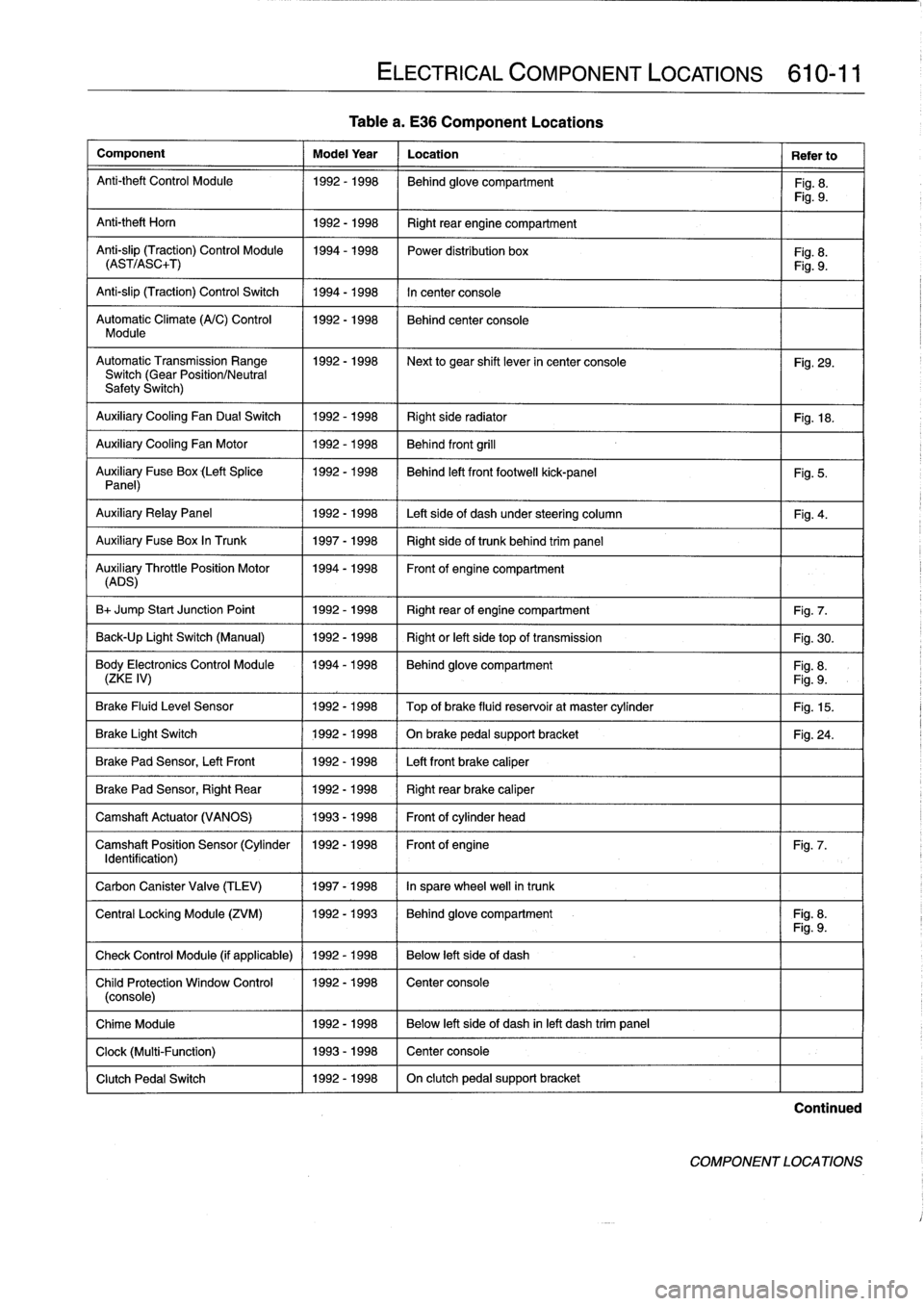
Table
a
.
E36
Component
Locations
Component
Model
Year
Location
Refer
to
Anti-theft
Control
Module
1992-1998
Behind
glove
compartment
Fig
.
8
.
Fig
.
9
.
Anti-theft
Horn
1
1992-1998
1
Right
rear
engine
compartment
Anti-slip
(Traction)
Control
Module
1994-1998
Power
distribution
box
Fig
.
8
.
(AST/ASC+T)
Fig
.
9
.
Anti-slip
(Traction)
Control
Switch
1994-1998
In
center
console
Automatic
Climate
(A/C)
Control
1992-1998
Behind
center
console
Module
AutomaticTransmission
Range
1992-1998
~
Next
to
gear
shift
lever
in
center
console
Fig
.
29
.
Switch
(Gear
Position/Neutral
Safety
Switch)
Auxiliary
Cooling
Fan
Dual
Switch
1992-1998
Right
side
radiator
1
Fig
.
18
.
Auxiliary
Cooling
Fan
Motor
1992-1998
Behind
front
grill
Auxiliary
Fuse
Box
(Left
Splice
1992-1998
I
Behind
left
front
footwell
kick-panel
Panel)
Auxiliary
RelayPanel
1
1992-1998
1
Left
side
of
dash
under
steering
column
Auxiliary
Fuse
Box
In
Trunk
1
1997-1998
1
Right
sideof
trunk
behind
trim
panel
AuADSry
ThrottlePosition
Motor
11994-1998
Front
of
engine
compartment
B+
Jump
Start
Junction
Point
1992-1998
Right
rear
of
engine
compartment
Fig
.
7
.
Back-Up
Light
Switch
(Manual)
1992-1998
Right
or
left
side
top
of
transmission
Fig
.
30
.
Body
Electronics
Control
Module
1994-1998
Behindglove
compartment
Fig
.
8
.
(ZKE
IV)
Fig
.
9
.
Brake
Fluid
Level
Sensor
1992-1998
Top
of
brake
fluid
reservoir
at
master
cylinder
Fig
.
15
.
Brake
Light
Switch
1
1992-1998
1
On
brake
pedal
supportbracket
Brake
Pad
Sensor,
Left
Front
1
1992-1998
1
Left
front
brake
caliper
Brake
Pad
Sensor,
Right
Rear
1992-1998
Right
rear
brake
caliper
Camshaft
Actuator
(VANOS)
1993-1998
Front
of
cylinder
head
Camshaft
Position
Sensor
(Cylinder
1992-1998
Front
of
engine
Identification)
Carbon
Canister
Valve
(TLEV)
1
1997-1998
1
In
sparewheel
well
in
trunk
ELECTRICAL
COMPONENT
LOCATIONS
610-11
Fig
.
5
.
Fig
.
4
.
Fig
.
24
.
Fig
.
7
.
Central
Locking
Module
(ZVM)
11992-1993
1
Behindglove
compartment
I
Fig
.
8
.
Fig
.
9
.
Check
Control
Module
(if
applicable)
1
1992
-
1998
1
Below
left
side
of
dash
Child
Protection
Window
Control
1992-1998
Center
console
(console)
Chime
Module
1992-1998
Below
left
side
of
dash
inleft
dash
trim
panel
Clock
(Multi-Function)
1993-1998
Center
console
Clutch
Pedal
Switch
1992-1998
On
clutch
pedal
support
bracket
Continued
COMPONENT
LOCATIONS
Page 398 of 759
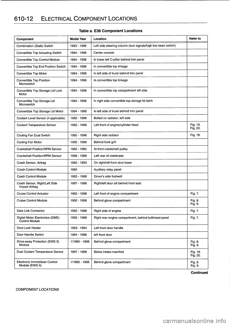
610-12
ELECTRICAL
COMPONENT
LOCATIONS
Table
a
.
E36
Component
Locations
Component
Model
Year
Location
Refer
to
Combination
(Stalk)
Switch
1993-1998
Left
sidesteering
column
(turn
signals/high-low
bean
switch)
Convertible
Top
ActuatingSwitch
1994-1998
Center
console
Convertible
Top
Control
Module
1994-1998
In
lower
left
C-pillar
behind
trim
panel
Convertible
TopEnd
Position
Switch
1994-1998
In
convertible
top
linkage
Convertible
Top
Motor
1994-1998
In
left
sideof
trunk
behind
trim
panel
Convertible
Top
Position
1994-1998
In
convertible
top
linkage
Microswitch
Convertible
Top
Storage
Lid
Lock
1994-1998
In
convertible
top
compartment
left
side
Motor
Convertible
Top
Storage
Lid
1994-1998
Inright
side
convertible
top
storage
lid
latch
Microswitch
Convertible
Top
Storage
Lid
Motor
1994-1998
In
left
side
of
trunk
behind
trim
panel
Coolant
Leve¡
Sensor
(if
applicable)
1992-1998
Bolted
on
radiator,
left
side
Coolant
Temperature
Sensor
1992-1998
Left
front
of
engine/cylinder
head
Fig
.
19
.
Fig
.
20
.
Cooling
Fan
Dual
Switch
1992-1998
Right
side
radiator
Fig
.
18
.
Cooling
Fan
Motor
1992-1998
Behind
front
grill
Crankshaft
Position/RPM
Sensor
1992-1995
At
front
crankshaft
pulley
Crankshaft
Position/RPM
Sensor
1996-1998
Left
rearof
crankcase
Crash
Sensor,
Airbag
1992-1993
On
right/left
frontstrut
tower
Crash
Control
Module
1992
Auxiliary
relay
panel
Crash
Control
Module
1993-1998
Driver's
side
footwell
Crash
Sensor,
Right/Left
Side
1997-1998
Right/left
door
sill
behind
front
seat
Impact
Airbag
Cruise
Control
Actuator
1992-1998
Left
front
of
engine
compartment
Fig
.
7
.
Cruise
Control
Module
1992-1998
Behind
glove
compartment
Fig
.
8
.
Fig
.
9
.
Data
Link
Connector
1992-1998
Right
sideof
engine
Fig
.
7
.
Digital
Motor
Electronics
(DME)
1992-1998
Right
rear
engine
compartment,
behind
bulkhead
panel
Fig
.
7
.
Control
Module
DoorLock
Heater
1993-1994
Left
front
doorhandle
DoorHandle
Switch
1994-1998
left
front
door
Drive-away
Protection
(EWS
II)
1/1995
-
1998
Behind
glove
compartment
Fig
.
8
.
Module
Fig
.
9
.
Dual
Coolant
Temperature
Sensor
1997-1998
Below
intake
manifold
Fig
.
19
.
COMPONENT
LOCATIONS
Fig
.
20
.
Electronic
Immobilizer
Control
(
1/1995-1998
~
Behind
glove
compartment
Fig
.
8
.
Module
(EWS
II)
Fig
.
9
.
Continued
Page 400 of 759
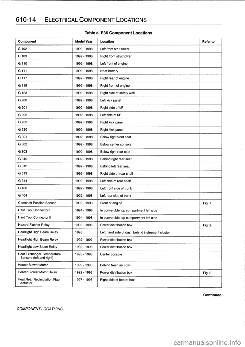
610-14
ELECTRICAL
COMPONENT
LOCATIONS
Component
Model
Year
Location
Refer
to
G
102
1992-1998
Left
front
strut
tower
G
103
1992-1998
Right
front
strut
tower
G
110
1992-1998
Left
front
of
engine
G
111
1992-1998
Near
battery
G
117
1992-1998
Right
rearof
engine
G
119
1992-
1998
Right
front
of
engine
G
123
1992-1998
Right
side
of
safety
wall
G
200
1992-1998
Left
kick
panel
G
201
1992-1998
Right
side
ofI/P
G
202
1992-1998
Left
side
ofI/P
G
203
1992-1998
Right
kick
panel
G
230
1992-1998
Right
kick
panel
G
301
1992-1998
Below
rightfront
seat
G
302
1992-1998
Below
center
console
G
303
1992-1998
Below
right
rear
seat
G
310
1992-1998
Behind
right
rear
seat
G
312
1992-1998
Behind
left
rear
seat
G
313
1992-1998
Right
side
of
rear
shelf
G
314
1992-1998
Left
side
of
rear
shelf
G
400
1992-1998
Left
front
side
of
trunk
G
404
1992-1998
Left
rearside
of
trunk
Camshaft
Position
Sensor
1992-1998
Front
of
engine
Fig
.
7
.
Hard
Top,
Connector
1
1994-1998
In
convertible
top
compartment
left
side
Hard
Top,
Connector
II
1994-1998
In
convertible
top
compartment
left
side
Hazard
Flasher
Relay
1992-1998
Power
distribution
box
Fig
.
2
.
Headlight
High
Beam
Relay
1998
Left
hand
side
of
dash
behind
instrument
cluster
Headlight
High
Beam
Relay
1992-1997
Power
distribution
box
Headlight
Low
Beam
Relay
1992-1998
Power
distribution
box
Heat
ExchangerTemperature
1993-1998
Center
console
Sensors
(left
and
right)
HeaterBlower
Motor
1992-1998
Behind
fresh
air
cowl
HeaterBlower
Motor
Relay
1992-1998
Power
distribution
box
Fig
.
2
.
Heat
Rear
Recirculation
Flap
1997-1998
Right
sideof
heater
box
Actuator
COMPONENTLOCATIONS
Tablea
.
E36
Component
Locations
Continued