door lock BMW 318i 1995 E36 Owner's Manual
[x] Cancel search | Manufacturer: BMW, Model Year: 1995, Model line: 318i, Model: BMW 318i 1995 E36Pages: 759
Page 356 of 759
515-8
CENTRAL
LOCKING
AND
ANTI-THEFT
Central
Body
Electronics
(ZKE
IV)
Electronic
Immobilization
System
(EWS)
Beginning
withvehicles
produced
9193
(model
year
1994),
The
electronic
anti-theft
system
known
as
EWS
was
first
in-
the
centrallocking
system
was
integrated
with
sunroof
and
troduced
in
January
1994
.
The
early
version
of
the
system
window
closure
into
the
Central
Body
Electronics
(ZKE
IV)
uses
a
starting
inhibition
module
to
interrupt
the
ignition,
the
(generation
four)
system
.
The
control
module
for
this
system
fuel
injection
and
the
starter
motor
.
This
system
is
activated
ís
mounted
in
front
of
the
glove
compartment
.
and
deactivated
by
the
centrallockíng
system
.
The
control
module
for
the
system
is
installed
under
the
left
side
of
the
Inthis
system
two
microswítches
are
operated
viathe
door
dashboard
.
lock
cylinder
at
both
front
doors
.
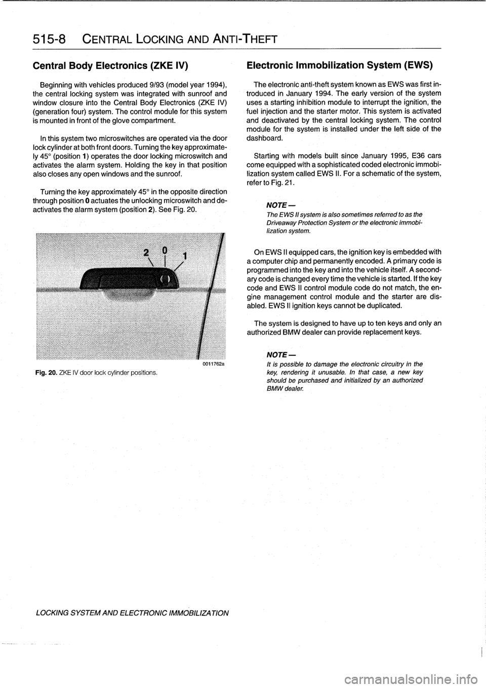
Turning
the
key
approximate-
ly
45°
(position
1)
operates
the
door
locking
microswitch
and
Startingwith
modeis
built
since
January
1995,
E36
cars
activates
the
alarm
system
.
Holding
the
key
in
thatposition
come
equipped
with
a
sophisticated
coded
electronic
immobi
also
closes
any
open
windows
and
the
sunroof
.
lization
system
called
EWS
II
.
Foraschematic
of
the
system,
refer
to
Fig
.
21
.
Turning
the
key
approximately
45°
in
the
opposite
direction
through
position
0
actuates
theunlocking
microswitch
and
de-
activates
the
alarm
system
(position
2)
.
See
Fig
.
20
.
NOTE
-
The
EWS
11
system
is
also
sometimes
referred
to
as
the
Driveaway
Protection
System
or
the
electronic
immobi-
lization
system
.
On
EWS
II
equipped
cars,
the
ignition
key
is
embedded
with
a
computer
chip
and
permanently
encoded
.
A
primary
code
is
programmed
into
the
keyand
finto
the
vehicle
itself
.
A
second-
ary
code
is
changed
every
time
the
vehicle
is
started
.
If
thekey
code
and
EWS
II
control
module
code
do
notmatch,
the
en-
gine
management
control
module
and
the
starter
are
dis-
abled
.
EWS
II
ignition
keyscannot
be
duplicated
.
The
system
is
designed
to
have
up
to
ten
keys
and
only
an
authorized
BMW
dealer
can
provide
replacement
keys
.
j
NOTE-
0011762a
ft
is
possible
to
damage
the
electronic
circuítry
in
the
Fig
.
20
.
ZKE
IV
door
lock
cylinder
positions
.
key,
rendering
if
unusable
.
In
that
case,
a
new
key
shouldbe
purchased
and
initialized
byan
authorized
BMW
dealer
.
LOCKING
SYSTEM
AND
ELECTRONIC
IMM081LIZATION
Page 361 of 759
GENERAL
This
repair
group
covers
removal
and
installation
of
the
front
and
rear
seats
.
FRONT
SEATS
The
front
seats
installed
in
E36
cars
come
in
either
manual
or
electrically
powered
versions
.
Cloth,vinyl
and
leather
ver-
sions
are
offered
.
M3
sport
seats
have
extra
bolsters
on
the
sides
of
the
sean-back,
a
thigh
support
bolster,
and
extra
con-
trols
for
sean
inclination
.
Seat
removal
and
installation
is
similar
for
all
versions
.
Seat
disassembly
differs
in
details
among
the
many
models
of
seats
.
Front
seat,
removing
and
installing
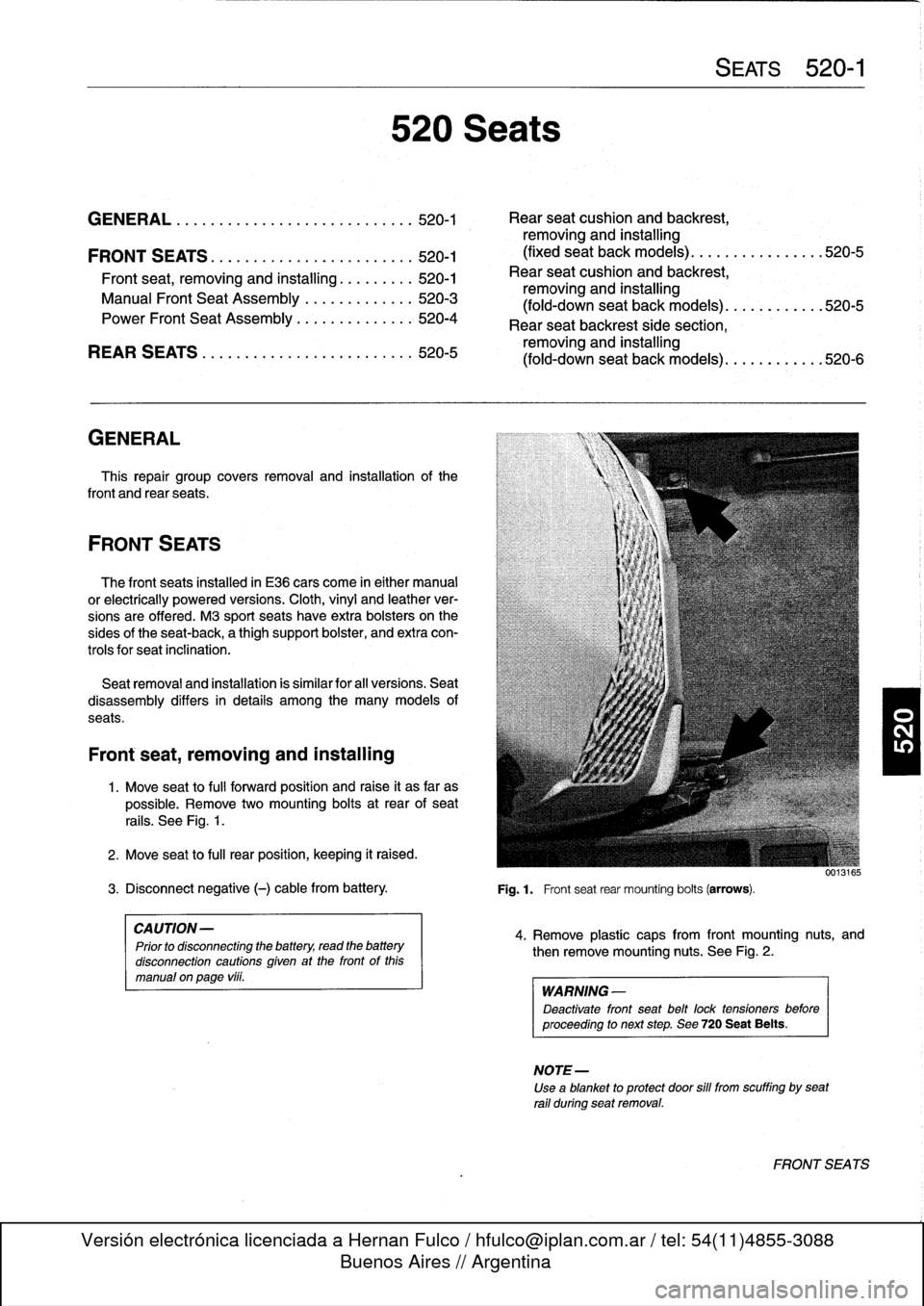
1
.
Move
seat
to
fui¡
forward
position
and
raise
it
as
far
as
possible
.
Remove
two
mounting
bolts
at
rear
of
sean
rails
.
See
Fig
.
1
.
2
.
Move
seat
to
fui¡
rear
position,
keeping
it
raised
.
3
.
Disconnect
negative
(-)
cable
from
battery
.
Fig
.1
.
Frontseat
rear
mounting
bolts
(arrows)
.
CAUTION-
Prior
to
disconnecting
the
battery,
read
the
battery
disconnection
cautions
given
at
the
front
of
this
manual
onpage
viii
.
520
Seats
SEATS
520-1
GENERAL
...
.
.
.
.
.
.
.
.
.
..............
.
.
520-1
Rear
seat
cushion
and
backrest,
removing
and
installing
FRONT
SEATS
.
.
.
.
.
.
......
.
.
.
...
.
.
.
.
.
.
520-1
(fixed
seat
back
models)
......
.
.
.
...
.
...
520-5
Front
seat,
removing
and
installing
...
.
.
.
..'
520-1
Rear
seat
cushion
and
backrest,
Manual
Front
Seat
Assembly
.............
520-3
removing
and
installing
fold-downsean
back
models
(
)
..
.
.
..
..
.
...
520-5
Power
Fronf
Seat
Assembly
..
.
.....
.
.
.
.
.
;
520-4
Rear
seat
backrest
side
section,
REAR
SEATS
.
.
.
.
.
.
.
.
.
............
.
...
520-5
removing
and
installing
(fold-down
seat
back
models)
..
.
.....
.
..
.520-6
4
.
Remove
plastic
caps
from
front
mounting
nuts,
and
then
remove
mounting
nuts
.
See
Fig
.
2
.
WARNING
-
Deactivate
front
seat
belt
lock
tensioners
before
proceeding
to
next
step
.
See720
Seat
Belts
.
NOTE-
Use
a
blanket
to
protect
door
sill
from
scuffing
bysean
rail
during
seatremoval
.
FRONT
SEA
TS
Page 362 of 759
520-2
S
EATS
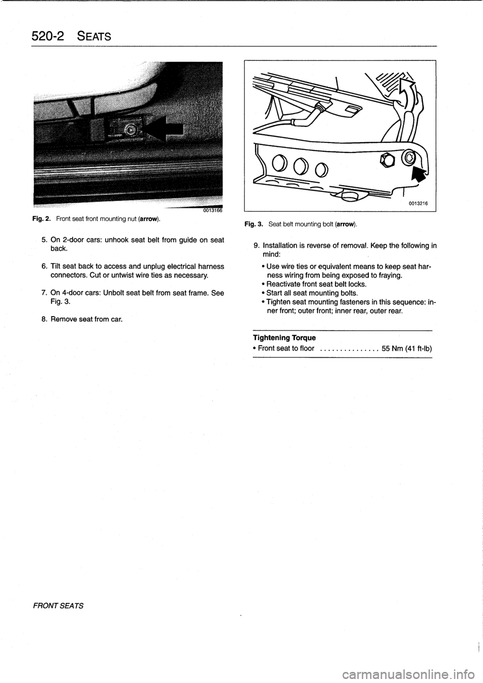
Fig
.
2
.
Frontseat
front
mounting
nut
(arrow)
.
FRONT
SEA
TS
0013166
5
.
On
2-door
cars
:
unhook
seat
belt
from
guide
on
seat
back
.
8
.
Remove
seatfrom
car
.
Fig
.
3
.
Seat
belt
mounting
bolt
(arrow)
.
0013216
9
.
Installation
is
reverse
of
removal
.
Keep
the
following
in
mind
:
6
.
Tilt
seat
back
to
access
and
unplug
electrical
harness
"
Use
wire
ties
orequivalent
means
to
keep
seat
har
connectors
.
Cut
or
untwist
wire
ties
as
necessary
.
ness
wiring
from
being
exposed
to
fraying
.
"
Reactivate
front
seat
belt
locks
.
7
.
On
4-door
cars
:
Unbolt
seat
belt
from
seat
frame
.
See
"
Start
all
seat
mounting
boits
.
Fig
.
3
.
"
Tighten
seat
mounting
fasteners
in
thís
sequence
:
in-
ner
front
;
outer
front
;
inner
rear,
outer
rear
.
Tightening
Torque
"
Front
seat
to
floor
........
.......
55
Nm
(41
ft-Ib)
Page 372 of 759
541-2
CONVERTIBLE
TOP
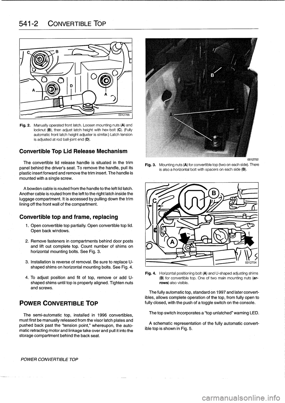
Fig
.
2
.
Manually
operated
frontlatch
.
Loosen
mounting
nuts
(A)
and
locknut
(B),
then
adjust
latch
height
with
hex-bolt
(C)
.
(Fully
automatic
front
latch
height
adjuster
is
similar
.)
Latch
tension
ís
adjusted
at
rod
ball-joint
end
(D)
.
Convertible
Top
Lid
Release
Mechanism
The
convertible
lid
release
handle
is
situated
in
the
trim
panel
behind
the
driver's
seat
.
To
remove
thehandle,
pull
its
plastic
insert
forward
and
remove
the
triminsert
.
The
handle
is
mounted
with
a
single
screw
.
Abowden
cable
is
routed
from
the
handle
to
the
left
lid
latch
.
Another
cable
is
routed
from
the
left
tothe
right
latch
inside
the
luggage
compartment
.
It
is
accessed
by
pulling
down
the
trim
lining
off
the
front
wall
of
the
compartment
.
Convertible
top
and
frame,
replacing
1
.
Open
convertible
top
partially
.
Open
convertible
top
lid
.
J
I~I~KX
Open
back
windows
.
_
v
2
.
Remove
fasteners
in
compartments
behind
door
posts
and
lift
out
complete
top
.
Count
number
of
shims
on
horizontal
mounting
bolts
.
See
Fig
.
3
.
3
.
Installation
is
reverse
of
removal
.
Be
sure
to
replaceU-
shaped
shims
on
horizontal
mounting
bolts
.
See
Fig
.
4
.
Fig
.
4
.
Horizontal
positioning
bolt(A)
and
U-shaped
adjusting
shims4
.
To
adjust
position
and
fit
oftop,
remove
or
add
U-
(B)for
convertible
top
.
One
of
two
main
mounting
nuts
(ar
shaped
shims
until
top
is
properly
aligned
.
Tighten
nuts
rows)
also
visible
.
and
screws
.
POWER
CONVERTIBLE
TOP
The
semi-automatic
top,
installed
in
1996
convertibles,
must
first
be
manually
released
from
the
visor
latch
plates
and
pushed
back
past
the
"tension
point,"
wheréupon,
the
auto-
matic
retracting
motor
and
linkage
take
over
and
pull
it
into
the
storage
compartment
behind
the
back
seat
.
POWER
CONVERTIBLE
TOP
Fig
.
3
.
Mounting
nuts
(A)
for
convertible
top
(two
oneach
side)
.
There
is
also
a
horizontal
bolt
with
spacers
oneach
side
(B)
.
0012754
The
fully
automatic
top,
standard
on
1997
and
later
convert-
ibles,
allows
complete
operation
of
the
top,
from
fully
open
to
fully
closed,withthe
push
of
atoggleswitch
on
the
console
.
The
top
switch
incorporates
a
"top
unlatched"
warning
LED
.
A
schematic
representation
of
the
fully
automatic
convert-
ible
top
is
shown
in
Fig
.
5
.
Page 390 of 759
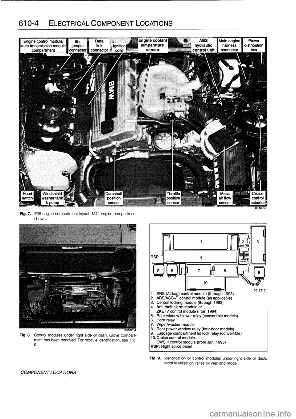
610-4
ELECTRICAL
COMPONENT
LOCATIONS
--J
L
Windshield
washertank
&
pump
Fig
.
7
.
E36
engine
compartment
layout
.
M42
engine
compartment
shown
.
-,x
0013204
Fig
.
8
.
Control
modules
under
right
sideof
dash
.
Glove
compart-
ment
has
been
removed
.
For
module
identification,
see
Fig
.
9
.
COMPONENT
LOCATIONS
RSP
'I
4
ABS
Main
engine
Power
hydraulic
harness
distribution
control
unit
connector
I
box
oe
1
.
SRS
(Airbag)
control
module
(through
1993)
2
.
ABS/ASC+T
control
module
(as
applicable)
3
.
Central
locking
module
(through
1993)
4
.
Anti-theft
alarm
module
or
ZKE
IV
control
module
(from
1994)5
.
Rear
window
blower
relay
(convertible
models)6
.
Horn
relay
7
.
Wiper/washer
module
8
.
Rear
power
window
relay
(four-door
models)9
.
Luggage
compartment
lid
lock
relay
(convertible)
10
.
Cruise
control
module
EWS
II
control
module
(from
Jan
.
1995)
RSP
:
Right
splice
panel
0013215
Fig
.
9
.
Identificationof
control
modules
under
right
side
of
dash
.
Module
utilízation
varies
byyear
andmodel
Page 398 of 759
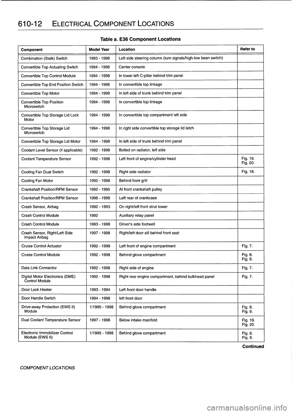
610-12
ELECTRICAL
COMPONENT
LOCATIONS
Table
a
.
E36
Component
Locations
Component
Model
Year
Location
Refer
to
Combination
(Stalk)
Switch
1993-1998
Left
sidesteering
column
(turn
signals/high-low
bean
switch)
Convertible
Top
ActuatingSwitch
1994-1998
Center
console
Convertible
Top
Control
Module
1994-1998
In
lower
left
C-pillar
behind
trim
panel
Convertible
TopEnd
Position
Switch
1994-1998
In
convertible
top
linkage
Convertible
Top
Motor
1994-1998
In
left
sideof
trunk
behind
trim
panel
Convertible
Top
Position
1994-1998
In
convertible
top
linkage
Microswitch
Convertible
Top
Storage
Lid
Lock
1994-1998
In
convertible
top
compartment
left
side
Motor
Convertible
Top
Storage
Lid
1994-1998
Inright
side
convertible
top
storage
lid
latch
Microswitch
Convertible
Top
Storage
Lid
Motor
1994-1998
In
left
side
of
trunk
behind
trim
panel
Coolant
Leve¡
Sensor
(if
applicable)
1992-1998
Bolted
on
radiator,
left
side
Coolant
Temperature
Sensor
1992-1998
Left
front
of
engine/cylinder
head
Fig
.
19
.
Fig
.
20
.
Cooling
Fan
Dual
Switch
1992-1998
Right
side
radiator
Fig
.
18
.
Cooling
Fan
Motor
1992-1998
Behind
front
grill
Crankshaft
Position/RPM
Sensor
1992-1995
At
front
crankshaft
pulley
Crankshaft
Position/RPM
Sensor
1996-1998
Left
rearof
crankcase
Crash
Sensor,
Airbag
1992-1993
On
right/left
frontstrut
tower
Crash
Control
Module
1992
Auxiliary
relay
panel
Crash
Control
Module
1993-1998
Driver's
side
footwell
Crash
Sensor,
Right/Left
Side
1997-1998
Right/left
door
sill
behind
front
seat
Impact
Airbag
Cruise
Control
Actuator
1992-1998
Left
front
of
engine
compartment
Fig
.
7
.
Cruise
Control
Module
1992-1998
Behind
glove
compartment
Fig
.
8
.
Fig
.
9
.
Data
Link
Connector
1992-1998
Right
sideof
engine
Fig
.
7
.
Digital
Motor
Electronics
(DME)
1992-1998
Right
rear
engine
compartment,
behind
bulkhead
panel
Fig
.
7
.
Control
Module
DoorLock
Heater
1993-1994
Left
front
doorhandle
DoorHandle
Switch
1994-1998
left
front
door
Drive-away
Protection
(EWS
II)
1/1995
-
1998
Behind
glove
compartment
Fig
.
8
.
Module
Fig
.
9
.
Dual
Coolant
Temperature
Sensor
1997-1998
Below
intake
manifold
Fig
.
19
.
COMPONENT
LOCATIONS
Fig
.
20
.
Electronic
Immobilizer
Control
(
1/1995-1998
~
Behind
glove
compartment
Fig
.
8
.
Module
(EWS
II)
Fig
.
9
.
Continued
Page 401 of 759
Component
Model
Year
Location
Refer
to
Heater
Recirculation
Flap
Actuator
1992-1998
Below
left
dash
right
side
of
steering
column
HeaterBlowerMotor
Resistor
Pack
1992-1998
Behind
center
of
dashboard
Heater
Regulator
FlapActuator
1997-1998
Right
side
of
heater
box
HeaterValve
Assembly
1992-1998
Left
rear
engine
compartment
HeatingNentilation
Relay
Box
1992-1993
Below
left
side
of
dash
HeatingNentilation
Relay
1994-1998
Left
front
footwell
High
Speed
Cooling
Fan
Relay
1992-1998
Power
distribution
box
Fig
.
2
.
Homs,
Right/Left
1993-1998
Front
of
engine
compartment
Horn
Relay
1992-1998
Power
distribution
box
Fig
.
2
.
Horn
Relay
(Alpine)
1994-1998
Behind
glove
compartment
Fig
.
8
.
Board
Computer/Anti-Theft
Fig
.
9
.
Idle
Speed
Control
Valve
1992-1995
Top
rearof
enginebehind
intake
manifold
(M42
engine)
Fig
.
11
.
Idle
Speed
Control
Valve
1992-1995
Top
left
side
of
engine
(M50
engine)
Idle
Speed
Control
Valve
1993-1996
Below
intake
manifold
(M50/S50US
engine)
Idle
Speed
Control
Valve
1996-1998
On
throttle
housing
(M44
engine)
Fig
.
15
.
Idle
Speed
Control
Valve
1997-1998
Left
front
of
engine
below
intake
manifold
(M52/S52US
engine)
Ignition
Coils
1992-1998
Right
of
engineunder
plastic
cover
(four-cylinder)
Fig
.
7
.
Ignition
Cofs
1992-1998
Top
of
engine
undercover
(six-cylinder)
Fig
.
17
.
Ignition
Switch
1992-1998
Right
sídeofsteering
column
Intake
Air
Resonance
Changeover
1992-1998
Leftrear
of
engine
compartment
Valve(DISA)
Intake
Air
Temperature
Sensor
1992-1995
In
mass
air
flow
sensor
(M42
engine)
Intake
Air
TemperatureSensor
1996-1998
In
top
ofair
filter
housing
(M44
engine)
Fig
.
12
.
Intake
Air
Temperature
Sensor
1992-1998
I
Left
sídeof
engine
in
intake
manifold
(six-cylinder)
-
-
I
Fig
.
13
.
Fig
.
14
.
Kick-Down
Switch
(A/T)
1
1992-1998
1
Left
footwell
Mixing
Actuators
1
1992-1998
1
Heater
box
ELECTRICAL
COMPONENT
LOCATIONS
610-15
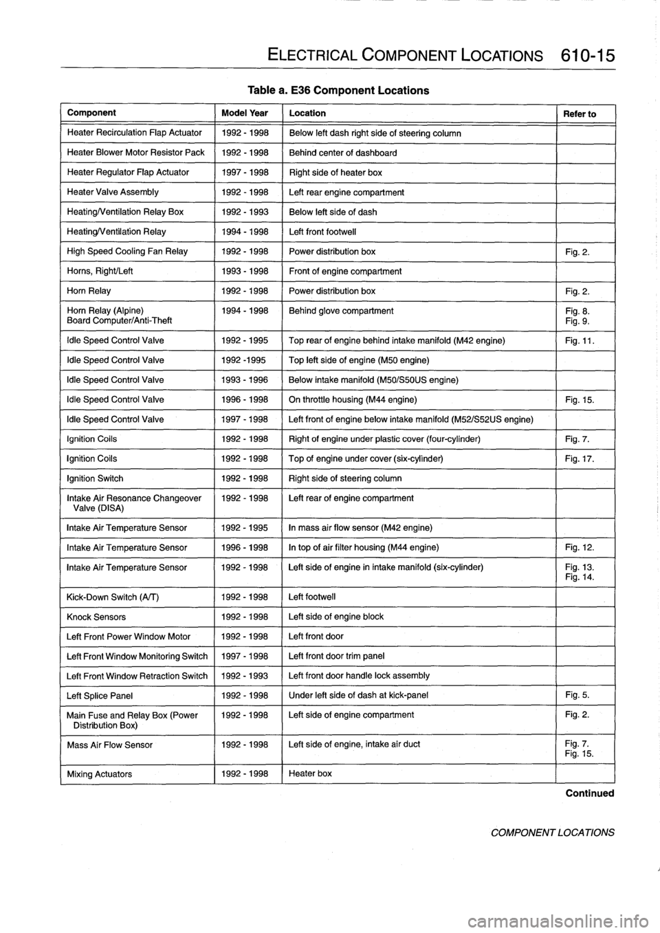
Table
a
.
E36
Component
Locations
Knock
Sensors
1
1992-1998
1
Left
side
of
engine
block
Left
Front
Power
Window
Motor
11992-1998
/
Left
front
door
Left
Front
Window
Monitoring
Switch
1
1997-1998
1
Left
front
door
trim
panel
Left
Front
Window
Retraction
Switch
1
1992
-
1993
1
Left
front
door
handle
lock
assembly
Left
Splice
Panel
1
1992-1998
1
Under
left
side
of
dash
at
kick-panel
1
Fig
.
5
.
Main
Fuse
and
Relay
Box
(Power
1992-1998
I
Left
sideof
engine
compartment
Fig
.
2
.
Distribution
Box)
1
I
Mass
Air
Flow
Sensor
1992-1998
I
Left
side
of
engine,
intake
air
duct
Fig
.
7
.1
I
Fig
.
15
.
Continued
COMPONENT
LOCATIONS
Page 403 of 759
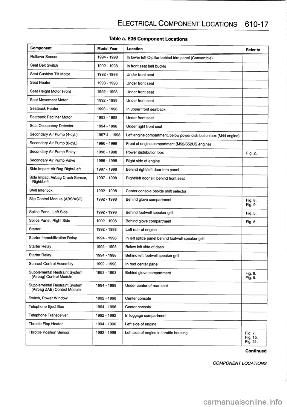
Tablea
.
E36
Component
Locations
Component
Model
Year
Location
Refer
to
Rollover
Sensor
1994-1998
In
lower
left
C-pillar
behind
trim
panel
(Convertible)
Seat
Belt
Switch
1992-1998
In
front
seat
belt
buckle
SeatCushion
Tilt
Motor
1992-1998
Under
front
seat
Seat
Heater
1993-1998
Under
front
seat
Seat
Height
Motor
Front
1992-1998
Under
front
seat
Seat
Movement
Motor
1992-1998
Under
front
seat
Seatback
Heater
1993-1998
In
upper
front
seatback
Seatback
Recliner
Motor
1993-1998
Under
front
seat
Seat
Occupancy
Detector
1994-1998
Under
rightfront
seat
Secondary
Air
Pump
(4-cyl
.)
1997
1
/2
-
1998
Left
engine
compartment,
belowpower
distribution
box
(M44
engine)
Secondary
Air
Pump
(6-cyl
.)
1996-1998
Front
of
engine
compartment
(M52/S52US
engine)
Secondary
Air
Pump
Relay
1996-1998
Power
distribution
box
Fig
.
2
.
Secondary
Air
Pump
Valve
1996-1998
Right
sideof
engine
Side
Impact
Air
Bag
Right/Left
1997-1998
Behind
right/left
door
trim
panel
Síde
Impact
Airbag
Crash
Sensor,
1997-1998
Right/left
door
si¡¡
behind
front
seat
Right/Left
Shift
Interlock
1992-1998
Center
console
beside
shift
selector
Slip
Control
Module
(ABS/AST)
1992-1998
Behind
glove
compartment
Fig
.
8
.
Fig
.
9
.
Splice
Panel,
Left
Side
1992-1998
Behind
footwell
speaker
grill
Fig
.
5
.
SplicePanel,
Right
Side
1992-1998
Behind
glove
compartment
Fig
.
6
.
Starter
1992-1998
Leftrear
of
engine
Starter
Immobilization
Relay
1994-1998
In
left
splice
panelbehind
footwell
speaker
grill
Starter
Relay
1992-1993
Below
left
side
of
dash
Starter
Relay
1994-1998
Behind
left
footwell
speaker
grill
Sunroof
Control
Assembly
1992-1998
In
roof
center
panel
Supplemental
Restraint
System
11992-1993
I
Behind
glove
compartment
I
Fig
.
8
.
(Airbag)
Control
Module
Fig
.
9
.
Supplemental
Restraint
System
1994-1998
1
Under
center
of
rear
seat
(Airbag
ZAE)
Control
Module
Switch,
Power
Window
1
1992-1998
1
Center
console
Telephone
Eject
Box
1
1994-1996
1
Center
console
ELECTRICAL
COMPONENT
LOCATIONS
610-17
Telephone
Transceiver
1992-1992
In
luggage
compartment
Throttle
Flap
Heater
1994-1996
Left
sideof
engine
Throttle
Position
Sensor
1992-1998
I
Left
sideof
engine
inthrottle
housing
I
Fig
.
7
.
Fig
.
15
.
Fig
.
21
.
Continued
COMPONENT
LOCATIONS
Page 413 of 759
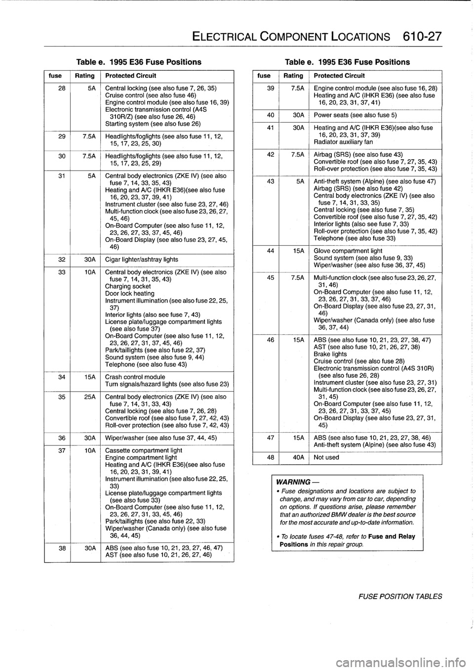
Tablee
.
1995
E36
Fuse
Positions
Table
e
.
1995
E36
Fuse
Positions
fuse
I
Rating
1
Protected
Circuit
28
5A
Central
locking
(see
alsofuse
7,
26,
35)Cruise
control
(see
also
fuse
46)Engine
control
module
(see
also
f
use
16,
39)
Electronic
transmission
control
(A4S
310R/Z)
(see
also
f
use
26,
46)
Starting
system
(seealsofuse
26)
29
7.5A
Headlights/foglights
(seealsofuse
11,
12,
15,17,23,
25,30)
30
7
.5A
Headlights/foglights
(seealsofuse
11,
12,
15,17,23,
25,29)
31
5A
Central
body
electronics
(ZKE
IV)
(see
also
fuse
7,
14,33,35,43)
Heating
and
A/C
(IHKR
E36)(see
also
fuse
16,20,23,
37,
39,
41)
Instrument
cluster
(see
also
fuse
23,27,
46)
Multi-function
clock
(see
also
fuse
23,26,27,
45,46)
On-Board
Computer
(seealso
f
use
11,
12,23,26,27,
33,
37,45,
46)
On-Board
Display
(seealso
f
use
23,27,45,
46)
32
1
30A
1
Cigar
lighter/ashtray
lights
33
10A
Central
body
electronics
(ZKE
IV)
(see
also
fuse
7,
14,31,35,
43)
Charging
socket
Door
lock
heating
Instrument
illumination
(see
also
fuse
22,25,
37)
Interiorlights
(also
see
fuse
7,
43)
License
plate/luggage
compartment
lights
(see
alsofuse
37)
On-Board
Computer
(seealsofuse
11,
12,23,26,27,
31,
37,45,
46)
Park/taillights
(see
also
f
use
22,
37)
Sound
system
(see
also
fuse
9,
44)
Telephone
(see
alsofuse
43)
34
15A
Crash
control
module
Turn
signals/hazard
lights
(see
also
fuse
23)
35
25A
Central
body
electronics
(ZKE
IV)
(see
also
f
use
7,
14,31,
33,43)
Central
locking
(seealso
f
use
7,
26,
28)
Convertible
roof
(see
alsofuse
7,
27,42,
43)
Rol¡-over
protection
(see
alsofuse
7,
42,
43)
36
1
30A
1
Wiper/washer
(see
alsofuse
37,
44,
45)
37
10A
Cassette
compartment
light
Engine
compartment
light
Heating
and
A/C
(IHKR
E36)(see
alsofuse
16,20,23,
31,
39,
41)
Instrument
illumination
(seealsofuse
22,25,
33)
License
plate/luggage
compartment
lights
(see
also
fuse
33)
On-Board
Computer
(see
alsofuse
11,
12,23,26,
27,
31,33,45,
46)
Park/taillights
(see
alsofuse
22,
33)
Wiper/washer
(Canada
only)
(see
also
f
use
36,
44,45)
38
30A
ABS
(see
also
fuse
10,21,23,
27,
46,
47)
AST
(see
alsofuse
10,
21,
26,27,
46)
ELECTRICAL
COMPONENT
LOCATIONS
610-27
fuse
Rating
Protected
Circuit
39
7.5A
~
Engine
control
module
(see
alsofuse
16,28)
Heating
and
A/C(IHKR
E36)(see
also
fuse
16,20,23,
31,
37,
41)
40
1
30A
1
Power
seats
(see
alsofuse5)
41
30A
~
Heating
and
A/C(IHKRE36)(see
also
fuse
16,20,
23,31,
37,
39)
Radiator
auxiliary
fan
42
7
.5A
~
Airbag
(SRS)
(see
also
fuse
43)
Convertible
roof
(see
alsofuse
7,
27,
35,
43)
Rol¡-over
protection
(see
also
fuse
7,
35,
43)
43
5A
Anti-theft
system
(Alpine)
(seealsofuse
47)
Airbag
(SRS)
(see
also
fuse
42)
Central
body
electronics
(ZKE
IV)
(seealsofuse
7,
14,31,33,35)
Central
locking
(seealsofuse
7,
35)
Convertible
roof
(see
alsofuse
7,
27,
35,
42)
Interior
lights
(also
see
fuse
7,
33)
Roll-over
protection
(see
alsofuse
7,
35,42)
Telephone
(seealsofuse
33)
44
15A
~
Glove
compartment
light
Sound
system
(see
also
f
use
9,
33)
Wiper/washer
(see
alsofuse
36,37,
45)
45
7
.5A
Multi-function
clock
(see
also
fuse
23,
26,27,
31,46)
On-Board
Computer
(see
also
f
use
11,12,23,26,
27,31,
33,37,
46)
On-Board
Display
(seealso
fuse
23,27,31,
46)
Wiper/washer
(Canada
only)
(seealsofuse
36,37,
44)
46
15A
ABS
(seealsofuse
10,21,23,27,
38,47)
AST
(seealso
fuse
10,
21,
26,
27,
38)
Brake
lights
Cruise
control
(see
also
fuse
28)
Electronic
transmission
control
(A4S
310R)
(seealsofuse
26,
28)
Instrument
cluster
(see
also
fuse
23,
27,
31)
Multi-function
clock
(see
also
fuse
23,
26,27,
31,45)
On-BoardComputer
(seealsofuse
11,
12,
23,26,
27,31,
33,37,
45)
On-Board
Display
(see
also
fuse
23,27,31,
45)
47
15A
ABS
(see
also
fuse
10,21,23,27,38,
46)
Anti-theft
system
(Alpine)
(see
alsofuse
43)
48
40A
Notused
WARNING
-
"
Fuse
designations
and
locations
are
subject
to
change,
and
may
varyfrom
car
tocar,
depending
on
options
.
lf
questions
arise,
please
remember
that
an
authorized
BMW
dealer
is
the
best
source
for
the
most
accurate
and
up-to-date
information
.
"
To
locate
fuses
47-48,
refer
to
Fuse
and
Relay
Positions
inthis
repair
group
.
FOSE
POSITION
TABLES
Page 420 of 759
611-2
WIPERS
AND
WASHERS
5
.
Slide
new
insert
through
wiperblade
guides
.
Lock
in-
sert
m
place
at
end
gudes
.
.,
\
-
-
--
,
1
Wiper
arms,
removing
and
installing
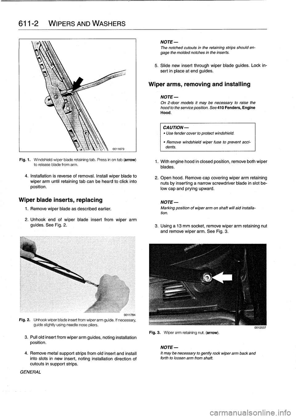
Fig
.
1
.
Windshield
wiper
biade
retaining
tab
.
Press
in
on
tab
(arrow)
to
release
bfade
from
arm
.
4
.
Installation
is
reverse
of
removal
.
Instan
wiperblade
to
wiper
arm
until
retaining
tab
can
be
heard
toclickinto
position
.
Wiper
biade
inserts,
replacing
1
.
Remove
wiper
blade
as
described
earlier
.
2
.
Unhook
end
of
wiper
blade
insert
fromwiper
arm
guides
.
See
Fig
.
2
.
0011784
Fig
.
2
.
Unhook
wiperbiade
insert
from
wiper
arm
guide
.
If
necessary,
guide
slightly
usingneed1e
nose
pliers
.
3
.
Pull
old
insert
fromwiper
arm
guides,
noting
installation
position
.
4
.
Remove
metal
support
strips
from
old
insert
and
instan
intoslots
in
new
insert,
noting
installation
direction
of
cutouts
in
support
strips
.
GENERAL
NOTE
-
The
notched
cutouts
in
the
retaining
strips
should
en-
gage
the
molded
notches
in
the
inserts
.
NOTE-
On
2-door
models
it
may
be
necessary
to
raise
the
hood
to
the
service
position
.
See
410
Fenders,
Engine
Hood
.
CAUTION-
"
Use
fender
cover
to
protect
windshield
.
"
Remove
windshield
wiper
fuse
to
prevent
acci-
dents
.
1.
With
engine
hood
in
closed
position,
remove
both
wiper
blades
.
2
.
Open
hood
.
Remove
cap
covering
wiper
arm
retaining
nutsby
inserting
anarrow
screwdriver
biade
in
slot
be-
low
capand
prying
upward
.
NOTE
-
Marking
position
of
wiper
arm
on
shaft
will
aid
installa-tion
.
3
.
Using
a13
mm
socket,
remove
wiper
arm
retaining
nut
andremove
wiper
arm
.
See
Fig
.
3
.
Fig
.
3
.
Wiper
arm
retaining
nut
.
(arrow)
.
,
NOTE
-
ft
may
benecessary
to
gently
rock
wiper
arm
back
and
forth
to
loosen
arm
from
shaft
.