vacuum BMW 318i 1995 E36 Owner's Manual
[x] Cancel search | Manufacturer: BMW, Model Year: 1995, Model line: 318i, Model: BMW 318i 1995 E36Pages: 759
Page 207 of 759
GENERAL
.
.
.......
.
......
.
...
.
.
.
.
.
...
180-1
Exhaust
system,
removing
and
installing
.
...
.180-3
EXHAUST
SYSTEM
REPLACEMENT
.
...
180-1
Exhaust
manifolds,
removing
and
installing
.
.
.180-5
GENERAL
The
exhaust
system
is
designed
to
be
maintenance
free,
al-
though
regular
inspection
is
warranted
due
to
the
harsh
oper-
atingconditions
.
Under
normal
conditions,
the
catalytic
converter
does
not
require
replacement
unless
it
is
damaged
.
On
1996
and
later
cars,
a
pre-
and
post-catalytic
converter
oxygen
sensor
is
used
at
each
catalytic
converter
.
Be
sure
to
take
care
when
removingthe
system
not
to
damage
the
sen-
EXHAUST
SYSTEMREPLACEMENT
sors
.
See
130
Fuel
Injection
for
information
on
testing
oxygen
sensors
.
NOTE-
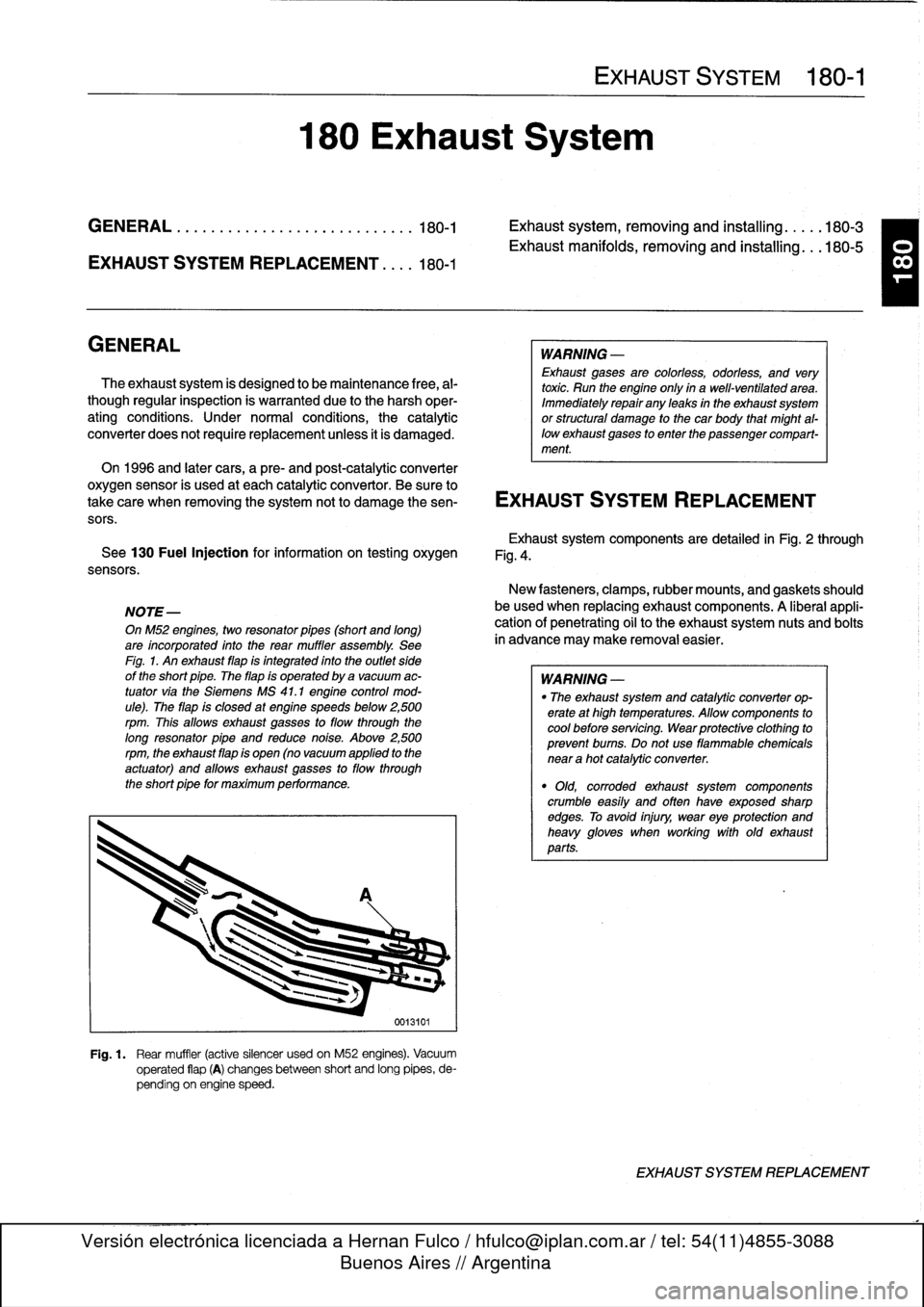
OnM52
engines,
two
resonator
pípes
(short
and
long)
are
incorporated
into
the
rear
muffler
assembly
.
See
Fíg
.
1
.
An
exhaust
flap
is
integrated
into
the
outlet
side
of
the
short
pipe
.
The
flap
is
operated
by
a
vacuum
ac-
tuator
via
the
Siemens
MS
41
.1
engine
control
mod-
ule)
.
The
flap
is
closed
at
engine
speeds
below
2,500
rpm
.
This
allows
exhaust
gasses
to
flow
through
the
long
resonator
pipe
and
reduce
noise
.
Above
2,500rpm,
the
exhaust
flap
is
open
(no
vacuum
applied
to
the
actuator)
and
allows
exhaust
gasses
to
flow
through
the
short
pipe
for
maximum
performance
.
180
Exhaust
System
0013101
Fig
.
1
.
Rear
muffler
(active
silencer
usedon
M52
engines)
.
Vacuum
operated
flap
(A)
changesbetween
short
and
long
pipes,
de-
pending
on
engine
speed
.
EXHAUST
SYSTEM
180-1
WARNING
-
Exhaust
gases
are
colorless,
odorless,
and
very
toxic
.
Run
the
engine
only
ín
a
well-ventilated
area
.
Immediately
repair
any
leaks
in
the
exhaust
system
or
structural
damage
to
the
car
body
that
might
al-
lowexhaust
gases
to
enter
the
passenger
compart-
ment
.
Exhaustsystem
components
are
detailed
in
Fig
.
2
through
Fig
.
4
.
New
fasteners,
clamps,rubber
mounts,
and
gaskets
should
be
used
when
replacing
exhaust
components
.
A
liberal
appli-
cationof
penetrating
oil
to
the
exhaustsystem
nuts
and
bolts
in
advance
may
make
removal
easier
.
WARNING
-
"
The
exhaust
system
and
catalytic
converter
op-
erate
at
high
temperatures
.
Allow
components
to
cool
before
servicing
.
Wear
protectíve
clothíng
to
prevent
bums
.
Do
not
use
flammable
chemicals
near
a
hot
catalytic
converter
.
"
Old,
corroded
exhaust
system
components
crumble
easíly
and
often
have
exposed
sharp
edges
.
To
avoid
injury,
wear
eye
protection
and
heavy
gloves
when
working
with
old
exhaust
parts
.
EXHAUST
SYSTEM
REPLACEMENT
T
Page 250 of 759
300-2
SUSPENSION,
STEERING
AND
BRAKES-GENERAL
Steering
INTEGRATED
SYSTEMS
The
steering
linkage
connects
the
rack-and-pinion
unit
through
tie
rodsto
the
steering
arms
.
The
tie
rod
ends
allow
the
wheels
to
pivot
and
react
to
suspension
travel
.
Rear
Suspension
The
rear
axle
carrier
is
the
main
mounting
point
for
the
final
drive
housing
and
the
rear
suspension
components
.
Trailing
arms
locatethe
rear
wheels
and
anchorthe
springs,
shocks
and
stabilizer
bar
.
Driveaxies
with
constant-velocity
(CV)
joints
at
both
ends
transfer
power
from
the
differential
to
the
road
wheels
.
The
differential
is
mounted
to
the
rearaxle
carrier
through
rubber
mountsand
bushings
to
hele
isolate
drivetrain
noise
and
vibration
.
Brakes
E36
cars
areequipped
with
power
disc
brakes
with
an
inte-
gral
antilock
brakes
(ABS)
.
The
parking
brake
is
a
dual-drum
system
integrated
with
the
rear
brake
rotors
.
See
Fig
.
3
.
Power
assist
is
provided
by
a
vacuum
booster
when
the
en-
gine
is
running
.
The
brakepedal
pushrod
is
connected
directly
to
the
master
cylinder,
so
failure
of
the
vacuum
booster
does
not
normally
result
in
total
brake
failure
.
0012124
Each
disc
brakeuses
a
caliper
with
a
single
hydraulic
cylin-
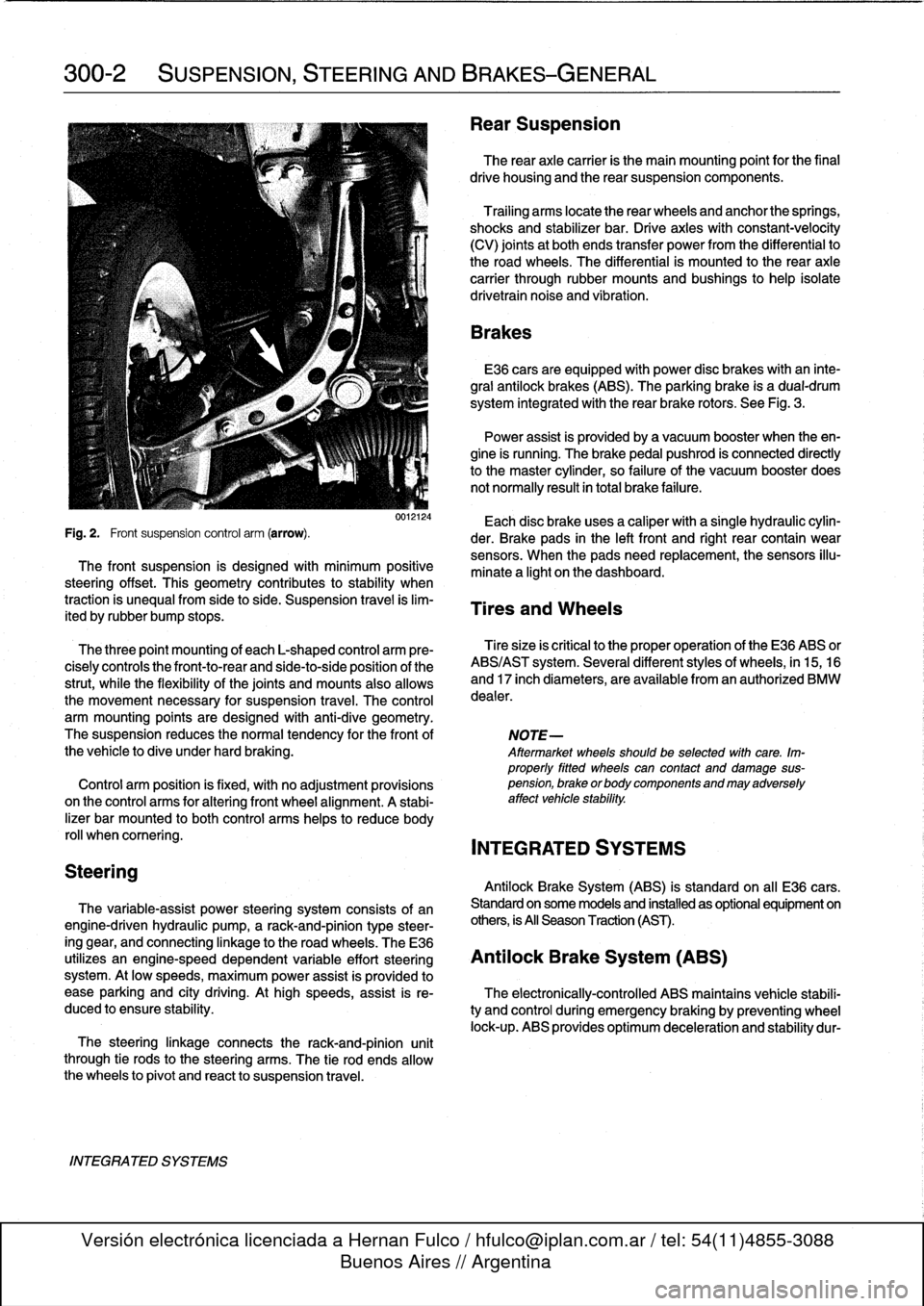
Fig
.
2
.
Front
suspension
control
arm
(arrow)
.
der
.
Brake
pads
in
the
left
front
and
right
rear
contain
wear
sensors
.
When
the
padsneed
replacement,the
sensors
illu-
The
front
suspension
is
designed
with
minimum
positive
minate
a
light
on
the
dashboard
.
steering
offset
.
This
geometry
contributes
to
stability
when
traction
is
unequalfrom
side
to
side
.
Suspension
travel
is
lim-
Tires
and
Wheels
ited
by
rubber
bump
stops
.
The
three
point
mounting
of
each
L-shaped
control
arm
ere-
Tiresize
is
critica¡
to
the
proper
operatíon
of
the
E36
ABS
or
cisely
controls
the
front-to-rear
and
side-to-side
position
of
the
ABS/AST
system
.
Severa¡
different
styles
of
wheels,
in
15,16
strut,
while
the
flexibility
of
the
joints
and
mounts
alsoallows
and
17
inch
diameters,
are
available
from
an
authorized
BMW
the
movement
necessary
for
suspension
travel
.
The
control
dealer
.
arm
mounting
points
are
designed
with
anti-dive
geometry
.
The
suspension
reduces
the
normaltendency
for
the
front
of
NOTE-
the
vehicle
to
dive
under
hard
braking
.
Aftermarket
wheelsshould
be
selected
wlth
care
.
Im-
properly
fitted
wheels
can
contact
anddamage
sus
Control
arm
position
is
fixed,
with
no
adjustment
provisions
pension,
brakeorbodycomponentsandmayadversely
on
the
control
arms
for
alter¡ng
front
wheel
al
ignment
.
A
stabi-
affect
vehicle
stability
.
lizer
bar
mounted
to
both
control
arms
heles
to
reduce
body
rol¡
whencomering
.
INTEGRATED
SYSTEMS
Antilock
Brake
System
(ABS)
is
standard
on
all
E36
cars
.
The
variable-assist
power
steering
system
consists
of
an
Standard
on
some
models
and
installed
as
optional
equipment
on
engine-driven
hydraulic
pump,
a
rack-and-pinion
type
steer-
others,
is
All
Season
Traction
(AST)
.
ing
gear,
and
connecting
linkage
to
the
road
wheels
.
TheE36
utilizes
an
engine-speed
dependent
variable
effort
steering
Antilock
Brake
System
(ABS)
system
.
At
low
speeds,
maximum
power
assist
is
provided
to
ease
parking
and
city
driving
.
Athigh
speeds,
assist
is
re-
The
electronically-controlled
ABS
maintains
vehícle
stabili
duced
to
ensure
stability
.
ty
and
control
during
emergency
braking
by
preventing
wheel
lock-up
.
ABS
provides
optimum
deceleration
and
stability
dur-
Page 291 of 759
Brake
rotor,
removing
and
installing
.
.
.
.
.
.
.
.
340-7
MASTER
CYLINDER
............
.
.
.
.
.
.
.340-7
Master
cylinder,
removing
and
installing
.
...
.
340-7
GENERAL
TROUBLESHOOTING
WARNING
-
"
Although
semi-metallic
and
metallic
Brake
friction
materials
in
Brake
pads
or
shoes
no
longer
con-
tain
asbestos,
they
produce
dangerous
dust
.
"
Brake
fluid
is
poisonous,
highly
corrosive
and
dangerous
to
the
environment
Wear
safety
glasses
and
rubber
gloves
when
working
with
Brake
fluid
.
Do
not
siphonBrake
fluid
with
your
mouth
.
Immediately
clean
away
any
fluid
spilled
on
painted
surfaces
and
wash
with
water,
asBrake
fluid
will
remove
paint
.
"
Always
use
new
Brake
fluid
froma
fresh,
un-
opened
container
.
Brake
fluid
will
absorb
mois-
ture
from
the
air
.
This
canlead
to
corrosion
problems
in
the
brakingsystem,
and
will
also
low-
er
the
Brake
fluid's
boiling
point
.
Dispose
of
Brake
fluid
properly
.
"
Do
notreuse
self-locking
nuts,bolts
or
fasteners
.
They
are
designed
to
be
used
only
once
and
may
failif
reused
.
Always
replace
them
with
new
self-
locking
fasteners
.
BMW
E36
models
areequipped
with
vacuum
power-assist-
ed
four-wheel
disc
brakes
with
an
integral
Antilock
Brake
Sys-
tem
(ABS)
.
Single-pistoncalipers
act
on
solid
or
vented
front
rotors
and
solid
rear
rotors
.
A
brake
pad
wear
sensor
for
each
axle
indicates
when
brake
padsneed
replacement
.
The
dual
drum-type
parking
brakesystem
is
integrated
with
the
rear
brake
rotors
.
NOTE-
M3
models
havevented
directional
Brake
rotors
on
the
rearaxle
as
well
ason
the
front
.
340
Brakes
BRAKES
340-1
GENERAL
.
.
.
.
.
.
.........
.
.
.
..........
340-1
BRAKE
BOOSTER
.........
.
.
.
.
.
...
.
.
.
.
340-8
TROUBLESHOOTING
.......
.
......
.
...
340-1
Brake
booster,
removing
and
installing
....
.
.
340-8
PARKING
BRAKE
.
.....
.
...
.
.
.
.....
.
.
.
340-10
BLEEDING
BRAKES
.
.
.
.
.
.
.
.
..........
340-3
Parking
brake,adjusting
.
.
.
.
.
.
.
.
.
.
.....
.
340-10
Pressure
bleeding
brakes
Parking
brake
shoes,
removing
and
installing
.
340-11(except
cars
with
AST)
.
.
.
.
.
.
.
.
.
...
.
.
.
.
.340-3
Parking
Brake
cable,
replacing
.
.
.
.
.
.
.
.
.
.
.
.
340-11
BRAKE
PADS,
CALIPERS,
ANTILOCK
BRAKE
SYSTEM
(ABS)
.
.
.
.340-11
AND
ROTORS
..........
.
.......
.
.
.
.
.
.
.
340-3
ABS
System
Inspection
.
...
.
.......
.
.
.
..
340-12
Brake
pads,
replacing
............
.
.
.
.
.
.
.
340-4
ABS
wheel
speed
sensors,
replacing
.
.
.
.
..
340-12
Brake
caliper,
removing
and
installing
.
..
..
.
340-6
TABLES
a
.
Brake
System
Troubleshooting
.....
...
.
.
.....
.340-2
b
.
Brake
Rotor
Reconditioning
Specifications
.
.....
.340-7
Brakeperformance
is
mainly
affected
by
three
things
:
the
leve¡
and
condition
of
the
brake
fluid,
the
system's
abilíty
to
create
and
maintain
hydraulic
pressure,
and
the
condition
of
the
friction
components
.
Air
in
the
Brake
fluid
will
make
the
Brake
pedal
feel
spongy
during
braking
or
will
increase
the
Brake
pedalforce
required
to
stop
.
Fluid
contaminated
by
moisture
or
dirt
can
corrode
the
system
.
Inspect
the
Brake
fluid
inside
the
reservoir
.
Ifit
is
dirty
or
murky,
or
is
over
a
year
old,
the
fluid
should
be
replaced
.
Visually
check
the
hydraulic
system
startingat
the
master
cylinder
.
To
check
the
function
of
the
master
cylinder
hold
the
brake
pedal
down
hard
with
the
engine
running
.
The
pedal
should
feelsolid
and
stay
solid
.
If
the
pedal
slowly
falls
to
the
floor,
either
the
master
cylinder
is
leaking
internally,
or
fluid
is
leaking
externally
.
If
no
leaks
canbe
found,
the
master
cylin-
der
is
faulty
and
should
be
replaced
.
Check
all
Brake
fluid
lines
and
couplings
for
leaks,
kinks,
chafing
and
corrosion
.
Check
the
Brake
booster
by
pumping
the
Brake
pedal
ap-
proximately
10
times
with
the
engine
off
.
Hold
the
pedal
down
and
start
the
engine
.
The
pedal
should
fa¡¡
slightly
.
If
not,
check
for
any
visiblefaults
before
suspecting
a
faulty
brake
booster
.
Check
for
strong
vacuum
at
the
vacuum
hose
fitting
at
the
booster,
and
check
the
non-retum
valve
for
one-way
flow
.
Worn
or
contaminated
brake
pads
will
cause
poor
braking
performance
.
Oil-contaminated
or
glazed
pads
will
cause
stopping
distances
to
increase
.
Inspect
the
rotors
for
glazing,
discoloration
and
scoring
.
Steering
wheel
vibration
while
braking
at
speed
is
often
caused
by
warped
rotors,
but
can
also
be
caused
byworn
suspension
components
.
TROUBLESHOOTING
Page 292 of 759
340-2
BRAKES
When
troubleshooting,
keep
in
mind
that
tire
inflation,
wear
and
temperature
can
affect
braking
and
suspension
.
See310
Front
Suspension
for
more
information
on
front
suspension
parts
inspection
.
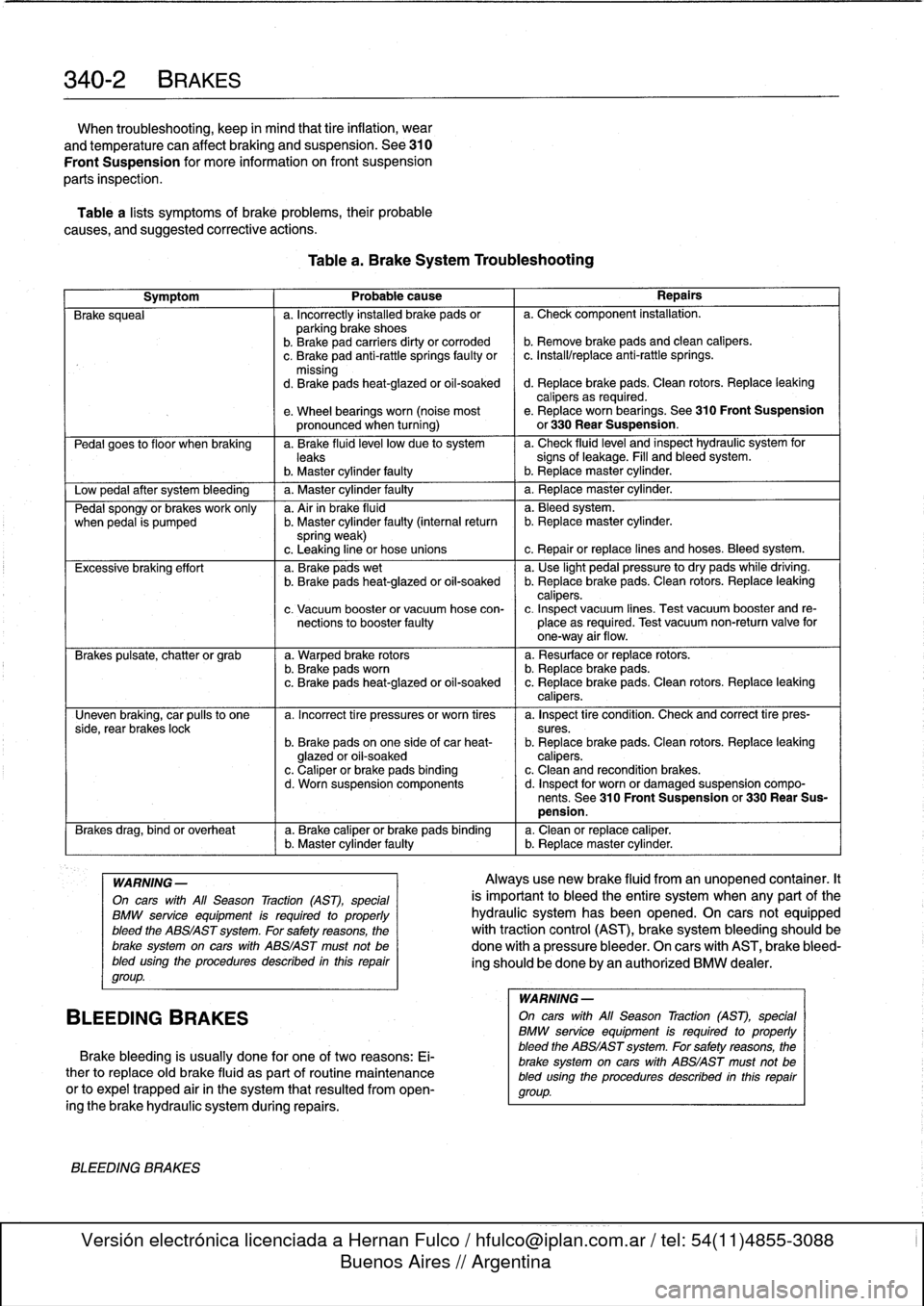
Table
a
lists
symptoms
of
brake
problems,
their
probable
causes,
and
suggested
corrective
actions
.
Table
a
.
Brake
System
Troubleshooting
Symptom
1
Probable
cause
1
Repairs
Brake
squeal
a
.
Incorrectly
installed
brake
pads
or
a
.
Check
component
installation
.
parking
brake
shoes
b
.
Brakepad
carriers
dirty
or
corroded
b
.
Remove
brake
pads
and
clean
calipers
.
c
.
Brake
pad
anti-rattle
springs
faulty
or
c
.
Install/replace
anti-rattle
springs
.
missing
d
.
Brakepads
heat-glazed
or
oil-soaked
d
.
Replace
brake
pads
.
Clean
rotors
.
Replace
leaking
calipers
as
required
.
e
.
Wheel
bearings
worn
(noise
most
e
.
Replace
worn
bearings
.
See310
Front
Suspension
pronounced
when
turning)
or
330
Rear
Suspension
.
Pedal
goes
to
f
loor
when
braking
a
.
Brake
fluid
leve¡
low
due
to
system
a
.
Check
fluidlevel
and
inspect
hydraulic
system
for
leaks
signs
of
leakage
.
Fill
and
bleed
system
.
b
.
Master
cylinder
faulty
I
b
.
Replacemaster
cylinder
.
Low
pedal
after
system
bleeding
1
a
.
Master
cylinder
faulty
1
a
.
Replace
master
cylinder
.
Pedal
spongy
or
brakes
work
only
a
.
Air
in
brake
fluid
a
.
Bleedsystem
.
when
pedal
is
pumped
b
.
Master
cylinder
faulty
(interna¡
return
b
.
Replacemaster
cylinder
.
spring
weak)
c
.
Leaking
line
or
hose
unions
c
.
Repair
or
replace
lines
and
hoses
.
Bleed
system
.
Excessive
braking
effort
a
.
Brake
pads
wet
a
.
Use
light
pedal
pressure
to
dry
pads
while
driving
.
b
.
Brake
pads
heat-glazed
oroil-soaked
b
.
Replace
brake
pads
.
Clean
rotors
.
Replace
leaking
calipers
.
c
.
Vacuum
booster
or
vacuum
hose
con-
c
.
Inspect
vacuum
lines
.
Test
vacuum
booster
and
re
nections
to
booster
faulty
place
as
required
.
Test
vacuum
non-return
valve
for
one-way
air
flow
.
Brakes
pulsate,
chatter
or
grab
a
.
Warped
brake
rotors
a
.
Resurface
or
replace
rotors
.
b
.
Brake
padsworn
b
.
Replace
brake
pads
.
c
.
Brake
pads
heat-glazed
or
oil-soaked
c
.
Replace
brake
pads
.
Clean
rotors
.
Replace
leaking
calipers
.
Uneven
braking,
car
pulís
to
one
a
.
Incorrect
tire
pressures
or
worn
tires
a
.
Inspect
tire
condition
.
Check
and
correct
tire
pres-
side,
rear
brakes
lock
sures
.
b
.
Brake
pads
on
one
side
of
car
heat-
b
.
Replace
brake
pads
.
Clean
rotors
.
Replace
leaking
glazed
or
oil-soaked
calipers
.
c
.
Caliper
or
brake
pads
binding
c
.
Clean
and
recondition
brakes
.
d
.
Worn
suspension
components
d
.
Inspect
for
worn
or
damaged
suspension
compo-
nents
.
See
310
Front
Suspension
or
330
Rear
Sus-
pension
.
Brakes
drag,
bind
or
overheat
a
.
Brake
caliper
or
brake
pads
binding
a
.
Clean
or
replace
caliper
.(
b
.
Master
cylinder
faulty
b
.
Replacemaster
cylinder
.
WARNING
-
On
cars
with
All
Season
Traction
(AST),
special
BMW
service
equipment
is
required
to
properly
bleed
the
ABS/AST
system
.
For
safety
reasons,
the
brake
system
on
carswith
ABS/AST
must
not
be
bled
using
the
procedures
described
inthis
repair
group
.
BLEEDING
BRAKES
Brake
bleeding
is
usually
done
for
one
of
two
reasons
:
Ei-
ther
to
replace
oíd
brake
fluid
as
part
of
routine
maintenance
or
to
expel
trapped
air
in
the
system
that
resulted
from
open-
ingthe
brake
hydraulic
system
during
repairs
.
BLEEDING
BRAKES
Alwaysuse
new
brake
fluid
from
an
unopened
container
.It
is
important
to
bleed
the
entire
system
when
any
part
of
the
hydraulic
system
has
been
opened
.
On
cars
not
equipped
with
traction
control
(AST),
brake
system
bleeding
should
be
done
with
a
pressure
bleeder
.
On
cars
with
AST,
brake
bleed-
ing
should
be
done
by
an
authorized
BMW
dealer
.
WARNING
-
On
cars
with
All
Season
Traction
(AST),
special
BMW
service
equipment
is
requíred
to
properly
bleed
the
ABS/AST
system
.
For
safetyreasons,
the
brake
system
on
carswith
ABS/AST
must
not
be
bled
using
the
procedures
described
inthís
repair
group
.
Page 298 of 759
340-
8
BRAKES
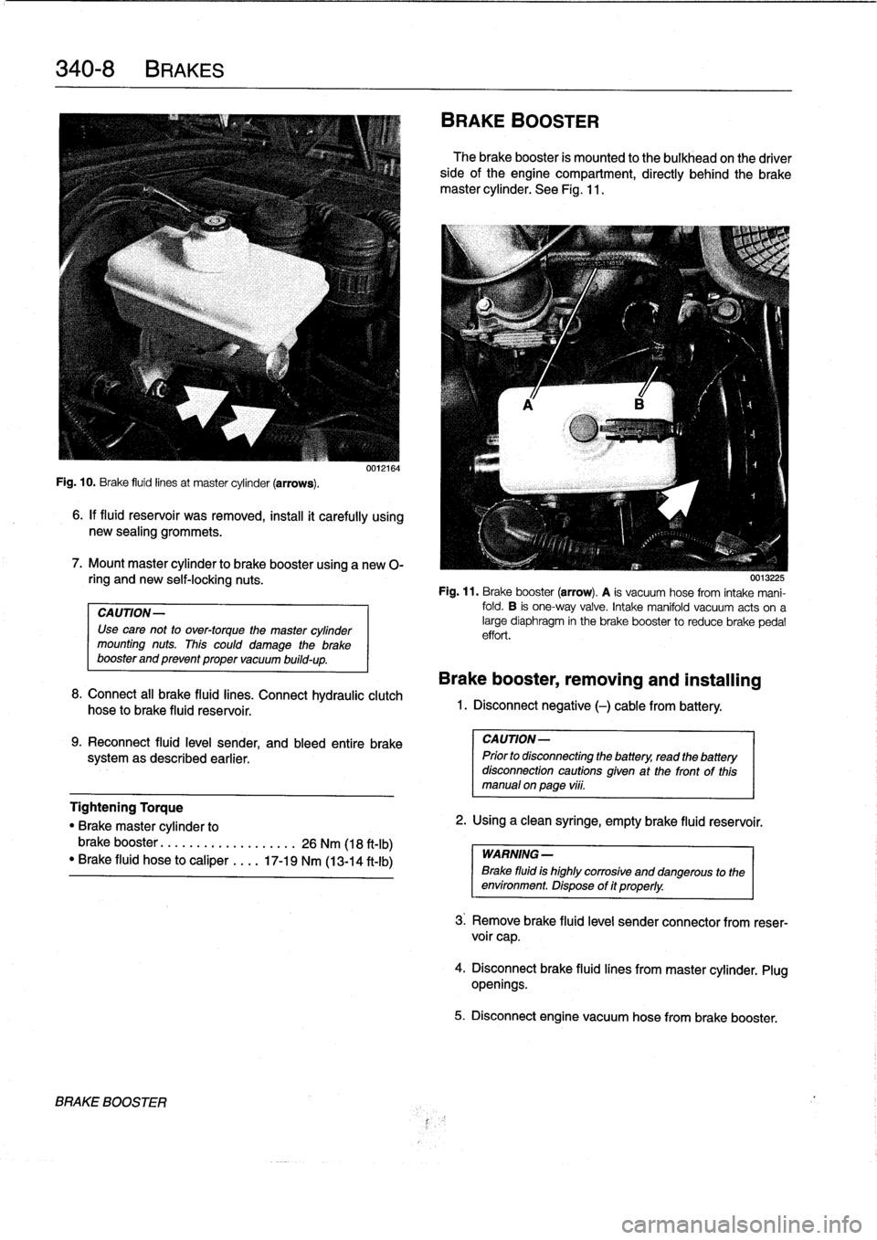
Fig
.
10
.
Brake
fluid
linesat
master
cylinder
(arrows)
.
6
.
If
fluid
reservoir
was
removed,
install
it
carefully
using
new
sealing
grommets
.
7
.
Mount
master
cylinder
to
brake
booster
using
a
new
0-
ring
and
new
self-locking
nuts
.
CAUTION-
Use
cave
not
to
over-torque
the
master
cylinder
mounting
nuts
.
This
could
damage
the
brake
booster
and
prevent
proper
vacuum
build-up
.
0012164
8
.
Connect
all
brake
fluid
lines
.
Connect
hydraulic
clutch
hose
to
brake
fluid
reservoir
.
9
.
Reconnect
fluid
leve¡
sender,
and
bleed
entire
brake
systemas
described
earlier
.
BRAKE
BOOSTER
BRAKE
BOOSTER
The
brake
booster
is
mounted
to
the
bulkhead
on
the
driver
sideofthe
engine
compartment,
directly
behind
the
brake
master
cylinder
.
See
Fig
.
11
.
0015225
Fig
.
11
.
Brake
booster
(arrow)
.
A
is
vacuum
hose
from
intake
mani-
fold
.
B
is
one-way
valve
.
Intake
manifold
vacuum
acts
ona
large
diaphragm
in
the
brake
booster
to
reducebrake
pedal
effort
.
Brake
booster,
removing
and
installing
1
.
Disconnect
negative
(-)
cable
from
battery
.
CAUTION-
Prior
to
disconnecting
the
battery,
read
the
battery
disconnection
cautions
given
at
the
front
of
this
manual
onpage
vi¡¡
.
Tightening
Torque
"
Brake
master
cylinder
to
2
.
Using
a
clean
syringe,
empty
brake
(luid
reservoir
.
brake
booster
.....
..
.
..
.........
26
Nm
(18
ft-Ib)
WARNING-
"
Brake
fluid
hose
to
caliper
....
17-19
Nm
(13-14
ft-Ib)
Brake
fluid
is
highly
corroslve
and
dangerous
to
the
environment
.
Dispose
of
it
properly
.
3
.
Remove
brake
fluid
level
sender
connector
from
reser-
voir
cap
.
4
.
Disconnectbrake
fluid
lines
from
master
cylinder
.
Plug
openings
.
5
.
Disconnect
engine
vacuum
hose
from
brake
booster
.
Page 299 of 759
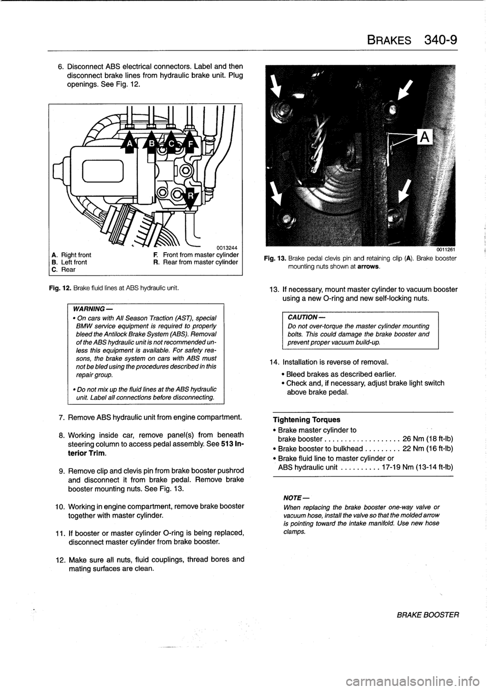
6
.
Disconnect
ABS
electrical
connectors
.
Label
and
then
disconnect
brake
lines
from
hydraulic
brake
unit
.
Plug
openíngs
.
See
Fig
.
12
.
~
~
A
1/
B
'1v
C
~
F
lu
11
-ri
J
.
0013244
A
.
Right
front
F
Front
from
master
cylinder
B
.
Leftfront
R
.
Rear
from
master
cylinder
C
.
Rear
Fig
.
12
.
Brake
fluid
linesat
ABS
hydraulic
unit
.
WARNING
-
"
On
cars
with
All
Season
Traction
(AST),
special
BMW
service
equipment
is
required
to
properly
bleed
the
Antilock
Brake
System
(ABS)
.
Removal
of
the
ABS
hydraulic
unit
is
not
recommended
un-
less
this
equipment
is
available
.
For
safetyrea-
sons,
the
brake
system
on
cars
with
ABS
must
not
be
bled
using
the
procedures
described
inthis
repair
group
.
"
Do
not
mix
up
the
fluid
fines
at
the
ABS
hydraulic
unit
Label
all
connections
before
disconnecting
.
7
.
Remove
ABS
hydraulic
unit
from
engine
compartment
.
8
.
Working
inside
car,
remove
panel(s)
frombeneath
steering
column
to
access
pedal
assembly
.
See513
In-
terior
Trim
.
12
.
Make
sure
al¡
nuts,
fluid
couplings,
thread
bores
and
mating
surfaces
are
clean
.
BRAKES
340-
9
0011261
Fig
.
13
.
Brake
pedal
clevispin
and
retaining
clip
(A)
.
Brake
booster
mounting
nuts
shown
at
arrows
.
13
.
If
necessary,
mount
master
cylinder
to
vacuum
booster
using
a
new
O-ríng
and
newself-locking
nuts
.
CAUTION-
Do
not
over-torque
the
master
cylinder
mounting
bolts
.
This
could
damage
the
brake
booster
and
prevent
proper
vacuum
build-up
.
14
.
Installation
is
reverse
of
Rmoval
.
"
Bleed
brakes
as
described
earlier
.
"
Check
and,
if
necessary,
adjust
brake
light
switch
above
brake
pedal
.
Tightening
Torques
"
Brakemaster
cylinder
to
brake
booster
...........
.
..
..
...
26
Nm
(18
ft-Ib)
"
Brake
booster
to
bulkhead
.
.
..
..
...
22
Nm
(16
ft-Ib)
"
Brake
fluidline
to
master
cylinder
or
ABS
hydraulic
unit
.......
.
..
17-19
Nm
(13-14
ft-lb)
9
.
Remove
clip
and
clevis
pin
from
brake
booster
pushrod
and
disconnect
it
from
brakepedal
.
Remove
brake
booster
mounting
nuts
.
See
Fig
.
13
.
NOTE-
10
.
Working
in
engine
compartment,
remove
brake
booster
When
replacing
the
brake
booster
one-way
valve
or
together
with
master
cylinder
.
vacuum
hose,
install
the
valve
so
that
the
molded
arrow
is
pointing
toward
the
intake
manifold
.
Use
new
hose
11
.
If
booster
or
master
cylinder
O-ring
is
being
replaced,
clamps
.
disconnect
master
cylinder
from
brake
booster
.
BRAKE
BOOSTER
Page 331 of 759
GENERAL
......
.
........
.
.
.
.
.
.
.
...
.
.
.
512-1
WINDOW
SERVICE,
Front
door
window,
initializing
..
.
.........
.
512-1
2-DOOR
MODELS
.
...
.
......
.
........
.512-5
WINDOW
SERVICE,
Front
door
window,
removing
and
installing
(2-door
models)
.
.
...
.
...............
.
512-5
4-DOOR
MODELS
.
.
.
.
................
.
512-2
Front
door
window,
adjusting
Front
door
window,
removing
and
installing
(2-door
models)
.
.
.
.
.
.
.........
.
.
.
...
.512-7
(4-door
models)
.
.
.
.
.
...
.
.
.
.
.
.
.
.
.
.....
512-2
Rear
vent
window
or
vent
latch,
Front
door
window,
adjusting
replacing
(2-door
models)
....
.
.
.
.
.
.
.
...
512-11
(4-door
models)
.
.
.
.
.
...
.
...
.
.
.
.
.
.....
512-3
Rear
door
window,
removing
and
installing
WINDOW
REGULATOR
SERVICE
.
.
.
..
.512-12
(4-door
models)
.
.
.
.....
.
.
.
.
...
.
.
.....
512-4
Door
window
regulator
and
motor,
Rear
door
fixed
glass,
removing
and
installing
removing
and
installing
.
.
.
...
.
.
.
.
.
.
.
.
.
.
512-12
(4-door
models)
.
.
.
.
.
...
.
.
.
.
.
.
.
.
.
.....
512-4
GENERAL
Front
door
window,
initializing
This
heading
covers
door
glass,
window
regulator
and
pow-
er
window
motor
repair
information
.
Before
proceeding
with
window
repairs,
specifically
on
late
cars
fitted
with
front
side-
impact
airbags,
read
the
procedure
through
to
determine
the
scope
of
the
repair
.
The
bonded
windshield
and
rear
glass
are
replaced
using
special
adhesives
and
tools
.
It
is
recommended
that
bonded
glass
replacement
bedone
by
a
professional
glass
installer
.
WARNING
-
"
Always
wear
hand
and
eye
protection
when
workíng
with
broken
glass
.
"
ff
a
window
is
broken,
all
of
the
glass
bits
should
be
vacuumed
out
of
the
door
cavity
.
Use
a
blunt
screwdriver
to
clean
out
any
remaining
glass
pieces
from
the
window
guide
rails
.
CAUTION-
ff
battery
power
is
lost
or
the
battery
has
been
dis-
connected,
windows
mustbe
re-initialized
.
Both
one
touch
up/down
and
pinch-protection
will
be
in-
active
until
windows
are
re-initialized
.
Sea
below
.
512
Door
Windows
DOOR
WINDOWS
512-1
The
front
door
windows
incorporate
a
pinch-protection
fea-
ture
as
well
as
one-touch
up/down
(1994
and
later
models)
.
In
order
for
these
featuresto
work
correctly,
the
mechanical
stop
reference
point
must
be
re-initialized
after
repairs
are
carried
out
.
1
.
Closedoor
and
turn
ignition
keyon
.
Fully
open
front
window
.
2
.
Fully
close
front
window
.
4
.
Repeat
for
remaining
window
.
5
.
The
windows
should
now
be
initialized
and
the
anti-
pinch
and
one-touch
up/down
functions
should
be
en-
abled
.
GENERAL
Page 752 of 759
WARNING
Your
common
sense,
good
judge-
ment,
and
general
alertness
are
cru-
cial
to
safe
and
successful
service
work
.
Befcre
attempting
any
work
on
your
BMW,
read
the
warnings
and
cautions
on
page
vi¡
and
the
copyright
page
at
the
frontof
the
manual
.
Review
these
warnings
and
cautions
each
time
you
prepare
to
workon
your
BMW
.
Please
also
read
any
warnings
and
cautions
that
accom-
pany
the
procedures
in
the
manual
.
Door
glass
See
Door
windows
Door
windows
general
information
512-1
front
door
window
(2-door
models)
adjusting
512-7
removing/installing
512-5
front
door
window
(4-door
models)
initíalizing
512-1
removing/installing
512-2
rear
door
window
(4-door
models)
removing/installing
512-4
fixed
glass,
removing/installing
512-
4
rear
vent
window
or
vent
latch,
replacing
(2-door
models)
512-11
window
regulator
and
motor,
removing/installing
512-12
window
regulator
service
512-12Doorcheck
See
DoorsDoor
handle
See
Centrallocking
and
anti-theft
Door
panel
See
Doors
Doors
general
information
411-1
door
adjustment
411-2door
check,
replacing
411-2
door
panels
411-3
doors411-1
front
orrear
door,removing/installing
411-1
front
door
panel,
removing/installing
411-3
rear
door
panel,
removing/installing
411-4
rearsidepanel,
removing/installing
(two-door
model)
411-4
Drive
axle
See
Rear
suspension
Driveability
troubleshooting
See
Engine-general
Driveshaft
general
information
260-1
center
bearing
assembly,
replacing
260-6
driveshaft,
aligning
260-3
driveshaft,
installing
260-4
Driveshaft
(cont
.)
driveshaft,
removing260-4
driveshaftservice
260-3
flex-disc,
replacing
260-5
front
centering
guide,
replacing
260-7
guibo
See
flex-disc
troubleshooting260-1
ECM
(engine
control
module)
pin
assignment
See
Fuel
injection
Electrical
circuit
See
Electrical
system-general
Electrical
component
locations
general
information
610-1
auxíliary
relay
panel
610-2
component
location
table
610-9
component
locations
610-3
fuse
position
tables
610-19
fuse
positions
610-1
relay
positions
610-2
splice
panel,
left
610-2
splice
panel,
right
610-3
Electrical
system-general
general
information
600-1
continuity,
checking
600-5
electrical
test
equipment
600-2
safety
precautions
600-1
short
circuits
600-5
short
circuit,
testing
with
ohmmeter
600-6
short
circuit,
testing
with
voltmeter
600-6
troubleshooting
600-3
voltage,
measuring600-4
voltage
and
polarity
600-1
voltage
and
voltage
drops
600-4
voltage
drop,
testing
600-4
wiring
codes
and
abbreviations
600-2
wiring
diagrams
600-2
wiring,
fuses
and
relays
600-1
Electrical
wiring
diagrams
general
information
ELE-1
wiring
diagrams
ELE-2
ABS
ELE-117
ABS/AST
ELE-120
airbag
(supplemental
restraint
system)
ELE-140
air
conditioning
and
heating
ELE-
129
anti-theft
(Alpine)
system
ELE-144
anti-theft
(EWS
II)
ELE-150
body
computer
module
ELE-176
charging
system
ELE-67
convertible
top
ELE-253
cruise
control
ELE-112
data
link
connector
ELE-86
engine
cooling
ELE-94
engine
management
ELE-70
exterior
lights
ELE-194
ground
distribution
ELE-35
headlights/foglights
ELE-180
INDEX
3
Electrical
wiring
diagrams
(cont
.)
heated
seats
ELE-245
horns
ELE-153
instrument
panel
ELE-165
interior
lights/illumination
ELE-211
lumbar
control
ELE-247
on-board
computer
ELE-173
park
ventilation
ELE-139
power
distribution
ELE-2
power
door
locks
ELE-226
power
mirrors
ELE-241
power
seats
ELE-243
power
sunroof
ELE-248
power
windows
ELE-231
radio/cassette/CD/speakers
ELE-
255
rear
window
defogger
ELE-160
shift
interlock
ELE-110
starting
ELE-63
transmission
electronics
ELE-96
warning
systems`
.
chimes
ELE-178
wiper/washer
ELE-154
Emergencies
See
Fundamentals
for
the
do-it-
yourself
owner
Engine-general
general
information
100-1
air
flow
measurement
and
vacuum
leaks
100-12
basic
engine
settings
100-11
basic
requirements
100-11
battery
voltage
100-12connecting
rods
and
pistons
100-1
cooling
system
100-5
cylinder
block
and
crankshaft100-1
cylinder
compression,
checking
100-6
cylinder
head
and
valvetrain
100-2
DISA
(dual
resonance
intake
system)
100-3,130-3
driveability
troubleshooting
100-8
engine
management
system
100-3
fuel
delivery
100-5
fuel
supply
100-14ground
connections
100-13
ignition
100-5
lubrication
system100-5
mechanical
troubleshooting
100-5
on-board
diagnostics
(OBD)
100-8
oxygen
sensors
100-11
preventive
maintenance
100-11
VANOS
(variable
valve
timing)
100-2warningsand
cautions
100-5
wiring
andharness
connections100-
13Engine
control
module
(ECM)
See
Fuel
injection
Engine
removal
and
installation
general
information
110-1
engine,
removing/installing(4-cylinder
engines)
110-1
engine,
removing/installing
(6-cylinder
engines)
110-4
Engine
coolant
temperature
(ECT)
sensor
See
Fuel
injection
Engine
hood
See
Fenders,
enginehood
Page 757 of 759
8
INDEX
Speakers
See
Radio
SRS
(Supplemental
restraint
system)
See
Airbag
system
(SRS)
Starter
See
Battery,
starter,
alternator
Steering
and
wheel
alignment
general
information
320-1
caster
and
camber
320-5
front
toe-in
and
toe
difference
angle
320-6
outer
tie
rod
end,
replacing
320-4
power
steering
pump,
removing/
installing
320-2
power
steering
system
320-2
power
steering
system,
bleeding/filling
320-3
rear
toe-in
320-6
steering
gear320-3
steering
gear
rack,
removing/installing
320-3
steering
wheel
320-1
steering
wheel,
removing/installing
320-1
tie
rod,
replacing
320-5
wheel
alignment
320-5
wheel
alignment
specifications
320-6
Steering
gear
See
steering
and
wheel
alignment
Strut
See
Front
suspension
Subframe
See
Front
suspension
Sunroof
general
information
540-1
motor,
removing/installing
540-3
panel,
adjusting
540-2
panel,
emergency
closing
540-2
Suspension,
front
See
Front
suspension
Suspension,
rear
See
Rear
suspension
Suspension,
steering
and
brakes
general
information
300-1
al¡
season
traction
(AST)
300-4
antilock
brake
system
(ABS)
300-2
brakes
300-2
front
suspension
300-1
integrated
systems
300-2
M3
suspension
and
brakes
300-7
steering
300-2
rear
suspension
300-2suspension
and
steering
troubleshooting
300-7
tires
and
wheels300-2
T
Switches
and
electrical
accessories
general
information
612-1
dome
light,
rear
map
lights,
trunk
light,
replacing
bulbs
612-7
hazard
warning
switch,
replacing
612-5
headlight
switch,
replacing
612-5
foglight
switch,
replacing
612-5
ignition
electrical
switch,
replacing
612-3
ignition
lock
cylinder,
replacing
612-4
ignition
switch
assembly
612-3
outside
mirror
switch,
replacing
612-6
power
window
switch,
replacing
612-5
turn
signal
switch
and
wiper
switch,
removing/installing
612-1
wiper
switch
See
turn
signal
and
wiper
switch
Taillight
See
Exterior
lighting
Thermostat
See
Cooling
system
Throttleposition
sensor
(TPS)
See
Fuel
injection
Throw-out
bearing
See
ClutchTierod
See
Steering
and
wheel
alignment
Tires
See
Suspension,
steering
and
brakes-general
See
also
Maintenance
program
Timing
chain
See
Camshaft
timing
chain
Toe-in
See
Steering
and
wheel
alignment
Tools
See
Fundamentals
for
the
do-it-
yourself
owner
Torque
convector
See
Automatic
transmission
Towing
See
Fundamentals
for
the
do-it-
yourself
owner
Traction
control
See
also
Suspension,
steering
and
brakes-general
Trailing
arm
See
Rear
suspension
Transmission-general
See
also
Automatic
transmission
See
also
Manual
transmission
general
information
200-1
automatic
transmission
200-1
manual
transmission
200-1
transmission
ID
codes
200-2
Transmission
fluid
See
Maintenance
program
See
also
Automatic
transmission
Transmission
input
shaft
See
Manual
transmission
Transmission
output
shaft
See
Manual
transmission
Trim,
interior
See
Interior
trim
Trunk
lid
general
information
412-1
trunk
lid,
412-1
trunk
lid,
aligning
412-1
trunk
lid,
removing/installing
412-1
trunk
lid
support
strut,
removing/
installing
412-2
U
Upholstery
See
Maintenance
program
U-joints
See
Driveshaft
V
V-belt
See
Maintenance
program
Vacuum
booster
See
Brakes
Vacuum
leaks
See
Engine-general
Valveguides
See
Cylinder
head
and
valvetrain
Valve
seals
See
Cylinder
head
and
valvetrain
Valveseats
See
Cylinder
head
and
valvetrain
Valves
See
Cylinder
head
and
valvetrain
Valvetrain
See
Cylinder
head
and
valvetrain
VANOS
(variable
valve
timing)
See
Camshaft
timing
chaín
See
also
Engine-general
Vehicle
identification
number
(VIN)
See
Fundamentals
for
the
do-it-
yourself
owner
Vehicle
speed
sensor
See
Instruments
Ventilation
See
Air
conditioning
See
also
Heating
Voltage
regulator
See
Battery,
starter,
alternator
Voltage
tests
See
Electrical
system-general
W
Warnings
vi¡
Washer
fluid
pump
See
Wipers
and
washers
Washers
See
Wipers
and
washers
Water
pump
See
Cooling
system
Waxing
See
Maintenance
program