wiring BMW 318i 1995 E36 Manual PDF
[x] Cancel search | Manufacturer: BMW, Model Year: 1995, Model line: 318i, Model: BMW 318i 1995 E36Pages: 759
Page 383 of 759
NOTE
-
Sometimes
the
color
of
en
installed
wire
may
be
differ-
ent
than
the
one
on
the
wiring
diagram
.
Don't
be
con-
cerned
.
Just
be
sure
lo
confirm
that
the
wire
connects
lo
the
proper
terminals
.
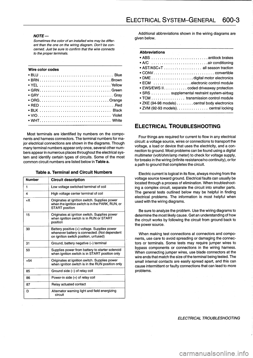
Wire
color
codes
"
BLU
.........
.
..
..
...
.
.................
Blue
"
BRN
....:....
.
..
..
...
..
...............
Brown
"
YEL
.........
.
..
..
...................
.Yellow
"
GRN
.........
.
..
..
...
.
................
creen
"
G
RY
.......
.
.
.
..
..
.....................
G
ray
"
ORG
.........
.
..
..
...
.
..............
.Orange
"
RED
......
...
.
.
..
.....................
.Red
"
BLK
.........
.
..
..
...
.
................
Black
"
VIO
..........
.
..
...
..
..
.......
.
.......
Violet
"
WHT
.........
.
.
....
.
...
:..............
White
Table
a
.
Terminal
and
Circuit
Numbers
Number
1
Circuít
description
1
j
Low
voltage
switched
terminal
of
coi¡
4
1
High
voltage
center
termina¡
of
coi¡
+x
Originates
atignition
switch
.
Supplies
powerwhen
the
ignition
switch
is
in
the
PARK,
RUN,
or
START
position
15
Originates
atignition
switch
.
Supplies
powerwhen
ignition
switch
is
in
RUN
or
START
position
30
Battery
positive
(+)
voltage
.
Supplies
power
whenever
battery
is
connected
.
(Not
dependent
on
ignition
switch
position,
unfused)
31
1
Ground,
battery
negative
(-)
terminal
50
Supplies
power
from
battery
to
starter
solenoid
when
ignition
switch
isin
START
position
only
+54
Originates
atignition
switch
.
Supplies
power
when
ignition
switch
isin
the
RUN
position
only
85
1
Ground
side
(-)
ofrelay
coil
86
1
Power-in
side
(+)
ofrelay
coil
87
1
Relay
actuatedcontact
D
Alternator
warning
light
and
field
energizing
circuit
ELECTRICAL
SYSTEM-GENERAL
600-
3
Additional
abbreviations
shown
in
the
wiring
diagrams
are
given
below
.
Abbreviations
"
ABS
........
.
...
.
...
.
..........
antilock
brakes
"
A/C
........
.
...
..
..
.
.........
.airconditioning
"
AST/ASC+T
.......
...
.
.
.......
al¡
season
traction
"
CONV
.......
.
.
...
.................
convertible
"
DME
........
.
.
...
.......
digital
motor
electronics
"
ECM
.......
.
...
..
..
.
..
electronic
control
module
"
EWS/EWS
II
......
...
.
.
coded
driveaway
protection
"
SRS
........
.
supplemental
restraint
system-airbag
"
TCM
........
.
..
....
.
transmission
control
module
"
ZKE
(94-98
models)
..
..
.
...
central
body
electronics
"
ZVM
(92-93
models)
...
.
.
..
.
.......
central
locking
ELECTRICAL
TROUBLESHOOTING
Most
terminals
are
identified
by
numbers
on
the
compo-
nents
and
harness
connectors
.
The
terminal
numbers
for
ma-
Four
things
are
required
for
current
toflow
in
any
electrical
jor
electrical
connections
are
shown
in
the
diagrams
.
Though
circuit
:
a
voltagesource,
wires
or
connections
to
transport
the
many
terminal
numbers
appear
only
once,
severa¡other
num-
voltage,
a
load
or
device
that
uses
the
electricity,
and
a
con-
bers
appear
in
numerous
places
throughout
the
electrical
sys-
nection
to
ground
.
Most
problemscanbefound
using
a
digital
tem
and
identify
certain
types
ofcircuits
.
Some
of
the
most
multimeter
(volt/ohm/amp
meter)to
check
for
voltage
supply,
common
circuit
numbers
are
listed
below
in
Table
a
.
for
breaks
in
the
wiring
(infinite
resistance/no
continuity),
orfor
a
path
to
ground
that
completesthe
circuit
.
Electric
current
is
logical
in
its
flow,
always
moving
from
the
voltage
sourcetoward
ground
.
Electricalfaults
can
usually
be
located
through
a
process
of
elimination
.
When
troubleshoot-
ing
a
complex
circuit,
separate
the
circuit
into
smaller
parts
.
The
general
testsoutlined
below
may
be
helpful
in
finding
electrical
problems
.
The
information
is
most
helpful
when
used
with
the
wiring
diagrams
.
Be
sure
to
analyze
the
problem
.
Use
the
wiring
diagrams
to
determine
the
most
likely
cause
.
Getan
understanding
of
how
the
circuit
works
by
following
the
circuit
from
groundback
to
the
power
source
.
When
making
test
connections
at
connectors
andcompo-
nents,
use
care
to
avoidspreading
or
damaging
the
connec-
tors
or
terminals
.
Some
tests
may
require
jumper
wires
to
bypass
components
or
connections
in
the
wiring
harness
.
When
connecting
jumper
wires,
use
bladeconnectors
at
the
wire
ends
that
match
the
size
of
the
terminal
being
tested
.
The
small
interna¡
contacts
are
easily
spread
apart,
and
this
can
cause
intermittent
or
faultyconnections
that
can
leadto
more
problems
.
ELECTRICAL
TROUBLESHOOTING
Page 385 of 759
Continuity,
checking
Short
Circuits
from
Battery
CAUTION-
Use
only
a
high
quality
digital
ohmmeter
having
high
input
impedance
when
checking
electronic
componente
.
The
internal
power
source
used
in
most
analog
(swing-need1e)
meterscan
damage
solidstate
components
.
0013239
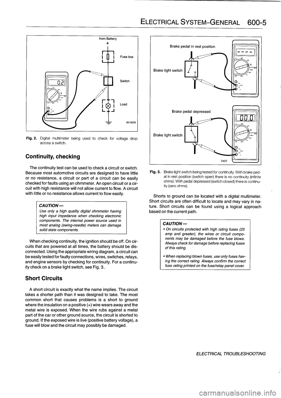
Fig
.
2
.
Digital
multimeter
being
used
to
check
for
voltage
drop
across
a
switch
.
The
continuity
test
can
beused
to
check
a
circuit
or
switch
.
Because
most
automotive
circuits
are
designed
to
have
little
or
no
resistance,
a
circuit
or
part
of
a
circuit
canbe
easily
checked
for
faults
using
an
ohmmeter
.
An
open
circuit
or
a
cir-
cuit
withhigh
resistance
will
not
allow
current
to
flow
.
A
círcuit
with
little
or
no
resistanceallows
current
to
flow
easily
.
When
checking
continuity,
the
ignition
should
be
off
.
On
cir-
cuits
that
are
powered
at
all
times,
the
battery
should
be
dis-
connected
.
Using
the
appropriate
wiring
diagram,
a
circuit
can
be
easily
tested
for
faulty
connections,
wires,
switches,
relays,
and
engine
sensorsby
checking
forcontinuity
.
For
a
continu-
ity
check
on
a
brake
light
switch,
see
Fig
.
3
..
A
short
circuit
is
exactly
what
the
narre
implies
.
The
circuit
takes
a
shorter
paththan
it
was
designed
to
take
.
The
most
common
short
that
causes
problems
is
a
short
to
ground
where
the
insulation
on
a
positive
(+)
wire
wears
away
and
the
metal
wire
is
exposed
.
When
the
wire
rubs
against
a
metal
partof
thecar
or
other
ground
source,
the
circuit
is
shorted
to
ground
.
If
the
exposed
wire
is
live
(positive
battery
voltage),
a
Puse
will
blow
and
the
circuit
may
possibly
be
damaged
.
ELECTRICAL
SYSTEM
-
GENERAL
600-
5
Brake
light
switch
Brake
pedal
in
rest
position
Q
Brake
pedal
depressed
Brake
light
switch
Fig
.
3
.
Brake
light
switchbeing
tested
for
continuity
.
With
brake
ped-
alin
rest
position
(switch
open)
there
is
no
continuity
(infinite
ohms)
.
With
pedal
depressed
(switch
closed)
there
is
continu-
ity
(zero
ohms)
.
Shorts
to
groundcanbe
located
with
a
digital
multimeter
.
Short
circuits
are
often
difficult
to
locate
and
may
vary
in
na-
ture
.
Short
circuits
can
befound
using
a
logical
approach
based
onthe
current
path
.
CAUTION
-
"
On
circuits
protected
with
high
rating
fuses
(25
amp
and
greater),
the
wires
or
circuit
compo-
nents
may
be
damaged
before
the
fuse
blows
.
Always
check
for
damage
before
replacing
fuses
of
this
rating
.
"
When
replacing
blown
fuses,
use
only
fuses
hav-
ingthe
correct
rating
.
Always
confirm
the
correct
fuse
rating
printed
on
the
fuselrelay
panelcover
DC
ELECTRICAL
TROUBLESHOOTING
Page 387 of 759
610
Electrical
Component
Locations
GENERAL
...........
.
.
.
.
.
.
.
.
.
........
610-1
FOSE
POSITION
TABLES
..
.
.
.
.
.
.....
.
610-19
FUSE
AND
RELAY
POSITIONS
.
...
.
.
.
.
.
610-1
Fuse
Positions
.
.
.
................
.
.
.
.
.
610-1
Relay
Positions
.
.
.
.....
.
.
.
........
.
.
.
.
.
610-2
Auxiliary
RelayPanel
.....
.
...
.
........
.
610-2
SplicePanel,
Left
.
.
.
...
.
.
.
...
.
........
.
610-2
SplicePanel,
Right
.
.
.
.
.
.
.
.
...
.
.........
610-3
COMPONENT
LOCATIONS
.
.
.
.
.......
.
.610-3
Component
Location
Table
.
.
.
.
.
.
.........
610-9
GENERAL
FUSE
AND
RELAY
POSITIONS
This
repair
group
covers
f
use,
relay,
and
control
module
lo-
The
front
power
distribution
box,
an
auxiliary
relay
panel,cation
information
.
Electrical
equipment
and
accessories
in-
and
two
auxiliary
splice
panels
contain
most
of
the
fuses
and
stalled
varies
depending
on
model
and
model
year
.
Always
relays
in
E36
vehicles
.
Refer
to
the
component
location
later
confirm
that
the
proper
electrical
component
has
been
identi-
in
this
section,
as
well
as
the
tables
at
the
end
of
this
repair
fied
by
using
the
electrical
wiring
diagrams
.
group
for
electrical
component
location
.
WARNING
-
On
cars
equipped
with
airbags,
special
precautionsapply
to
any
electrical
system
testing
orrepair
.
Air-
bag
units
areexplosive
devices
and
mustbe
han-
dled
with
extremecare
.
Before
starting
any
work
onan
airbag
equipped
car,
refer
to
the
wamings
and
cautions
in
721
Airbag
System
(SRS)
.
CAUTION
-
"
Prior
to
disconnectiog
the
battery,
read
the
bat-
tery
disconnection
cautions
given
at
the
front
of
this
manual
on
page
viii
.
"
Relay
and
fuse
positions
are
subject
to
changeand
may
varyfrom
car
to
car
.
If
questions
arise,
an
authorized
BMW
dealer
is
the
best
source
for
the
most
accurate
and
up-to-date
information
.
"
A
good
way
to
verify
a
relay
position
isto
com-
pare
the
wiring
colors
at
the
relay
socket
to
thecolors
indicated
on
the
wiring
diagrams
located
at
the
rear
of
this
manual
.
"
Always
switchthe
ignition
off
and
disconnect
the
negative
(-)
battery
cable
before
removing
any
electrical
components
.
"
Connect
and
disconnect
ignition
system
wires,
multiple
connectors,
and
ignition
test
equipment
leads
only
while
the
ignition
is
switched
off
.
"
Only
usea
digital
multimeter
for
electrical
tests
.
ELECTRICAL
COMPONENT
LOCATIONS
610-1
TABLES
a
.
E36Component
Locations
...........
.
.
..
...
610-10b
.
1992
E36
Fuse
Positions
..........
..
.
.
.....
610-20c
.
1993
E36
Fuse
Positions
..........
..
..
.
....
610-22d
.
1994
E36
Fuse
Positions
.........
...
.......
610-24e
.
1995
E36
Fuse
Positions
.........
...
.......
610-26
f
.
1996
E36
Fuse
Positions
.........
...
.......
610-28g
.
1997-1998
E36
Fuse
Positions
..
.
..
...
.......
610-30
Fuse
Positions
CAUTION
-
"
Replace
fuses
with
those
of
the
same
rating
.
In-
stalling
a
fuse
with
higher
rating
can
lead
to
cir-
cuit
failure
and
may
also
start
a
fire
.
"
Relay/fuse
positions
vary
by
model
and
equip-
ment
.
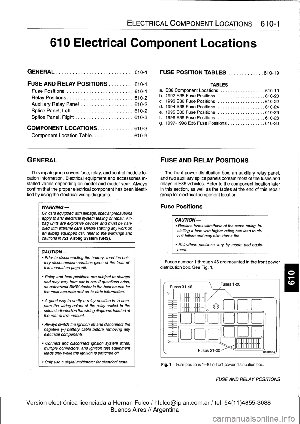
Fuses
number
1
through
46
are
mounted
in
the
front
power
distribution
box
.
See
Fig
.
1.
Fuses
31-46
~
Illlllllllll
°
-
Ilmmlmomlmoi
Fuses
1-20
(a
1
:1
E
El
~
~O!7
L~~n
4~
i
Fuses
21-30
Fig
.1.
Fuse
positions
1-46
in
front
power
distribution
box
.
0013034
FUSE
AND
RELAY
POSITIONS
Page 419 of 759
611
Wipers
and
Washers
GENERAL
..
.
.
.
.
.
.
.
.
.
.
.
.
.
.....
.
......
.
611-1
Windshield
wiper
motor,
removing
and
installing
.
...............
.611-8
WIPER
BLADES
.
.
.
.....
.
.
.
.
.
.
...
....
.611-1
Wiper
Blade
Cleaning
Problems
.
.
.
.
.
.
.....
611-1
Wiper
blades,replacing
...
.
.
.
.
.
.
.
.
.
.....
611-1
Wiper
blade
inserts,
replacing
.
.
.
.
.
.
.
.
.....
611-2
Wiper
arms,
removing
and
installing
.
.
.
.....
611-2
WINDSHIELD
WIPER
ASSEMBLY
.
.
.....
611-3
Windshield
wiper
assembly,
removing
and
installing
(4-door
models)
.
.
.
.
.
.
.....
611-3
Windshield
wiper
assembly,
removing
and
installing
(2-door
models)
.
.
.
.
.
.
.....
611-5
GENERAL
This
repair
group
covers
windshield
wiper
and
washer
sys-
tem
repair
information
.
Please
note
that
some
procedures
are
different
for
2-
and
4-door
models
.
The
windshield
wiper/washer
stalk
switch
assembly
is
cov-
ered
in
612
Switches
and
Electrical
Accessories
.
Electrical
NOTE-
wiring
diagrams
and
relays
for
the
wiper/washer
system
are
BMwhas
available
a
special
toollgauge
(BMWspecial
covered
in
Electrical
Wiring
Diagrams
.
tool
no
.
00
9210)
to
align
the
angle
of
the
wiper
arm
to
the
windshield
glass
.
WIPERBLADES
CA
UTION-
Never
turn
on
the
wiper
blades
while
the
hood
is
open
.
Damage
to
the
wiper
system
and
hood
may
occur
.
Toensure
safetyduring
wiper
biade
system
procedures,
remove
the
windshieldwiper
fuse
.
See
610
Electrical
Component
Locations
.
Wiper
Blade
Cleaning
Problems
Common
cleaning
problems
with
thewipers
includestreak-
ing
or
sheeting,
waterdrops
after
wiping,
and
blade
chatter
.
Streaking
is
usually
caused
when
wiper
blades
are
coated
with
road
film
or
car
wash
wax
.
Clean
the
blades
using
soapy
water
.
If
cleaning
does
not
cure
the
problem,
the
blades
should
be
replaced
.
BMW
recommends
replacing
the
wiper
blades
twice
a
year,
before
and
after
the
cold
season
.
WIPERS
AND
WASHERS
611-1
WINDSHIELD
CLEANING
SYSTEM
......
611-9
Windshield
spray
nozzle,
removing
and
installing
.......
.
........
.611-9
Washer
fluid
reservoir,
replacing
.........
.611-9
Windshield
washer
fluid
pump,
replacing
..
.
......
.
........
.611-9
Washer
fluid
level
sensor,
replacing
(models
with
check
control)
.
.
.
.
........
611-10
Wiper
blade
chatter
may
be
caused
by
dirty
or
worn
blades,
or
by
wiper
arms
that
areout
of
alignment
.
Clean
the
blades
and
windshield
as
described
above
.
Adjust
the
wiper
arm
so
that
there
is
even
pressure
along
the
blade,
and
so
that
the
blade
at
rest
is
perpendicular
to
the
windshield
.
If
problems
persist,
theblades
and
wiper
arms
should
be
replaced
.
The
wiper
blades
can
be
renewed
in
one
of
two
ways
:
either
by
replacing
the
complete
blade
or
by
replacing
just
therubber
insert
.
Insert
replacement
is
the
mosteconomicalmethod,
al-
though
overtime
the
wiperblade
itselfwill
become
worn
.
One
ruleof
thumb
wouldbe
to
replace
just
the
inserts
every
second
time
.
Wiper
blades,
replacing
1
.
Pivot
wiper
arm
off
windshield
.
2
.
Position
wiperblade
approximately
perpendicular
to
wiper
arm
.
3
.
Remove
wiperblade
from
wiper
arm
by
depressing
re-
taining
tab
and
sliding
blade
out
of
arm
.
See
Fig
.
1
.
Drops
that
remain
behind
after
wiping
are
usually
caused
by
NOTE-
oil,
road
film,
or
diesel
exhaust
residue
onthe
glass
.
Use
an
Some
wiperblade
versions
may
havetwo
retaining
alcohol
or
ammonia
solution
or
a
non-abrasive
cleaner
(such
tabs
.
a
s
Bon-Ami
to
clean
the
windshield
.
GENERAL
Page 422 of 759
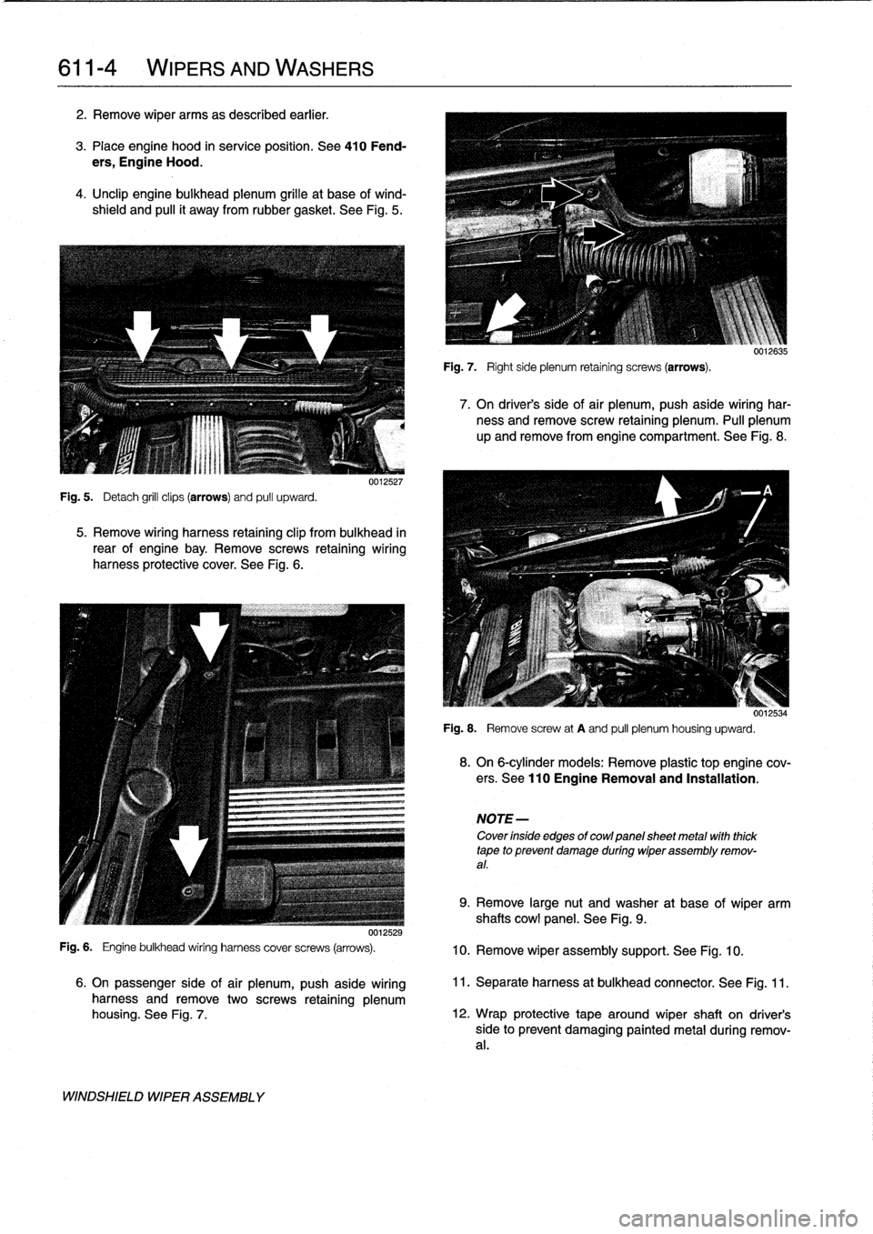
611-
4
WIPERS
AND
WASHERS
2
.
Remove
wiper
arms
as
described
earlier
.
3
.
Place
engine
hood
in
service
position
.
See
410
Fend-
ers,
Engine
Hood
.
4
.
Unclip
engine
bulkhead
plenum
grille
at
base
of
wind-
shield
and
pulí
it
away
from
rubbergasket
.
See
Fig
.
5
.
Fig
.
5
.
Detach
grill
clips
(arrows)
and
pull
upward
.
0012527
5
.
Remove
wiring
harness
retaining
clip
frombulkhead
in
rear
of
engine
bay
.
Remove
screws
retaining
wiring
harness
protective
cover
.
See
Fig
.
6
.
0012529
Fig
.
6
.
Engine
bulkhead
wiring
harness
cover
screws
(arrows)
.
WINDSHIELD
WIPER
ASSEMBLY
Fig
.
7
.
Right
side
plenum
retaining
screws
(arrows)
.
7
.
On
driver's
side
of
air
plenum,
push
aside
wiring
har-
ness
and
remove
screw
retaining
plenum
.
Pull
plenum
up
andremove
from
engine
compartment
.
See
Fig
.
8
.
001¿534
Fig
.
8
.
Remove
screw
at
A
and
pull
plenum
housing
upward
.
8
.
On
6-cylinder
models
:
Remove
plastic
top
engine
cov-
ers
.
See
110Engine
Removal
and
Installation
.
NOTE-
Cover
ínside
edges
of
cowlpanelsheet
metal
with
thick
tape
to
prevent
damage
during
wiper
assembly
remov-
al
.
9
.
Remove
large
nut
and
washer
at
base
of
wiper
arm
shafts
cowi
panel
.
See
Fig
.
9
.
10
.
Remove
wiper
assembly
support
.
See
Fig
.
10
.
6
.
On
passenger
side
of
air
plenum,
push
aside
wiring
11
.
Separateharness
at
bulkhead
connector
.
See
Fig
.
11
.
harness
and
remove
twoscrews
retaining
plenum
housing
.
See
Fig
.
7
.
12
.
Wrap
protective
tape
around
wiper
shaft
on
driver's
side
to
prevent
damaging
painted
metal
during
remov-
al
.
Page 423 of 759
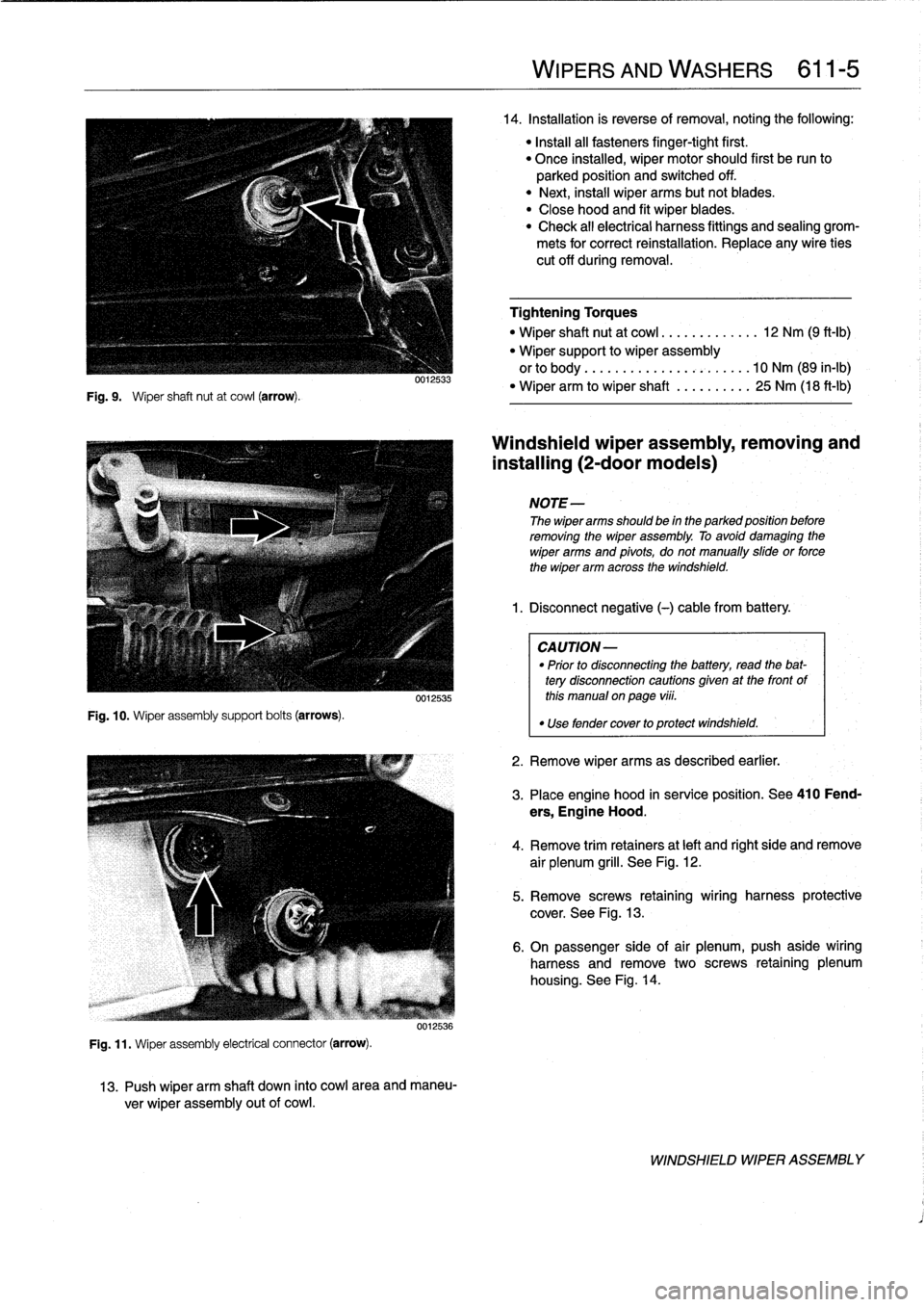
Fig
.
9
.
Wiper
shaft
nut
at
cowl
(arrow)
.
Fig
.
10
.
Wiper
assembly
support
bolts
(arrows)
.
0012533
0012535
Fig
.
11
.
Wiper
assembly
electrical
connector
(arrow)
.
0012536
13
.
Push
wiper
arm
shaft
down
into
cowl
area
and
maneu-
ver
wiper
assembly
out
of
cowl
.
WIPERS
AND
WASHERS
611-
5
14
.
Installation
is
reverse
of
removal,noting
the
following
:
"
Install
all
fasteners
finger-tight
first
.
"
Once
installed,
wiper
motor
should
first
be
run
to
parked
position
and
switched
off
.
"
Next,
instaf
wiper
arms
butnotblades
.
"
Close
hood
and
fit
wiper
blades
.
"
Check
all
electrical
harness
fittings
and
sealing
grom-
mets
for
correct
reinstallation
.
Replace
any
wire
ties
cut
off
during
removal
.
Tightening
Torques
"
Wiper
shaft
nut
at
cowl
.............
12
Nm
(9
ft-Ib)
"
Wiper
support
to
wiper
assembly
orto
body
..
..
..
.
...............
10
Nm
(89
in-lb)
"
Wiper
arm
to
wiper
shaft
..........
25
Nm
(18
ft-lb)
Windshieldwiper
assembly,
removing
and
installing
(2-door
modeis)
NOTE-
The
wiper
arms
should
be
in
the
parked
position
before
removing
the
wiper
assembly
.
To
avoid
damaging
the
wiper
arms
and
pivots,
donotmanually
sidde
or
force
the
wiper
arm
across
the
windshield
.
1
.
Disconnect
negative
(-)cablefrom
battery
.
CAUTION-
"
Prior
to
disconnectiog
the
battery,
read
the
bat-
tery
disconnection
cautionsgiven
at
the
front
of
this
manual
on
page
viii
.
"
Use
fendercover
to
protect
windshield
.
2
.
Remove
wiper
arms
as
described
earlier
.
3
.
Place
engine
hood
in
service
position
.
See410
Fend-
ers,
Engine
Hood
.
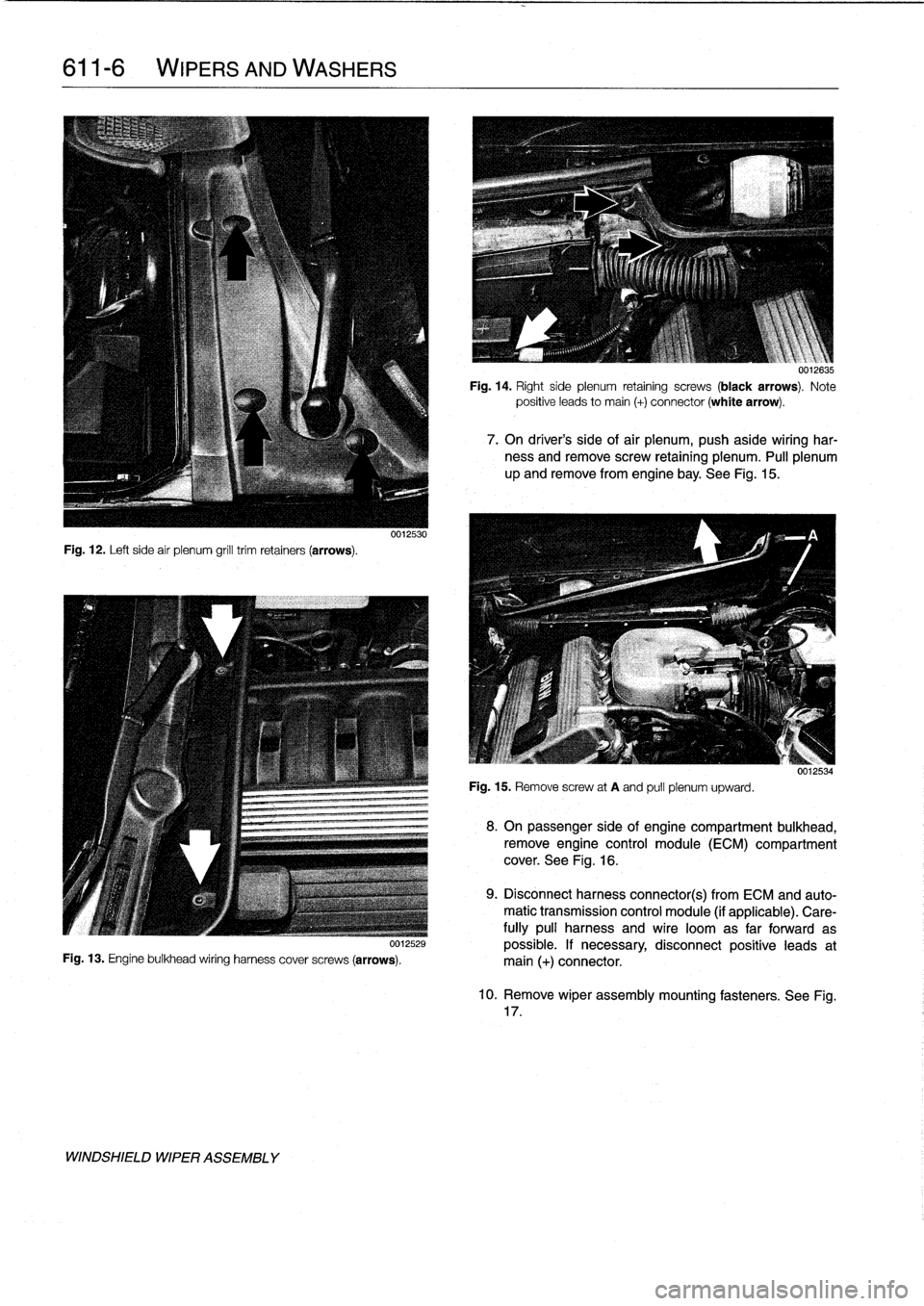
4
.
Remove
trim
retainers
at
left
and
right
side
and
remove
air
plenum
grill
.
See
Fig
.
12
.
5
.
Remove
screws
retaining
wiring
harness
protective
cover
.
See
Fig
.
13
.
6
.
On
passenger
side
of
air
plenum,push
aside
wiring
harness
and
remove
two
screws
retaining
plenum
housing
.
See
Fig
.
14
.
WINDSHIELD
WIPER
ASSEMBLY
Page 424 of 759
611-
6
WIPERS
AND
WASHERS
Fig
.
12
.
Left
side
air
plenum
grill
trim
retainers
(arrows)
.
uu12529
Fig
.
13
.
Engine
bulkhead
wiring
harness
cover
screws
(arrows)
.
WINDSHIELD
WIPER
ASSEMBLY
Fig
.
15
.
Remove
screw
at
A
and
pull
plenum
upward
.
0012635
Fig
.
14
.
Right
side
plenum
retaining
screws
(black
arrows)
.
Note
positive
leads
to
main
(+)
connector
(white
arrow)
.
7
.
On
driver's
side
of
air
plenum,
push
aside
wiring
har-
ness
and
remove
screw
retaining
pienum
.
Pull
plenum
up
and
remove
from
engine
bay
.
See
Fig
.
15
.
8
.
On
passenger
side
of
engine
compartment
bulkhead,
remove
engine
control
module
(ECM)
compartment
cover
.
See
Fig
.
16
.
9
.
Disconnectharness
connector(s)
from
ECM
and
auto-
matic
transmission
control
module
(if
applicable)
.
Care-
fully
pull
harness
and
wire
loomas
far
forward
as
possible
.
If
necessary,disconnect
positive
leads
at
main
(+)
connector
.
10
.
Remove
wiper
assembly
mounting
fasteners
.
See
Fig
.
17
.
Page 429 of 759
612
Switches
and
Electrical
Accessories
GENERAL
.
.
.
.
.
.
.
.
.
...
.
.
.
.
.
...
.
......
.612-1
Headlight
switch,
replacing
..
.
...
.
.
.
.
.
.
.
.
.
612-5
Foglight
switch,
replacing
....
.
.
.
.
.
.
.
.
.
.
.
.
.
612-5
INTERIOR
SWITCHES
.
.
...
.
.
.
.
.
.
.
.....
612-1
Hazard
warning
switch,
replacing
.
.
.
.
.
.
.
.
.
.612-5
Turn
signal
switch
and
wiper
switch,
Powerwindow
switch,
replacing
.
.
.
...
.
.
.
.
.
612-5
replacing
.
.
.
.
.
.
.
...
.
.
.
.....
.
....
.
.
.
.
612-1
Outside
mirrorswitch,
replacing
.
.
.
.
.....
.
.
.612-6
Ignition
Switch
Assembly
.
.
.
.
.
.
.
.
....
.
...
612-3
Ignition
electrical
switch,
replacing
.
...
.
....
612-3
INTERIOR
LIGHTS
.
.
................
.
..
612-6
Ignition
lock
cylinder,
replacing
.
.
.
.
.....
.
..
612-4
Dome
light,
rear
map
lights,
trunk
light,
Headlight
and
Foglight
Switch
Assembly
.
.
.
.
612-5
replacing
bulbs
.
......
.
.
.
.
.
.
.
.
.
.....
.
.612-7
GENERAL
Turn
signal
switch
and
wiper
switch,
replacing
Thissection
covers
replacement
of
interior
switches
and
accessories
.
The
procedures
for
removing
the
turn
signal
stalk
switch
and
the
wiper
system
stalk
switchare
similar
.
When
working
on
electrical
switches,
always
disconnect
the
negative
(-)
cable
from
the
battery
and
insulate
the
cable
end
to
prevent
accidental
re-connection
.
CAUTION-
Prior
to
disconnectiog
the
battery,
read
the
battery
disconnection
cautions
given
at
the
front
of
this
manual
on
page
viii
.
WARNING
-
The
cars
covered
by
this
manual
are
equipped
with
a
Supplemental
Restraint
System
(SRS)
that
auto-'
matically
deploys
one
or
more
airbags
.
Each
airbag
unit
houses
an
explosive
powerful
charge
.
Any
work
involving
the
SRS
system
should
only
be
per-
formed
byan
authorized
BMW
dealer
.
Making
re-
pairs
without
the
proper
knowledge
and
special
test
equipment
may
cause
serious
personal
injury
.
See
721
Airbag
System
(SRS)
3
.
With
front
wheels
pointed
straight
ahead,
remove
steer-
"
Testing
and
replacement
information
for
the
oil
ores-
¡ng
wheel
.
See
320
Steering
and
Wheel
Alignment
.
sure
switch
is
covered
in
119
Lubrication
System
.
NOTE-
"
Wirfng
diagramscan
be
found
in
Electrical
Wiring
Diagrams
.
"
Fuse,
relay
and
electrical
component
locations
can
be
found
in
610
Electrical
Component
Locations
.
"
Replacement
information
for
thetransmission
gear
position/neutral
safety
switch
is
covered
in
250
Gear-
shift
Unkage
.
INTERIOR
SWITCHES
NOTE
-
To
preventmarring
interior
trim,
wrap
the
tips
of
screw-
drivers
and
pliers
with
tape
beforeprying
out
switches
or
electrical
accessories
.
SWITCHES
AND
ELECTRICAL
ACCESSORIES
612-1
1
.
Disconnect
negative
(-)
cable
from
battery
and
cover
terminal
with
insulating
material
.
2
.
Remove
airbag
unit
from
steering
wheel
.
See
721
Air-
bag
System
(SRS)
.
Store
airbag
unit
in
a
safe
placew¡th
pad
facing
up
.
NOTE
-
To
helo
with
reassembly,
mark
steering
wheel
and
col-
umn
before
disassembly
.
4
.
Remove
trim
panel
from
lower
left
side
of
instrument
panel
.
See513
Interior
Trim
.
INTERIOR
SWITCHES
Page 440 of 759
620-
4
INSTRUMENTS
MULTI-INFORMATION
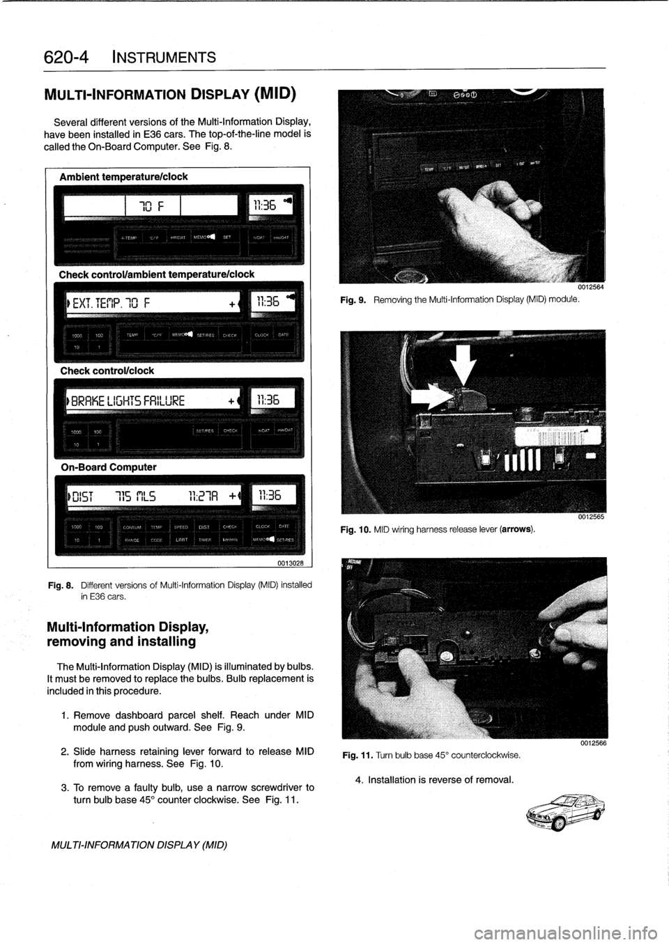
DISPLAY
(MID)
Severa¡
different
versionsof
the
Multi-Information
Display,
have
been
installed
in
E36
cars
.
The
top-of-the-line
model
is
called
the
Oh-BoardComputer
.
See
Fig
.
8
.
Ambient
temperature/ciock
Check
control/clock
0013028
Fig
.
8
.
Different
versions
of
Multi-Information
Display
(MID)
installed
in
E36
cars
.
Multi-Information
Display,
removing
and
installing
The
Multi-Information
Display
(MID)
is
illuminated
by
bulbs
.
It
mustbe
removed
to
replace
the
bulbs
.
Bulb
replacement
is
included
in
this
procedure
.
1
.
Remove
dashboard
parcel
shelf
.
Reach
under
MID
module
and
pushoutward
.
See
Fig
.
9
.
2
.
Slide
harness
retaining
lever
forward
to
release
MID
from
wiring
harness
.
See
Fig
.
10
.
3
.
To
Rmove
a
faulty
bulb,
use
anarrow
screwdriver
to
turn
bulb
base
45°
counter
clockwíse
.
See
Fig
.
11
.
MULTI-INFORMATIONDISPLAY
(MID)
111
Fig
.
9
.
Removing
the
Multi-Information
Display(MID)
module
.
0012564
Fig
.
10
.
MID
wiring
harness
release
lever
(arrows)
.
Fig
.
11
.
Turn
bulb
base
45°
counterclockwise
.
4
.
Installation
is
reverse
of
removal
.
0012566
Page 448 of 759
640-2
HEATING
AND
AIR
CONDITIONING
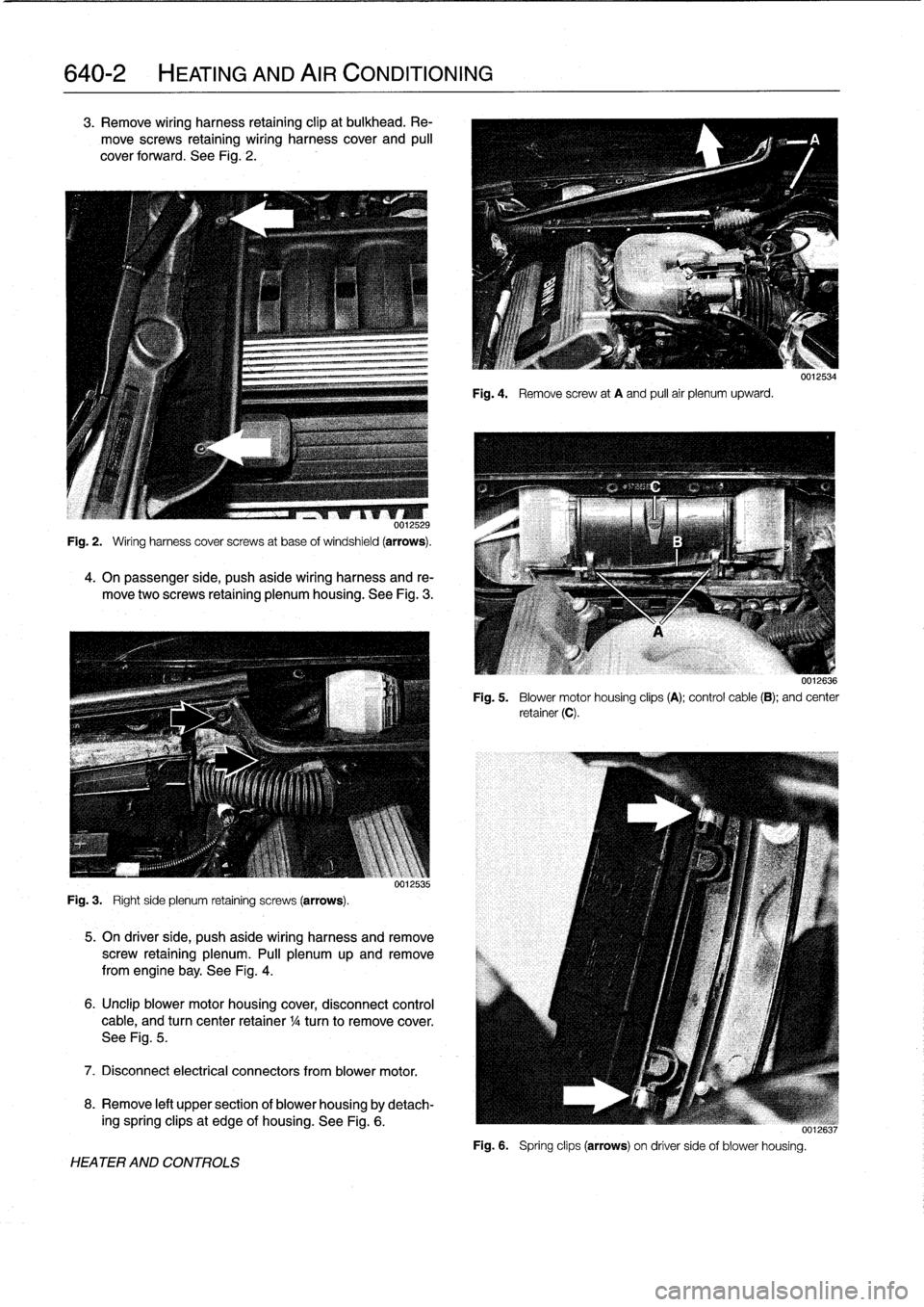
3
.
Remove
wiring
harness
retaining
clip
at
bulkhead
.
Re-
move
screws
retaining
wiring
harness
cover
and
pull
cover
forward
.
See
Fig
.
2
.
0012529
Fig
.
2
.
Ming
harness
cover
screws
at
base
ofwindshield
(arrows)
.
4
.
On
passenger
side,
push
aside
wiring
harness
and
re-
move
two
screws
retaining
plenum
housing
.
See
Fig
.
3
.
Fig
.
3
.
Ríghtside
plenum
retaining
screws
(arrows)
.
VU1L535
5
.
On
driverside,
push
aside
wiring
harness
and
remove
screw
retaining
plenum
.
Pull
plenum
up
and
remove
from
engine
bay
.
See
Fig
.
4
.
6
.
Unclip
blower
motor
housing
cover,
disconnect
control
cable,
and
turn
center
retainer
1
/4
turn
to
remove
cover
.
See
Fig
.
5
.
7
.
Disconnect
electrical
connectors
from
blower
motor
.
8
.
Remove
left
upper
section
of
blower
housingby
detach-
ing
spring
clipsat
edge
of
housing
.
See
Fig
.
6
.
HEATER
AND
CONTROLS
Fig
.
4
.
Remove
screw
at
A
and
pull
air
plenumupward
.
0012534
0012636
Fig
.
5
.
Blower
motor
housing
clips
(A)
;
control
cable
(B)
;
and
center
retainer(C)
.
i
[u6,
Fig
.
6
.
Spring
clips
(arrows)
on
driver
sideof
blower
housing
.