disa BMW 318i 1997 E36 Workshop Manual
[x] Cancel search | Manufacturer: BMW, Model Year: 1997, Model line: 318i, Model: BMW 318i 1997 E36Pages: 759
Page 14 of 759
010-
6
FUNDAMENTALS
FOR
THE
DO-ITYOURSELF
OWNER
In
places
where
a
shaft
mustpass
through
a
housing,
flexible
lip
seals
areused
to
keep
the
lubricating
oil
or
grease
from
leak-
ingout
past
the
rotating
shaft
.
Seals
should
never
be
reused
once
they
have
been
removed
.
When
removing
a
seal,
be
care-
ful
not
lo
scratch
or
otherwise
damage
the
metal
surfaces
.
Even
minor
damage
to
sealing
surfaces
can
cause
sea¡
damage
and
leakage
.
The
key
to
sea¡
installation
is
to
get
the
sea¡
in
straight
without
damaging
¡t
.
Use
a
sea¡
driver
that
is
the
same
diameter
as
the
seal
housing
to
gently
and
evenly
insta¡I
into
place
.
If
a
proper
size
seal
driver
is
not
available,
a
socket
of
the
right
size
will
do
.
When
installing
a
seal,
¡t
a
good
idea
to
coat
the
sea¡
with
o¡I
to
aid
installation
.
Some
seals
are
directional
and
special
instal-
lation
instructions
apply
.
Make
sure
¡t
is
installed
with
the
lip
fac-
ing
the
correct
way
.
Normally
the
lip
faces
the
inside
.
Note
the
installation
direction
of
the
old
sea¡before
removing
¡t
.
Electrical
Testing
Many
electrical
problems
canbe
understood
and
solved
with
only
a
little
fundamental
knowledge
of
how
electrical
circuits
Insulate
the
finished
connection
.
Electronics
stores
can
sup-
function
.
ply
heat-shrinkable
insulating
tubing
that
can
be
placed
onto
the
wire
before
connectiog,
slid
over
the
finished
joint,
and
Electric
current
only
flows
in
a
complete
circuit
.
To
operate,
shrunk
to
a
tight
fit
with
a
heat
gun
orhair
dryer
.
The
nextbest
every
electrical
device
in
thecar
requires
a
complete
circuit
in-
alternative
is
electrical
tape
.
Make
sure
the
wire
is
clean
and
cluding
a
voltage
source
and
a
pathto
ground
.
The
positive
(+)
free
ofsolder
flux
or
other
contamination
.
Wrap
the
joint
tightly
side
of
the
battery
is
the
original
voltagesource,
and
ground
is
to
sea¡
out
moisture
.
See
600
Electrical-General
for
more
in-
any
retum
path
to
the
negative
()
-
side
ofth
e
battery°
whether
li
formation
.
through
the
wiring
harness
or
thecar
body
.
Except
for
portions
of
the
charging
system,
al¡
electrical
current
in
the
car
is
direct
current
(DC)
and
flows
from
positive
(+)
to
negative
(-)
.
BVYING
PART$
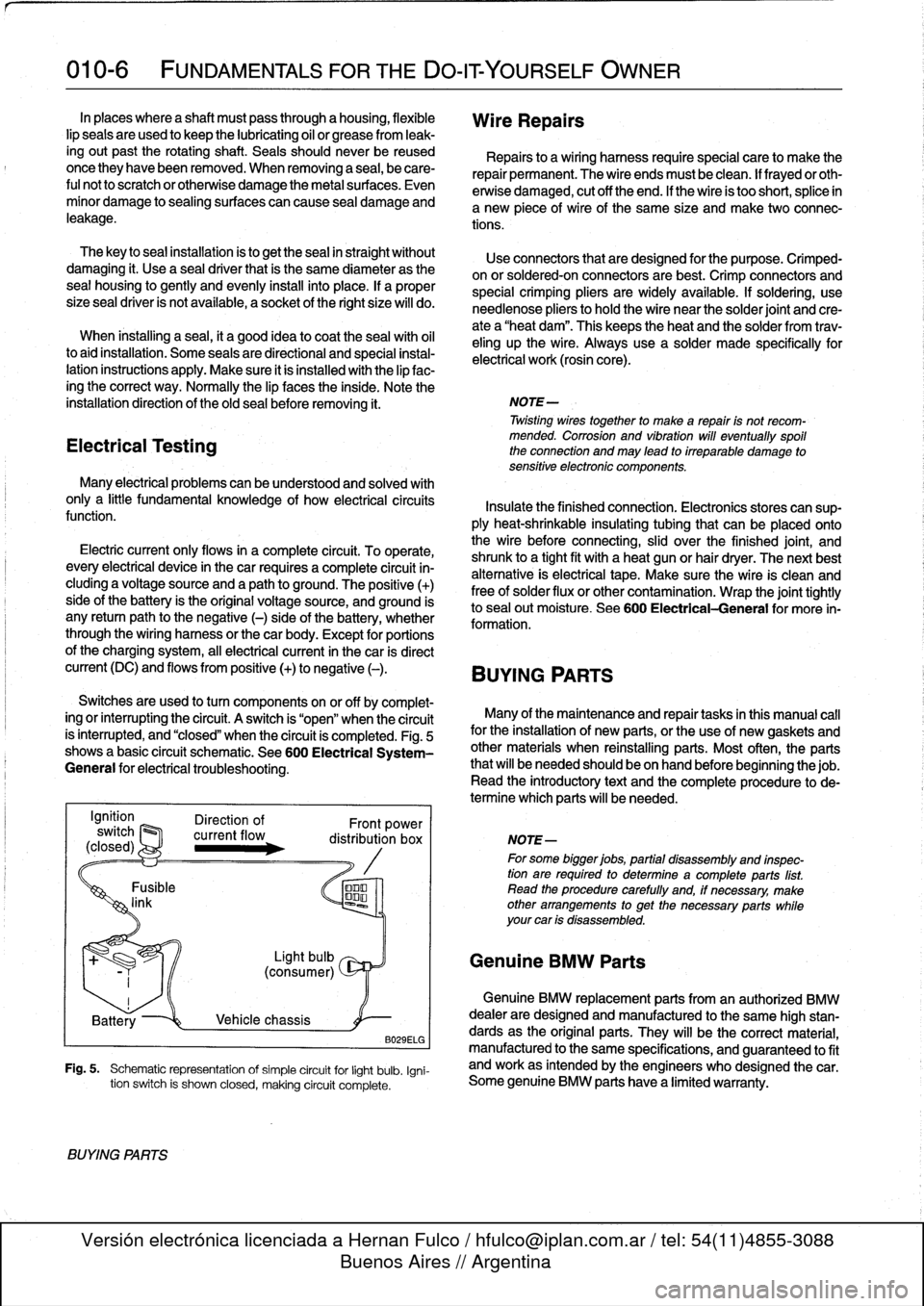
Switches
are
used
to
turn
components
on
or
off
by
complet-
ing
or
interrupting
#he
circuit
.
A
switch
is
"open"
when
the
circuit
Many
of
the
maíntenance
and
repair
tasks
in
this
manual
cal¡
is
ínterrupted,
and
"closed"
when
the
circuit
is
completed
.
Fig
.
5
for
the
installation
of
new
parte,
or
the
use
of
new
gaskets
and
shows
a
basic
circuit
schematic
.
See600
Electrical
System-
other
materials
when
reinstalling
parts
.
Most
often,
the
parts
General
for
electrical
troubleshooting
.
that
will
be
needed
should
be
on
hand
beforebeginningthe
job
.
Read
the
introductory
text
and
the
complete
procedure
to
de-
termine
which
parts
will
be
needed
.
B029ELG
Fig
.
5
.
Schematic
representation
of
simple
circuit
for
light
bulb
.
Igni-
tion
switch
is
shown
closed,
making
circuit
complete
.
BVYING
PARTS
Wire
Repairs
Repairs
to
a
wiring
harness
requirespecial
care
to
make
the
repair
permanent
.
The
wire
endsmust
be
clean
.
lf
frayedor
oth-
erwise
damaged,
cut
off
the
end
.
If
the
wire
is
too
short,
splice
in
a
new
piece
of
wire
of
the
same
size
and
make
two
connec-
tions
.
Use
connectors
that
are
designed
for
the
purpose
.
Crimped-
on
or
soldered-onconnectors
are
best
.
Crimp
connectors
and
special
crimping
pliers
are
widely
available
.
If
soldering,
use
needlenose
pliers
tohold
the
wire
near
the
solder
joint
and
cre-
ate
a
"heat
dam"
.
This
keeps
the
heat
and
the
solder
from
trav-
eling
up
the
wire
.
Always
use
a
solder
made
specifically
for
electrical
work
(rosin
core)
.
NOTE-
Twisting
wirestogether
to
make
a
repair
is
not
recom-
mended
.
Corrosion
and
vibration
will
eventually
spoil
the
connection
and
may
lead
to
irreparable
damage
to
sensitive
electronic
componente
.
NOTE-
For
some
bigger
jobs,
partial
disassembly
and
inspec-
tion
are
required
to
determine
acomplete
parts
list
.
Read
the
procedure
carefully
and,
if
necessary,
make
other
arrangements
to
get
the
necessary
parts
while
your
car
is
disassembled
.
Genuine
BMW
Parts
Genuine
BMW
replacement
parts
from
an
authorized
BMW
dealer
are
designed
and
manufactured
lo
the
same
high
stan-
dards
as
the
original
parts
.
They
will
be
the
correct
material,
manufactured
to
the
same
specifications,
and
guaranteed
lo
fit
and
work
as
intended
by
the
engineers
who
designed
thecar
.
Some
genuine
BMW
parts
have
a
limited
warranty
.
Page 20 of 759
010-12
FUNDAMENTALSFOR
THE
DO-IT
YOURSELF
OWNER
Jump
Starting
Car
Cars
with
discharged
or
dead
batteries
can
be
jump-started
using
the
good
battery
from
another
car
.
When
jump-starting
the
engine,
always
note
the
following
warnings
.
WARNING
-
"
Battery
acid
(electrolyte)
can
cause
severe
burns,
and
will
damage
the
car
and
clothing
.
lf
electrolyte
is
spilled,
wash
the
surface
with
large
quantities
of
water
.
lfit
gets
finto
eyes,
flush
them
with
water
for
severa¡
minutes
and
cal¡
a
doctor
.
"
Batteries
produce
explosive
and
noxious
gas-
ses
.
Keep
sparks
and
flames
away
.
Do
not
smoke
near
batteries
.
"
Do
not
jump-start
the
engine
if
you
suspect
that
the
battery
is
frozen
.
Trapped
gas
may
explode
.
Allow
the
battery
to
thaw
first
.
"
Do
not
quick-charge
the
battery
(for
boost
start-
ing)for
longer
than
one
minute,
and
donot
ex-
ceed
15
volts
at
the
battery
with
the
boosting
cables
attached
.
Wait
at
least
one
minutebefore
boosting
the
battery
a
second
time
.
"
Some
electrical
system
'comfort"
features
may
not
function
correctly
once
battery
power
is
restored
.
For
example,
the
front
window
one-touch-up
func-
tion
may
be
disabled
.
Some
electrical
systems
will
need
to
be
reinitialized
Consult
the
appropriate
re-
pairgroup
formore
specific
information
.
1
.
Place
cars
close
together,
but
do
not
allow
them
to'touch
each
other
.
Turn
off
the
engine
of
thecar
with
the
good
battery
.
2
.
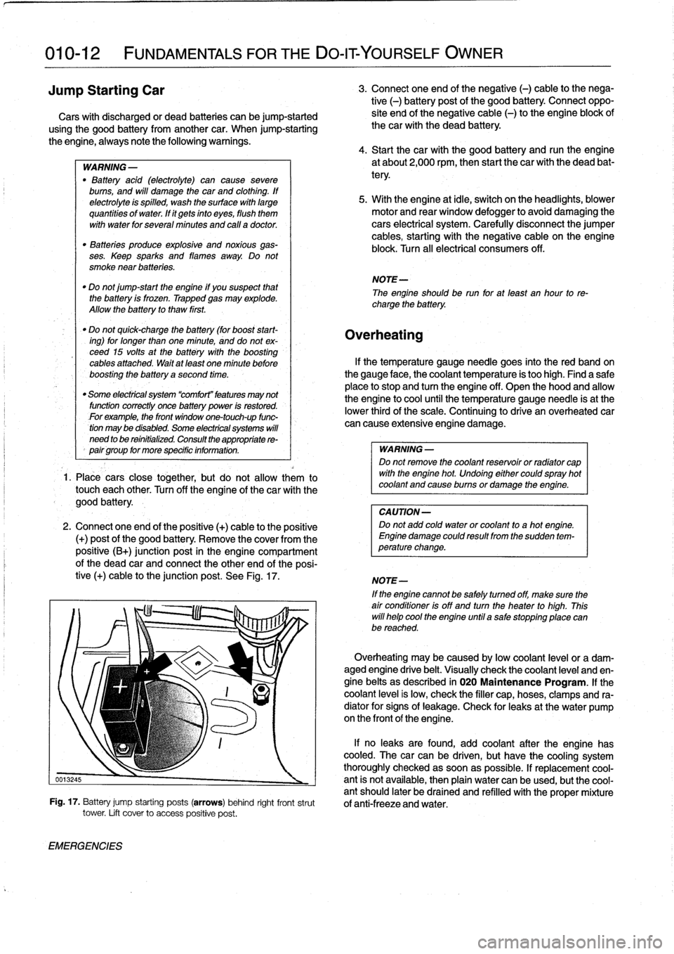
Connect
oneend
of
the
positive
(+)
cable
to
the
positive
(+)
post
of
the
good
battery
.
Remove
the
coverfromthe
positive
(B+)
junction
post
in
the
engine
compartment
of
the
dead
car
and
connect
the
other
end
of
the
posi-
tive
(+)
cable
to
the
junction
post
.
See
Fig
.
17
.
EMERGENCIES
3
.
Connect
one
end
of
the
negative
(-)
cable
to
the
nega-
tive
(-)
battery
post
of
the
good
battery
.
Connect
oppo-
site
end
of
the
negative
cable
(-)
to
the
engine
block
of
thecar
with
the
dead
battery
.
4
.
Start
thecar
with
the
good
battery
and
runthe
engine
at
about2,000
rpm,
then
start
the
car
with
the
dead
bat-
tery
.
5
.
With
the
engine
at
¡dle,
switch
on
the
headlights,
blower
motor
and
rear
window
defogger
to
avoid
damaging
the
cars
electrical
system
.
Carefully
disconnect
the
jumper
cables,
starting
with
the
negative
cable
on
the
engine
block
.
Turn
all
electrical
consumers
off
.
NOTE-
The
engineshould
be
run
for
at
least
an
hour
to
re-
charge
the
battery
.
Overheating
lf
the
temperature
gauge
needle
goes
into
the
red
band
on
the
gauge
face,
the
coolant
temperature
is
too
high
.
Find
a
safe
place
to
stop
and
turn
the
engine
off
.
Open
the
hood
and
allow
the
engine
to
cool
until
the
temperature
gauge
needle
is
at
the
lower
thirdof
the
scale
.
Continuing
to
drive
an
overheated
car
can
cause
extensive
engine
damage
.
WARNING
-
Do
not
remove
the
coolant
reservoir
or
radíator
cap
with
the
engine
hot
.
Undoing
either
couldspray
hot
coolant
and
cause
burns
or
damage
the
engine
.
CAUTION-
Do
not
add
cold
water
or
coolant
to
a
hot
engine
.
Engine
damage
could
result
from
the
sudden
tem-
perature
change
.
NOTE-
If
the
enginecannot
be
safely
tumed
off,
make
sure
the
air
condifioner
isoff
and
turn
the
heater
to
high
.
This
will
helo
cool
the
engine
until
a
salestopping
place
canbe
reached
.
Overheating
may
be
caused
bylow
coolant
leve¡
or
a
dam-aged
engine
drive
belt
.
Visually
check
the
coolant
leve¡
and
en-
gine
belts
as
described
in
020
Maintenance
Program
.
lf
the
coolant
leve¡
is
low,
check
the
filler
cap,hoses,
clamps
and
ra-
diator
for
signs
of
leakage
.
Check
for
leaks
at
the
water
pump
on
the
frontof
theengine
.
lf
no
leaks
are
found,
add
coolant
after
the
engine
has
cooled
.
The
carcan
be
driven,
but
have
the
cooling
system
thoroughly
checked
assoonas
possible
.
lf
replacement
cool
0013245
-
ant
is
not
available,
then
plain
water
canbe
used,
butthe
cool-
antshould
later
be
drained
and
refilled
with
theproper
mixture
Fig
.
17
.
Battery
jump
starting
posts
(arrows)
behind
right
frontstrut
of
anti-freeze
and
water
.
tower
.
Lift
cover
to
access
positive
post
.
Page 22 of 759
010-14
FUNDAMENTALS
FOR
THE
DO-ITYOURSELF
OWNER
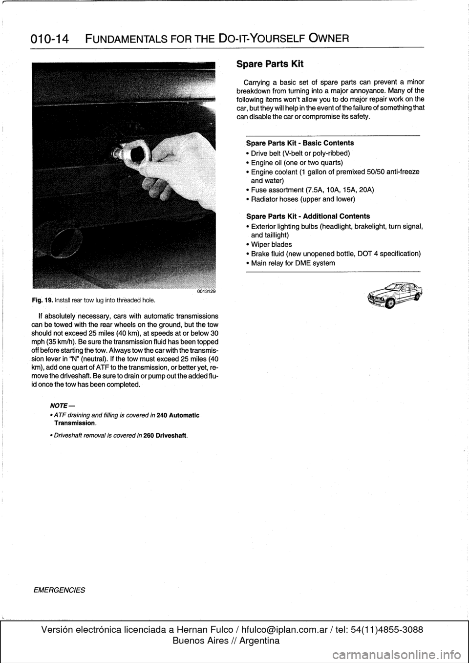
Fig
.
19
.
Instaf
rear
tow
lug
into
threaded
hole
.
if
absolutely
necessary,
cars
with
automatic
transmissions
can
be
towed
with
the
rear
wheels
on
the
ground,
butthe
tow
should
not
exceed
25
miles
(40
km),at
speeds
at
or
below30
mph
(35
km/h)
.
Be
sure
the
transmission
fluid
hasbeen
topped
off
before
starting
the
tow
.
Always
tow
thecar
with
the
transmis-
sion
lever
in
"N"
(neutral)
.
If
the
tow
must
exceed25
miles
(40
km),
add
one
quart
of
ATF
to
the
transmission,
or
better
yet,
re-
move
the
driveshaft
.
Be
sure
to
drain
or
pump
outthe
added
flu-
id
once
the
tow
has
been
completed
.
NOTE-
"
ATF
draining
and
filling
is
covered
in
240
Automatic
Transmission
.
"
Driveshaft
removal
is
covered
in
260
Driveshaft
.
EMERGENCIES
úo1W¿b
Spare
Parts
Kit
Carrying
a
basic
set
of
spare
parts
can
prevent
a
minor
breakdown
from
turning
into
a
major
annoyance
.
Many
of
the
following
itemswon't
allow
you
todo
major
repair
workon
the
car,
but
they
will
help
in
the
event
of
the
failure
of
something
that
can
disable
thecar
or
compromise
its
safety
.
Spare
Parts
Kit
-
Basic
Contents
"
Drive
belt
(V-belt
or
poly-ribbed)
"
Engine
oil
(one
or
two
quarts)
"
Engine
coolant
(1
gallonof
premixed
50/50
anti-freeze
and
water)
"
Fuse
assortment
(7
.5A,
10A,
15A,
20A)
"
Radiator
hoses
(upper
and
lower)
Spare
Parts
Kit
-
Additional
Contents
"
Exterior
lighting
bulbs
(headlight,
brakelight,
turn
signal,
and
taillight)
"
Wiper
biades
"
Brake
fluid
(new
unopened
bottle,
DOT
4
specification)
"
Main
relay
for
DME
system
Page 43 of 759
GENERAL
.
.....
.
.
.
.
.
.
.
...
.
.
.
.
.
.
.
.
.
...
100-1
Cylinder
Block
and
Crankshaft
.
.
.
.
.
.
.
.
.
...
100-1
Connecting
Rods
and
Pistons
.
.
.
.
.
.
.
.
.
.
.
.
.
100-1
Cylinder
Head
and
Valvetrain
.
.
.
.
.
.
.
.
.
.
.
.
.
100-2
VANOS
(Variable
Valve
Timing)
.
.
.
.
.
.
.
.
...
100-2
DISA
(Dual
Resonance
Intake
System)
.
.
.
.
.
100-3
Engine
Management
System
.
.
.
.
.
.
.
.
.
.
.
.
.
100-3
Ignition
......
.
.
.
.........
.
.
.
.
.
.
.
.
.
.
.
.
100-5
Fuel
Delivery
..
.
.
.
.....
.
...
.
.
.
.
.
.
.
.
.
.
.
.
100-5
Cooling
System
.
...........
.
.
.
.
.
.....
.
.
100-5
Lubrication
System
.........
.
.
.
.
.
.
.
.
.
.
.
.
100-5
MECHANICALTROUBLESHOOTING
.
.
.
.
100-5
Warnings
and
Cautions
..
.
...
.
.
.
.
.
.
.
.
.
.
.
.
100-5
Cylinder
compression,
checking
.
.
.
.
.
.
.
.
.
.
.
100-6
EngineMechanical
Troubleshooting
Table
.
.
.
100-7
DRIVEABILITY
TROUBLESHOOTING
...
100-8
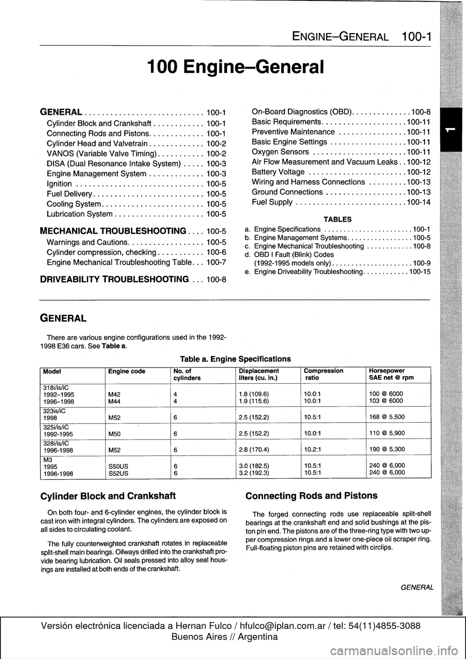
GENERAL
There
are
various
engíne
configurations
used
in
the
1992-
1998
E36
cars
.
See
Table
a
.
On
both
four-
and
6-cylinder
engines,
the
cylinder
block
is
cast
¡ron
with
integral
cyiinders
.
The
cyiinders
are
exposed
on
all
sides
to
circulating
coolant
.
The
fully
counterweighted
crankshaft
rotates
in
replaceable
split-shell
main
bearings
.
Oiiways
drilled
into
the
crankshaft
pro-
vide
bearing
lubrication
.
O¡I
seals
pressed
into
alloy
sea¡
hous-
ings
are
installedat
both
ends
of
the
crankshaft
.
100
Engine-General
Tablea
.
Engine
Specifications
ENGINE-GENERAL
100-1
On-Board
Diagnostics
(OBD)
...
.
.
.
.
.
.
.
.
.
.
.
100-8
Basic
Requirements
....
.
.
.
...
.
.
.
.
.
....
.100-11
Preventive
Maintenance
......
.
.
.
.
.
.....
100-11
Basic
Engine
Settings
..
.
.....
.
.
.
.
.
.....
100-11
Oxygen
Sensors
.
.
.
...
.
.
.
...
.
.
.
.
.
....
.100-11
Air
Flow
Measurement
and
Vacuum
Leaks
.
.100-12
Battery
Voltage
.
.
...........
.
.
.
.
.
.....
100-12
Wiring
and
Harness
Connections
.
.
.
.
.....
100-13
Ground
Connections
...
.
.....
.
.
.
.
.
.....
100-13
Fue¡
Supply
....
.
...........
.
.
..
.....
.100-14
TABLES
a
.
Engine
Specifications
...
...
...........
.
..
..
.100-1
b
.
Engine
Management
Systems
..
..
...........
..
100-5
c
.
Engine
Mechanical
Troubleshooting
..........
.
.
100-8
d
.
OBD
1
Fault
(Blink)
Codes
(1992-1995
models
only)
.
...
..
..
..........
..
.100-9
e
.
Engine
Driveability
Troubleshooting
...........
.100-15
Model
Engine
code
No
.
of
Dispiacement
Compression
Horsepower
cyiinders
liters
(cu
.
in
.)
ratio
SAE
net
@
rpm
318i/is/¡C
1992-1995
M42
4
1
.8
(109
.6)
10
.0
:1
100
@
6000
1996-1998
M44
4
1
.9
(115
.6)
~
10
.0
:1
103
@
6000
323ís/iC
1998
M52
6
2
.5
(152
.2)
10
.5
:1
168
@
5,500
325i/is/iC
1992-1995
M50
6
2
.5
(152
.2)
10
.0
:1
110
@
5,900
328i/is/iC
1996-1998
M52
6
2
.8
(170
.4)
10
.2
:1
190
@
5,300
M3
1995
S50US
6
3
.0
(182
.5)
10
.5:1
240
@
6,000
1996-1998
S52US
6
3
.2
(192
.3)
10
.5:1
240
@
6,000
Cylinder
Block
and
Crankshaft
Connecting
Rods
and
Pistons
The
forged
connecting
rods
use
replaceable
split-shell
bearings
at
the
crankshaft
endand
solid
bushings
at
the
pis-
ton
pin
end
.
The
pistonsare
of
the
three-ring
typewith
two
up-
per
compression
rings
and
a
lowerone-piece
o¡i
scraper
ring
.
Fui¡-floating
piston
pins
are
retained
with
circlips
.
GENERAL
Page 45 of 759
camshaft
secondary
drive,
causing
thecamshaft
to
"advance"
12
.5°
.
The
helical
gears
are
cut
so
that
forward
motion
of
the
gear
cup
is
transiated
into
rotational
motion
of
the
camshaft
.
See
117
Camshaft
Timing
Chain
for
testing
and
repair
infor-
mation
on
the
VANOS
system
.
DISA
(Dual
Resonance
Intake
System)
DISA,usedon
4-cylinder
engines,
is
a
dual
intake
runner
system
that
effectively
provides
the
advantages
of
both
short
and
long
intake
runners
within
the
same
engine
.
For
best
per-
formance,
long
intake
runners
aremost
beneficial
atlow-
and
mid-engine
speeds
(below
4,200
rpm),
and
short
intake
run-
ners
enhance
torque
at
high
engine
speeds
(above4,200
rpm)
.
NOTE-
The
term
DISA
comes
from
the
German
words
Differ-
enzierte
Sauganlage,
and
can
roughty
be
transiated
as
a
differing
intake
manifold
configuration
.
The
DISA
solenoid
valve
is
controlled
by
the
DME
control
module,
using
engine
speed
as
the
primary
input
.
The
main
components
of
the
system
are
the
modified
twin-section
in-
takemanifoldwith
change-over
valve,
the
twin-barrel
throttle
body,
and
the
electrical/pneumatic
actuating
components
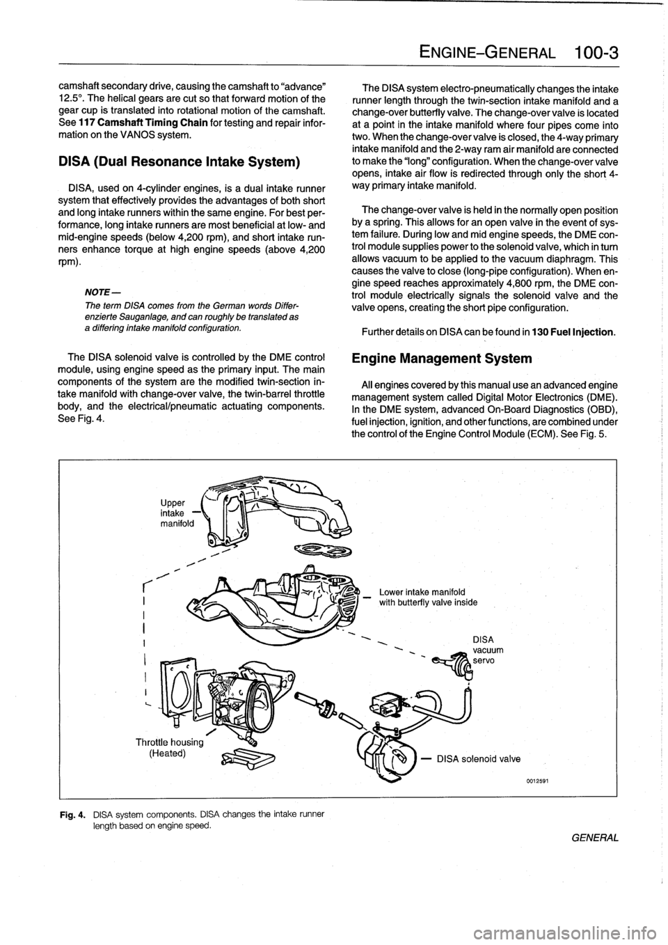
.
See
Fig
.
4
.
r
I
I
I
?
,
in
UpPer,
take
-1
manifold
1
-1
Throttle
housing
(Heated)
q
:lZU
Fig
.
4
.
DISA
system
components
.
DISA
changes
the
intake
runner
length
based
on
engine
speed
.
The
DISA
system
electro-pneumatically
changes
the
intake
runner
length
through
the
twin-section
intake
manifold
and
a
change-over
butterfly
valve
.
The
change-over
valve
is
located
at
a
point
in
the
intake
manifold
where
four
pipes
come
into
two
.
When
the
change-over
valve
is
closed,
the
4-way
primary
intake
manifold
and
the
2-way
ram
air
manifold
areconnected
to
make
the
"long"
configuration
.
When
the
change-overvalve
opens,
intake
air
flow
is
redirected
through
only
the
short
4-
way
primary
intake
manifold
.
The
change-over
valve
is
held
in
the
normally
open
position
bya
spring
.
Thisallows
for
an
open
valve
in
the
event
of
sys-
tem
failure
.
During
low
andmid
enginespeeds,
the
DME
con-
trol
module
supplies
power
to
the
solenoid
valve,
which
in
turn
allows
vacuum
to
be
applied
lo
the
vacuum
diaphragm
.
This
causes
the
valve
to
close
(long-pipe
configuration)
.
When
en-
gine
speed
reaches
approximately
4,800
rpm,
the
DME
con-
trol
module
electrically
signals
the
solenoid
valve
and
the
valve
opens,
creating
the
short
pipe
configuration
:
Further
detafs
on
DISA
canbefound
in
130
Fuel
Injection
.
Engine
Management
System
Al¡
enginescoveredby
this
manual
usean
advanced
engine
management
system
called
Digital
Motor
Electronics
(DME)
.
In
the
DME
system,
advancedOn-Board
Diagnostics
(OBD),
fuel
injection,
ignition,
and
otherfunctions,
are
combined
under
the
control
of
theEngine
Control
Module
(ECM)
.
See
Fig
.
5
.
-
Lower
intake
manifold
DISAvacuum
'
~servo
EíY1z
ENGINE-GENERAL
100-
3
le
-
DISA
solenoid
valve
0012591
/
with
butterfly
va¡
GENERAL
Page 48 of 759
100-6
ENGINE-GENERAL
Cylinder
compression,
checking
A
compression
tester
is
needed
to
make
a
compression
test
.
To
obtain
accurate
test
results,
the
battery
and
starter
must
be
capable
of
cranking
the
engine
at
250-300
rpm,
and
theen-
gine
should
be
at
normal
operating
temperature
.
Use
com-
pressed
air
to
clean
aroundthe
spark
plugs
before
removal
.
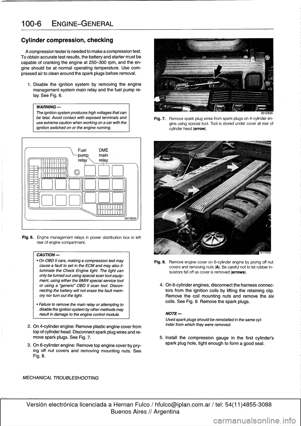
1
.
Disable
the
ignítion
system
by
removing
the
engine
management
system
main
relay
and
the
fuel
pump
re-
¡ay
.
See
Fig
.
6
.
WARNING
-
The
ignítion
system
produces
high
voltages
that
canbe
fatal
.
Avoid
contact
with
exposed
termínals
and
useextreme
caution
when
working
on
acar
wíth
the
ignítion
switched
on
or
the
engine
running
.
Fuel
DM
E
pump
main
re
ay
rel
ay
o
oa
ooa
.,
o00
oao
Fig
.
6
.
Engine
management
relays
in
power
distribution
box
inleft
rear
of
engine
compartment
.
CAUTION-
"
On
OBD
11
cars,
making
a
compression
test
may
causea
faultto
set
in
the
ECM
and
may
also
il-
luminate
the
Check
Engine
light
.
The
light
can
only
be
tumed
out
using
special
scan
tool
equip-
ment,using
eíther
the
BMW
specialservíce
tool
or
using
a
"generic"
OBD
11
scan
tool
.
Discon-
necting
the
battery
will
not
erase
the
fault
mem-
orynor
turn
outthe
light
.
0013034,
0012630
Fig
.
7
.
Remove
spark
plug
wires
from
spark
plugs
on
4-cylinder
en-
gine
using
special
tool
.
Tool
is
stored
under
cover
at
rear
of
cylinder
head
(arrow)
.
Fig
.
8
.
Remove
engine
cover
on
6-cylinder
engine
byprying
off
nut
covers
and
removing
nuts
(A)
.
Be
careful
not
to
let
rubber
in-
sulators
fall
off
as
cover
is
removed
(arrows)
.
4
.
On
6-cylinder
engines,
disconnect
the
harness
connec-
tors
from
the
ignítion
coils
by
lifting
the
retaining
clip
.
Remove
the
coil
mounting
nuts
andremove
the
six
coils
.
See
Fig
.
9
.
Remove
the
sparkplugs
.
"
Failure
to
remove
the
main
relay
or
attempting
to
disable
the
ignítion
system
by
other
methods
may
resultin
damage
to
the
engine
control
module
.
NOTE-
Used
sparkplugs
should
be
reinstalled
in
the
same
cyl-
2
.
On
4-cylinder
engine
:
Remove
plastic
engine
cover
from
inder
fromwhich
they
were
removed
.
top
of
cylinder
head
.
Disconnect
spark
plug
wires
and
re-
move
spark
plugs
.
See
Fig
.
7
.
5
.
Insta¡¡
the
compression
gauge
in
the
first
cylinder's
3
.
On
6-cylinder
engine
:
Remove
top
engine
coverby
pry-
spark
plug
hole,
tight
enough
to
form
a
good
seal
.
ing
off
nut
covers
and
removing
mounting
nuts
.
See
Fig
.
8
.
MECHANICAL
TROUBLESHOOTING
Page 67 of 759
113
Cylinder
Head
Removal
and
Installation
GENERAL
.
...............
.
.
.
.
.
.......
113-1
CYLINDER
HEAD,
6-CYLINDER
.
.
.
.
.
.
.
113-10
Cylinder
head,
removing
(6-cylinder
engine)
..
113-10
CYLINDER
HEAD,
4-CYLINDER
..
.
...
.
.
113-1
Cylinder
head,
installing
(6-cylinder
engine)
...
113-15
Cylinder
head,
removing
(4-cylinder
engine)
...
113-1
E
Cylinder
head,
installing
(4-cylinder
engine)
...
113-6
GENERAL
CYLINDER
HEAD,
4-CYLINDER
The
information
given
inthis
repair
group
assumes
that
the
engine
is
installed
in
the
engine
bay
.
For
cylinder
head,
cam-
Cylinder
head,
removing
shaft,
and
valvetrain
disassembly
and
reconditioning
informa-
(4-cylinder
engine)
tion,
see116
Cylinder
Head
and
Valvetrain
.
For
ease
of
use
this
removal
procedure
is
broken
into
sub-
In
the
procedures
given
below,
engines
are
referred
to
by
sections,
as
follows
:
engine
code
.
If
necessary,
see100
Engine-General
for
en-
gine
code
and
application
information
.
NOTE-
If
a
head
gasket
problem
is
suspected,
acompression
test
will
usually
detectthe
fault
.
See
100
Engine-Gen-
eral
for
compression
testing
information
.
Special
BMW
service
tools
are
required
to
properly
remove
and
install
the
cylinder
head
on
both
the
4-cylinder
and
6-cyl-
inder
engines
.
The
special
tools
are
used
to
time
the
val-
vetrain
to
the
crankshaft
and
to
remove
the
Torx
(El
2)
head
bolts
.
Read
the
procedure
through
before
beginning
thejob
.
Cover
al¡
painted
surfaces
before
beginning
the
removal
procedure
.
As
an
aid
to
installation,
label
all
components,
wires,
and
hoses
before
removing
them
.
Do
not
reuse
gas-
kets,
O-rings
or
seals
during
reassembly
.
WARNING
-
Due
to
risk
of
personal
injury,
be
sure
the
engine
is
cold
before
beginning
the
removalprocedure
.
CYLINDER
HEAD
REMOVAL
AND
INSTALLATION
113-1
General
Coolingsystem,
draining
Cylinder
head
cover,
removing
Intake
manifold,
removing
Timing
chains,
uncoupling
Cylinder
head
assembly,
removing
WARNING
-
Allow
engine
to
cool
before
beginning
this
proce-
dure
.
General
1
.
Disconnect
negative
(-)
cable
from
battery
.
CAUTION
-
"
Prior
to
disconnectiog
the
battery,
read
the
bat-
tery
disconnection
cautions
given
at
the
front
of
this
manual
on
page
viii
.
"
Disconnecting
the
battery
may
erase
fault
codees)
stored
in
control
module
memory
.
Check
for
fault
codes
using
special
BMW
diagnostic
equipment
.
NOTE-
The
battery
is
mounted
in
the
luggage
compartment
behind
the
right
side
trim
panel
.
2
.
Working
underneath
vehicle,
remove
front
exhaust
pipe
from
exhaust
manifold
.
See
Fig
.
1
.
3
.
Disconnect
vacuum
hose
fitting
from
brake
booster
on
rear
bulkhead
.
Plug
opening
in
booster
and
hose
end
.
CYLINDER
HEAD,
4-CYLINDER
Page 74 of 759
113-8
CYLINDER
HEAD
REMOVAL
AND
INSTALLATION
IW?
-
L
'/~f
W
~
4r
"
-
"
;,s
1
12
.
On
M44
engine
:
Place
sensor
wheel
on
intake
cam-
shaft
sprocket
so
that
arrowon
sensor
wheel
points
up
.
13
.
Instan
and
hand-tighten
sprocket
mounting
bolts
.
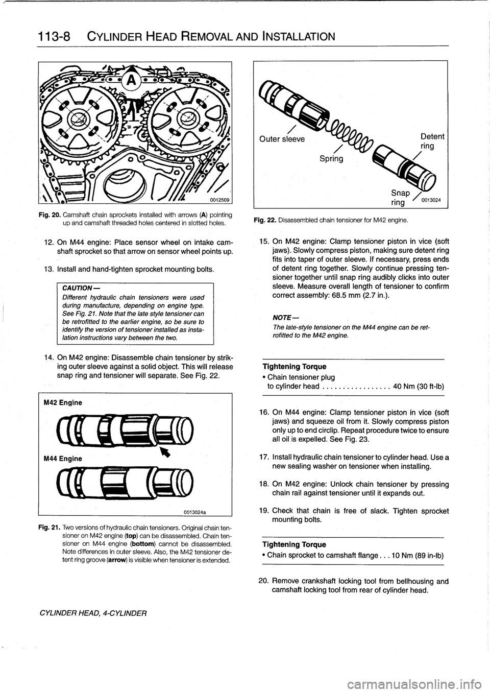
CAUTION-
Different
hydraulic
chaintensioners
were
used
during
manufacture,
depending
onengine
type
.
See
Fig
.
21
.
Note
that
the
late
style
tensioner
can
be
retrofitted
to
the
earlier
engine,
so
be
sure
to
identify
the
version
of
tensioner
installed
as
insta-lation
instructions
vary
between
the
two
.
14
.
On
M42
engine
:
Disassemble
chain
tensioner
by
strik-
ing
outer
sleeve
against
a
solid
object
.
This
will
release
snap
ring
and
tensioner
will
separate
.
See
Fig
.
22
.
M42
Engine
up
and
camshaft
threaded
holes
centered
in
siotted
holes
.
CYLINDER
HEAD,
4-CYLINDER
0013024a
Outer
sl
eve
Detent
ring
Spri
g
Fig
.
22
.
Disassembled
chain
tensioner
for
M42
engine
.
15
.
On
M42
engine
:
Clamp
tensioner
piston
in
vice
(soft
jaws)
.
Slowly
compress
piston,
making
sure
detent
ring
fits
into
taper
of
outer
sleeve
.
If
necessary,
press
ends
of
detent
ring
together
.
Slowly
continuepressing
ten-
sioner
together
until
snap
ring
audibly
clicksinto
outer
sleeve
.
Measure
overall
lengthof
tensioner
to
confirm
correct
assembly
:
68
.5
mm
(2.7
in
.)
.
NOTE-
i
Snap
ring
/0
.13024
The
late-style
tensioner
on
the
M44
engíne
canbe
ret-
rofitted
to
the
M42
engine
.
Tightening
Torque
"Chain
tensioner
plug
to
cylinder
head
.....
.-~
..........
40
Nm
(30
ft-Ib)
16
.
On
M44
engíne
:
Clamp
tensioner
píston
in
vice
(soft
jaws)
and
squeeze
oil
from
it
.
Slowly
compress
piston
only
up
to
end
circlip
.
Repeat
procedure
twice
to
ensure
all
oil
is
expelled
.
See
Fig
.
23
.
17
.
Instan
hydraulic
chain
tensioner
to
cylinder
head
.
Use
a
new
sealing
washer
on
tensioner
when
installing
.
18
.
On
M42
engine
:
Unlock
chain
tensioner
by
pressing
chain
rail
against
tensioner
until
it
expands
out
.
19
.
Check
that
chain
is
free
of
slack
.
Tighten
sprocket
mounting
bolts
.
Fig
.
21
.
Two
versions
of
hydraulic
chain
tensioners
.
Original
chainten-
sioner
on
M42
engine
(top)
can
be
disassembled
.
Chain
ten
sioner
on
M44
engine
(bottom)
cannotbe
disassembled
.
Tightening
Torque
Note
differences
in
outer
sleeve
.
Also,
the
M42
tensioner
de-
"
Chain
sprocket
to
camshaft
flange
.
..
10
Nm
(89
in-lb)
tent
ring
groove
(arrow)
is
visible
when
tensioner
is
extended
.
20
.
Remove
crankshaft
locking
tool
from
bellhousing
and
camshaft
locking
tool
from
rear
of
cylinder
head
.
Page 85 of 759
GENERAL
CYLINDER
HEAD,
DISASSEMBLY
AND
ASSEMBLY
CYLINDER
HEAD
AND
VALVETRAIN
116-1
116
Cylinder
Head
and
Valvetrai
n
GENERAL
.
.....
.
.
.
...
.
.
.
.
.
.
.
.
.
.......
116-1
Hydraulic
cam
followers,
checking
and
replacing
(M42
and
al¡
6-cylinder
engines)
.
...
.....
.
..
116-9
CYLINDER
HEAD,
Valve
guides
.
.
.
...
.
.
.
.
.
.
...
.
.
.
.
.
.
.
.
.
.
116-10
DISASSEMBLY
AND
ASSEMBLY
...
.
...
116-1
Valves
.
.
.
.
.
.
.
.
.
.
.
.
.
...
.
...
.
.
.
.
.
...
.
.
116-11
Camshafts,
removing
and
installing
(M42
engine)
....
.
....
.
.
.
.
.
.
.
.
.
.....
.
.
116-1
Valves,
leak
test
.
.
.
.
.
.
.
.
.
.
...
.
.
.
.
.
.
.
.
.
.
116-11
Camshafts,
removing
and
installing
Valve
stem
oil
seals
.
.
.
.......
.
.
.
.
.
...
.
.
116-11
(M44
engine)
.........
.
.
.
.
.
.
.
.
.
.......
116-3
Valve
seats
.
.
.
.
.
.
.
.
.
...
.
...
.
.
.
.
.
...
.
.116-12
Camshafts,
removing
and
installing
Valve
springs
.
.
.
.
.
.
.
.
...
.
...
.
.
.
.
.
.....
116-12
(6-cylinder
engine)
.....
.
.
.
.
.
.
.
.
.
.......
116-4
Valves,
removing
and
installing
........
.
....
116-6
TABLES
CYLINDER
HEAD
AND
VALVETRAIN,
a
.
Cylinder
Head
Height
........
....
.
..
..........
116-7
RECONDITIONING
.
...
.
.
.
.
.
.
.
.
.
.......
116-7
b
.
Camshaft
Specifications
.......
..
.
..
........
.116-7
Cylinder
head
...
.
.
.
...
.
.
.
.
.
.
.
.
.
....
.
..
116-7
c
.
Valve
Guide
Specifications
....
...
.
..
........
116-10
d
.
Valve
Specifications
...........
..
.
..
........
116-11
Camshaft
.
.
.
.
.
.
.
.
.
.
.
.
.
.
...
.
.
.
.
.
.......
116-7
e
.
Valve
Seat
Dimensions
.........
.
..
..
......
.116-12
Hydraulic
valve
adjusters,
checking
and
replacing
(M44
engine)
..
.
.
.
116-8
Camshafts,
removing
and
installing
(M42
engine)
This
repair
group
covers
cylinder
head
and
valvetrain
ser-
vice
and
repair
.
Most
of
the
repairs
described
here
require
that
The
camshafts
can
be
removed
with
the
cylinder
head
the
cylinder
head
first
be
removed
as
described
in
113
Cylin-
mounted
on
the
engine
.
The
first
step
is
to
remove
the
cylinder
der
HeadRemoval
and
Installation
.
head
cover
.
See
113
Cylinder
HeadRemoval
and
Installa-
tion
.
NOTE-
Special
BMW
service
tools
should
always
be
used
to
remove
"
For
timing
chain
and
VANOS
repair
information,
see
and
install
the
camshafts
.
Removal
and
installation
of
the
cam-
117
Camshaft
Timing
Chain
.
shafts
without
the
special
tools
can
result
in
camshaft
and
valve
"
If
it
is
determined
that
the
cylinder
head
will
require
train
damage
.
significant
reconditioning
work,
a
remanufactured
cyl-
inder
head
may
bea
good
alternative
.
Remanufac-
WARNING-
tured
cylinder
heads
are
available
froman
authorized
The
process
of
evenly
loosening
the
camshaftbear
BMW
dealer
.
ing
cap
nuts
is
NOT
an
acceptable
method
of
re-
moving
the
camshafts
.
Be
sure
to
read
the
The
information
given
in
this
repair
group
is
organized
ac-
procedure
through
before
starting
the¡ob
.
cording
to
engine
code
.
For
engine
applicationinformation,
see100
Engine-General
.
1
.
Disconnect
negative
(-)
battery
cable
.
CAUTION-
Prior
to
disconnectiog
the
battery,
read
the
battery
disconnection
cautions
given
at
the
front
of
this
manualonpage
viii
.
BMW
special
tools
are
required
for
most
cylinder
head
ser-
2
.
Remove
radiator
cooling
fan
shroud
and
cooling
fan
.
vice
described
in
this
repair
group
.
Many
of
these
tools
areex-
See
170
Radiator
and
Cooling
System
.
pensive
and
only
available
through
an
authorized
BMW
dealer
.
If
the
special
tools
are
not
available,
one
altematve
is
to
remove
the
cylinder
head
and
have
it
disassembled
byan
authorized
CAUTION-
BMW
dealer
.
Be
sure
to
read
each
procedure
thoroughlybefore
Radiator
fa
n
has
left
hand
threads
.
starting
a
job
to
determinewhich
special
tools
and
equipment
will
be
necessary
.
CYLINDER
HEAD,
DISASSEMBLYANDASSEMBLY
Page 86 of 759
116-2
CYLINDER
HEADAND
VALVETRAIN
3
.
Remove
timing
chain
sprockets
and
timing
chains
from
7
.
Slowly
release
pressure
oncamshaft
bearing
capsby
camshafts
.
Remove
upper
timing
chain
guidefrom
cyl-
turningeccentric
shaft
.
Remove
bearing
caps
and
inder
head
.
See117
Camshaft
Timing
Chain
.
camshaft
.
Repeat
procedureon
remaining
camshaft
.
NOTE-
It
is
not
necessary
lo
remove
the
lower
timing
chain
cover
.
4
.
Remove
spark
plugs
and
instaf
BMW
special
tool
11
3
260
to
cylinder
head
.
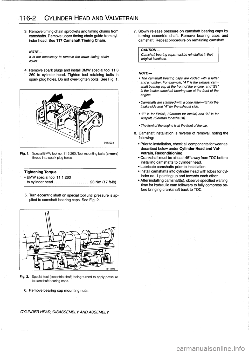
Tighten
tool
retaining
bolts
in
spark
plug
holes
.
Do
not
over-tighten
bolts
.
See
Fig
.
1
.
6
.
Remove
bearing
cap
mounting
nuts
.
0013033
5
.
Turn
eccentric
shaft
on
special
tool
until
pressure
is
ap-
plied
to
camshaft
bearing
caps
.
See
Fig
.
2
.
Fig
.
2
.
Special
tool
(eccentric
shaft)
being
turned
to
apply
pressure
to
camshaft
bearing
caps
.
CYLINDER
HEAD,
DISASSEMBLYAND
ASSEMBLY
CAUTION-
Camshaft
bearing
caps
mustbe
reinstalled
intheir
original
locations
.
NOTE-
"
The
camshaft
bearing
caps
are
coded
wíth
a
letter
anda
number
.
Forexample,
"Al
"ís
the
exhaust
cam-
shaft
bearing
cap
at
the
front
of
the
engíne,
and
"El"
is
the
intake
camshaft
bearing
cap
at
the
front
of
the
engine
.
"
Camshafts
are
stamped
with
a
code
letter-`E"
for
the
intakeside
and
`A"forthe
exhaust
side
.
"
"E"
isforEinlal3,
(German
for
íntake)
and
A"
isfor
Auspuff,
(German
for
exhaust)
.
"
The
front
of
the
engine
is
at
the
front
of
thecar
.
8
.
Camshaft
installation
is
reverse
of
removal,noting
the
following
:
"
Prior
to
installation,
check
al¡
components
for
wear
as
described
below
underCylinder
Head
and
Va¡-
Fig
.1
.
Special
BMW
tool
no
.
11
3
260
.
Tool
mounting
bolts
(arrows)
vetrain,
Reconditioning
.
thread
into
spark
plug
holes
.
"
Crankshaft
must
be
at
least
45°
away
from
TDC
before
installing
camshafts
to
cylinder
head
.
"
Lubricate
camshafts
prior
to
installation
.
Tightening
Torque
"
Install
camshafts
into
cylinder
head
with
lobes
for
cyl-
"
BMW
special
tool
11
1
260
inder
no
.
1
pointing
up
and
towards
each
other
.
to
cylinder
head
.
...
.
.
...........
23
Nm
(17
ft-Ib)
"
After
installing
camshafts),observe
specified
waiting
time
for
hydraulic
cam
followers
to
fully
compress
be-
fore
bringing
crankshaft
back
to
TDC
.