service BMW 318i 1997 E36 Owners Manual
[x] Cancel search | Manufacturer: BMW, Model Year: 1997, Model line: 318i, Model: BMW 318i 1997 E36Pages: 759
Page 274 of 759
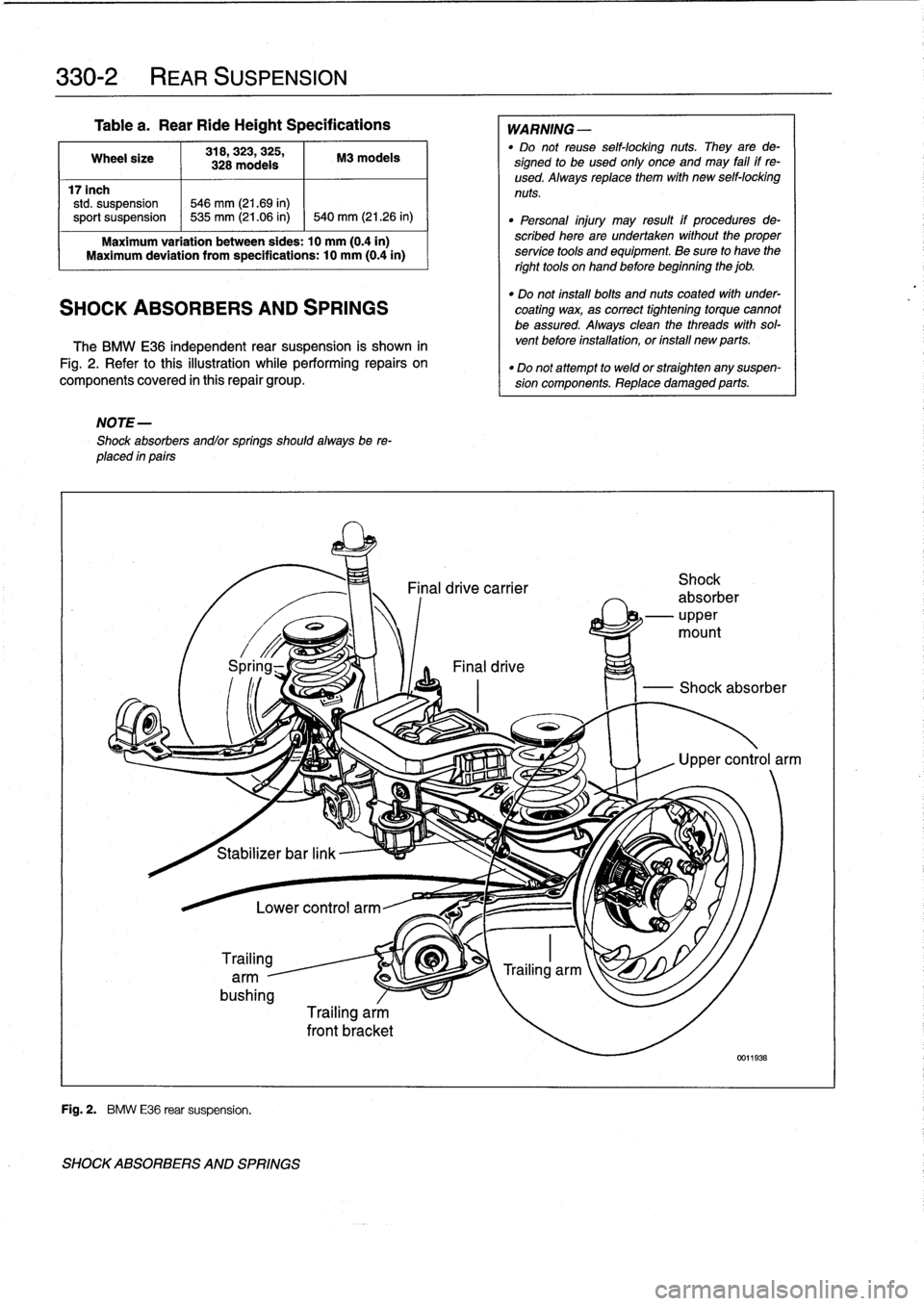
330-2
REAR
SUSPENSION
Table
a
.
Rear
RideHeight
Specifications
Wheel
size
318,323,
325,
M3
modeis
328
modeis
17inch
std
.
suspension
546
mm
(21.69
in)
sport
suspension
~
535
mm
(21.06
in)
1
540
mm
(21
.26
in)
Maximum
variation
between
sides
:
10
mm
(0
.4in)
Maximum
deviation
from
specifications
:
10
mm
(0
.4in)
SHOCK
ABSORBERS
AND
SPRINGS
The
BMW
E36
independent
rear
suspension
is
shown
in
Fig
.
2
.
Refer
tothis
illustration
while
performing
repairs
on
components
covered
in
this
repair
group
.
NOTE-
Shock
absorbers
andlor
springs
shouldalways
be
re-
placed
in
pairs
i
Stabilizer
bar
link
Trailing
arm
-
bushing
Fig
.
2
.
BMW
E36
rear
suspension
.
SHOCK
ABSORBERS
AND
SPRINGS
Lower
control
arm
Trailing
arm
front
bracket
WARNING
-
"
Do
not
reuse
self-locking
nuts
.
They
arede-
signed
to
beused
only
once
and
may
fail
if
re-
used
.
Always
replace
them
with
new
self-locking
nuts
.
"
Personal
injury
may
result
if
procedures
de-
scribed
here
are
undertaken
without
the
proper
service
tools
and
equipment
.
Be
sure
to
have
the
right
tools
onhand
before
beginning
the
job
.
"
Do
not
install
bolts
and
nuts
coated
with
under-
coating
wax,
as
correct
tightening
torque
cannot
be
assured
.
Always
clean
the
threads
with
sol-
vent
before
installation,
or
ínstall
new
parts
.
"
Do
not
attempt
to
weld
or
straighten
any
suspen-
sion
components
.
Replace
damaged
parts
.
Page 287 of 759
GENERAL
......
.
.
.
.
.
.
.
.....
.
.
.
.
.
.
.
.
.
.
331-1
Final
Drive
Oil
Seals
.
.
...
.
.
.
.......
.
.
.
.
.
331-1
Finaldrive
flange
oil
sea¡,
replacing
....
.
.
.
..
331-2
FINAL
DRIVE
SERVICE
.
.....
.
.
.
.
.
.
.
.
.
.
331-1
Finaldrive
inputshaft
oil
seal,
replacing
.
.
.
.
.
331-3
Final
drive
oí¡,
draining
and
filling
.
.
.
.
.
.
.
.
.
.
331-1
Finaldrive
unit,
removíng
and
installing
.
.
.
.
.
.
331-3
GENERAL
This
repa¡r
group
covers
repair
operations
that
do
not
re-
quire
complicated
disassembly
of
the
final
drive
.
Internal
re-
pairs
and
final
drive
disassembly
are
not
covered
in
this
manual
.
FINAL
DRIVE
SERVICE
Al¡
final
drive
work
requires
some
method
of
raising
thecar
and
supporting
it
securely
while
the
work
is
performed
.
Jack
stands
and
a
floor
jack
can
easily
be
used,
but
use
extreme
caution
when
working
beneath
the
car
.
See010
Fundamen-
tais
for
the
Do-It-Yourself
Owner
.
NOTE-
Removal
of
final
drive
carrier
is
covered
in
330
Rear
Suspension
.
Final
drive
oil,
draining
and
filling
1
.
Drive
car
to
warm
final
drive
fluid
.
2
.
Raise
car
and
support
safely
.
WARNING
-
Make
sure
that
thecar
is
firmly
supported
on
jack
standsdesigned
for
the
purpose
.
Place
the
jack
standsbeneatha
structural
chassis
point
.
Do
not
place
jack
stands
under
suspension
parts
.
5
.
Fill
final
drive
with
appropriate
type
and
quantity
of
lu-
bricant
.
Insta¡¡
and
tighten
fill
plug
.
331
Final
Drive
0
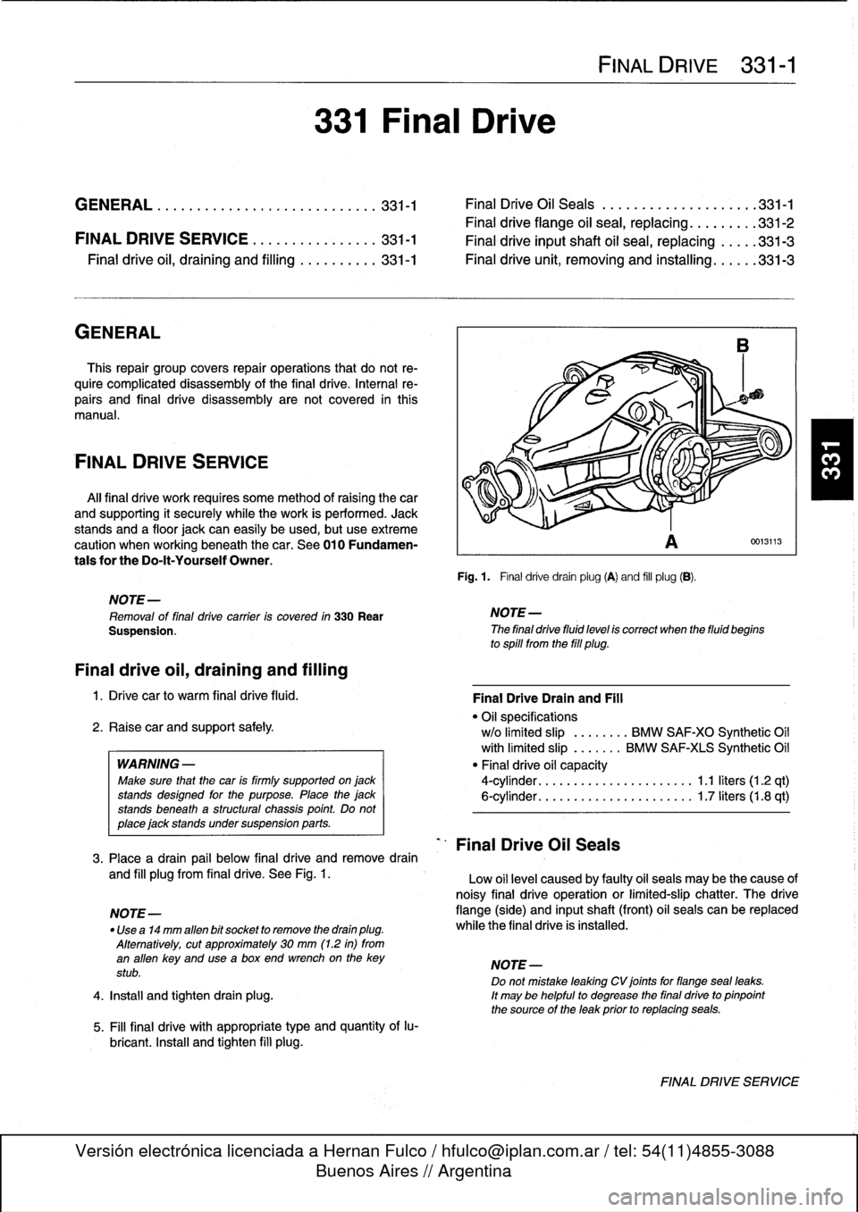
Fig
.
1
.
Final
drivedrain
plug
(A)
and
fill
plug
(B)
.
D
NOTE-
The
final
drive
fluid
level
is
correct
when
the
fluid
begins
to
spill
from
the
fill
plug
.
Final
Drive
Oil
Seals
FINAL
DRIVE
331-1
0013113
Final
DriveDrain
and
Fill
"
Oil
specifications
w/o
limited
slip
.
.......
BMW
SAF-XO
Synthetic
Oil
with
limited
slip
.
......
BMW
SAF-XIS
Synthetic
Oil
"
Final
drive
oil
capacity
4-cylinder
.
.
.
...
................
1
.1
liters
(1
.2
qt)
6-cylinder
.
.
.
...
................
1
.7liters(1.8
qt)
3
.
Place
a
drain
pail
below
final
drive
andremove
drain
and
fill
plugfrom
final
drive
.
See
Fig
.
1
.
Low
oil
level
caused
by
faulty
oil
seals
may
be
the
cause
of
noisy
final
drive
operation
or
limited-slip
chatter
.
The
drive
NOTE-
flange
(side)
and
inputshaft
(front)
oil
seals
can
be
replaced
"
Use
a14
mm
alíen
bit
socket
to
remove
the
drain
plug
.
while
the
final
drive
is
installed
.
Alternatively,
cut
approximately
30
mm
(1
.2
in)
from
an
alíen
key
and
usea
box
end
wrenchon
the
key
NOTE-
stub
.
Do
not
mistake
leaking
CV
joints
for
flangeseal
leaks
.
4
.
Install
and
tighten
drain
plug
.
It
may
be
helpful
to
degrease
the
final
drive
to
pinpoint
the
source
of
the
leak
prior
to
replacing
seals
.
FINAL
DRIVE
SERVICE
Page 288 of 759
331-2
FINAL
DRIVE
Make
sure
that
the
car
is
firm1y
supportedon
Tjack
.
.-
"
:
.-
:
.
n
-
2
.
Detach
drive
axle(s)
from
final
drive
.
See330
Rear
Suspension
.
CA
UTION-
Suspend
the
detached
drive
axlefrom
the
car
body
with
a
stiff
wire
hook
to
prevent
damage
to
the
outer
CV
joint
.
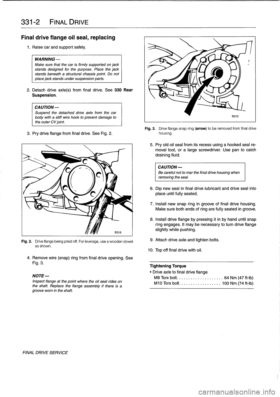
Fig
.
3
.
Drive
flange
snap
ring
(arrow)
to
be
removed
from
final
drive
3
.
Pry
drive
flange
from
final
drive
.
See
Fig
.
2
.
housing
.
Fig
.
2
.
Drive
flange
being
pried
off
.
For
leverage,
use
a
wooden
dowel
as
shown
.
4
.
Remove
wire(snap)
ring
from
final
drive
opening
.
See
Fig
.
3
.
NOTE-
Inspect
flangeat
the
point
where
the
oil
seal
rides
on
the
shaft
.
Replace
the
flange
assembly
if
there
is
agrooveworn
in
the
shaft
FINAL
DRIVE
SERVICE
9
.
Attach
drive
axle
and
tighten
bolts
.
10
.
Top
off
final
drive
with
ofl
.
B315
5
.
Pry
old
oil
sea¡
from
its
recess
using
a
hooked
seal
re-
moval
tool,
or
a
large
screwdriver
.
Use
pan
to
catch
draining
fluid
.
CA
UTION-
Be
careful
not
to
mar
the
final
drive
housing
when
removing
the
sea¡
.
6
.
Dip
new
seal
in
final
drive
lubricant
and
drive
seal
into
place
untilfully
seated
.
7
.
Insta¡¡
new
snap
ringin
groove
of
final
drive
housing
.
Make
sureboth
ends
ofring
are
fully
seated
in
groove
.
8
.
Insta¡¡
drive
flangeby
pressing
it
in
by
hand
until
snap
ring
engages
.
It
may
benecessary
to
turn
drive
flange
slightly
while
pushing
.
Tightening
Torque
"
Drive
axle
to
final
drive
flange
M8
Torx
bolt
..
..................
64
Nm
(47
ft-Ib)
M10
Torx
bolt
.
.................
100
Nm
(74
ft-Ib)
Page 289 of 759
Final
driveinputshaft
oil
sea¡,
replacing
1
.
Raise
car
and
support
safely
.
2
.
Drain
final
drive
oil
as
described
earlier
.
3
.
Remove
driveshaft
from
final
drive
inputshaft
flange
.
See
260
Driveshaft
.
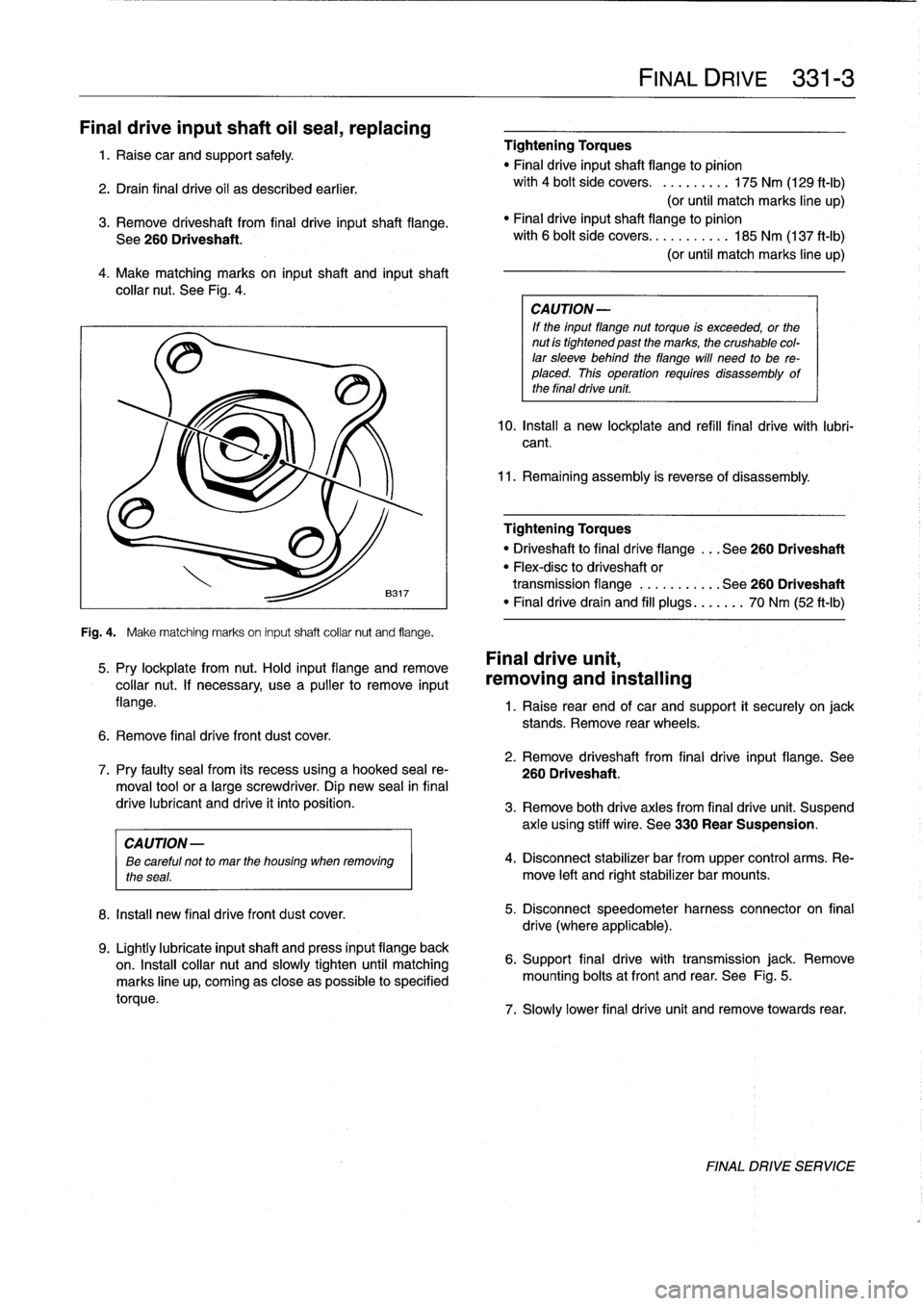
4
.
Make
matching
marks
on
input
shaft
and
inputshaft
collar
nut
.
See
Fig
.
4
.
Fig
.
4
.
Make
matching
marks
on
input
shaft
collar
nut
and
flange
.
5
.
Pry
lockplate
from
nut
.
Hold
input
flange
andremove
collar
nut
.
If
necessary,
usea
pullerto
remove
input
flange
.
6
.
Remove
final
drive
front
dust
cover
.
8
.
Install
new
final
drivefront
dust
cover
.
9
.
Lightly
lubricate
inputshaft
and
press
input
flange
back
on
.
Insta¡¡
collar
nut
and
slowly
tighten
until
matching
marks
line
up,
coming
as
close
aspossible
to
specified
torque
.
Tightening
Torques
"
Final
driveinputshaft
flange
to
pinion
with
4
bolt
side
covers
.
.........
175
Nm
(129
ft-Ib)
(or
until
match
marks
line
up)
"
Finaldriveinputshaft
flange
to
pinion
with
6
bolt
side
covers
...........
185
Nm
(137
ft-Ib)
(or
until
match
marks
line
up)
CA
UTION-
If
the
input
flange
nuttorque
is
exceeded,
or
the
nut
is
tightened
past
the
marks,
the
crushable
col-
lar
sleeve
behind
theflange
will
need
to
be
re-
placed
.
This
operation
requires
disassembly
of
the
final
drive
unit
.
10
.
Install
a
new
lockplate
and
refill
final
drive
with
lubri-
cant
.
11
.
Remaining
assembly
is
reverse
of
disassembly
.
Tightening
Torques
"
Driveshaftto
final
dríve
flange
...
See260
Driveshaft
"
Flex-disc
to
driveshaft
or
transmission
flange
...........
See260
Driveshaft
"
Finaldrivedrain
and
fill
plugs
...
.
..
.
70
Nm
(52
ft-Ib)
Final
drive
unit,
removing
and
installing
FINAL
DRIVE
331-
3
1
.
Raise
rear
end
of
car
and
support
it
securely
on
jack
stands
.
Remove
rear
wheels
.
2
.
Remove
driveshaft
from
final
drive
input
flange
.
See
7
.
Pry
faulty
sea¡
from
its
recess
using
a
hooked
sea¡
re-
260
Driveshaft
.
moval
toolor
a
large
screwdriver
.
Dip
new
sea¡
in
final
drive
lubricant
and
drive
it
into
position
.
3
.
Remove
both
drive
axles
from
final
drive
unit
.
Suspend
axle
using
stiff
wire
.
See
330
Rear
Suspension
.
CAUTION
-
ee
careful
not
to
mar
the
housing
when
removing
4
.
Disconnect
stabilizer
bar
from
upper
control
arms
.
Re-
the
seas
.
move
left
and
rightstabilizer
bar
mounts
.
5
.
Disconnect
speedometer
harness
connector
on
final
drive
(where
applicable)
.
6
.
Support
final
drive
with
transmission
jack
.
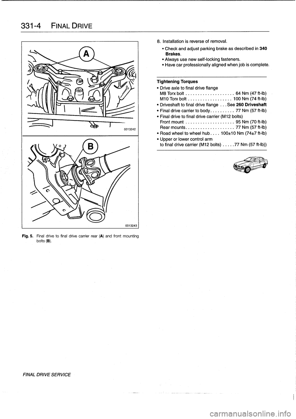
Remove
mounting
bolts
atfront
and
rear
.
See
Fig
.
5
.
7
.
Slowly
lower
final
drive
unit
and
remove
towards
rear
.
FINAL
DRIVE
SERVICE
Page 290 of 759
331-
4
FINAL
DRIVE
FINAL
DRIVE
SERVICE
0013242
0013243
Fig
.
5
.
Final
drive
to
final
drive
carrier
rear
(A)
and
front
mounting
bolts
(B)
.
8
.
Installation
is
reverse
of
removal
.
"
Check
and
adjust
parking
brake
as
described
in
340
Brakes
.
"
Always
use
new
self-locking
fasteners
.
"
Have
car
professionally
aligned
when
job
is
complete
.
Tightening
Torques
"
Drive
axle
to
final
drive
flange
M8
Torx
bolt
..
.
...
...
..
.........
64
Nm
(47
ft-Ib)
M10
Torx
bolt
.
.
...
...
..
........
100
Nm
(74
ft-Ib)
"
Driveshaft
to
final
drive
flange
...
See
260
Driveshaft
"
Final
drive
carrier
to
body
..
........
77
Nm
(57
ft-Ib)
"
Final
drive
to
final
drive
carrier
(M12
bolts)
Front
mount
.....
...
.
...
........
95
Nm
(70
ft-Ib)
Rear
mounts
.....
.......
.
.
.
..
...
77
Nm
(57
ft-Ib)
"
Road
wheel
to
wheel
hub
....
100±10
Nm
(74±7
ft-Ib)
"
Upper
or
lower
control
arm
to
final
drive
carrier
(M12
bolts)
...
..
77
Nm
(57
ft-Ib))
Page 292 of 759
340-2
BRAKES
When
troubleshooting,
keep
in
mind
that
tire
inflation,
wear
and
temperature
can
affect
braking
and
suspension
.
See310
Front
Suspension
for
more
information
on
front
suspension
parts
inspection
.
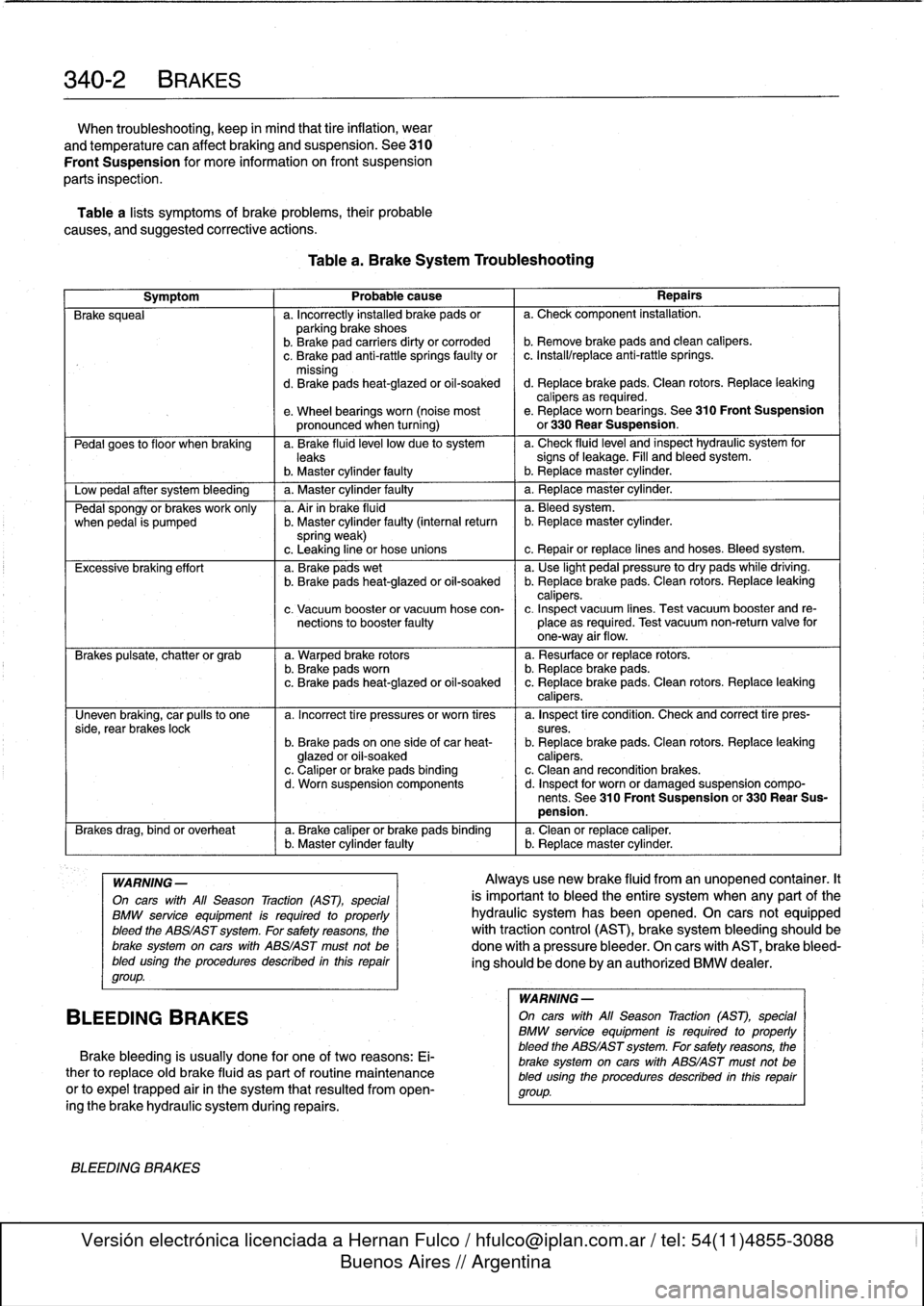
Table
a
lists
symptoms
of
brake
problems,
their
probable
causes,
and
suggested
corrective
actions
.
Table
a
.
Brake
System
Troubleshooting
Symptom
1
Probable
cause
1
Repairs
Brake
squeal
a
.
Incorrectly
installed
brake
pads
or
a
.
Check
component
installation
.
parking
brake
shoes
b
.
Brakepad
carriers
dirty
or
corroded
b
.
Remove
brake
pads
and
clean
calipers
.
c
.
Brake
pad
anti-rattle
springs
faulty
or
c
.
Install/replace
anti-rattle
springs
.
missing
d
.
Brakepads
heat-glazed
or
oil-soaked
d
.
Replace
brake
pads
.
Clean
rotors
.
Replace
leaking
calipers
as
required
.
e
.
Wheel
bearings
worn
(noise
most
e
.
Replace
worn
bearings
.
See310
Front
Suspension
pronounced
when
turning)
or
330
Rear
Suspension
.
Pedal
goes
to
f
loor
when
braking
a
.
Brake
fluid
leve¡
low
due
to
system
a
.
Check
fluidlevel
and
inspect
hydraulic
system
for
leaks
signs
of
leakage
.
Fill
and
bleed
system
.
b
.
Master
cylinder
faulty
I
b
.
Replacemaster
cylinder
.
Low
pedal
after
system
bleeding
1
a
.
Master
cylinder
faulty
1
a
.
Replace
master
cylinder
.
Pedal
spongy
or
brakes
work
only
a
.
Air
in
brake
fluid
a
.
Bleedsystem
.
when
pedal
is
pumped
b
.
Master
cylinder
faulty
(interna¡
return
b
.
Replacemaster
cylinder
.
spring
weak)
c
.
Leaking
line
or
hose
unions
c
.
Repair
or
replace
lines
and
hoses
.
Bleed
system
.
Excessive
braking
effort
a
.
Brake
pads
wet
a
.
Use
light
pedal
pressure
to
dry
pads
while
driving
.
b
.
Brake
pads
heat-glazed
oroil-soaked
b
.
Replace
brake
pads
.
Clean
rotors
.
Replace
leaking
calipers
.
c
.
Vacuum
booster
or
vacuum
hose
con-
c
.
Inspect
vacuum
lines
.
Test
vacuum
booster
and
re
nections
to
booster
faulty
place
as
required
.
Test
vacuum
non-return
valve
for
one-way
air
flow
.
Brakes
pulsate,
chatter
or
grab
a
.
Warped
brake
rotors
a
.
Resurface
or
replace
rotors
.
b
.
Brake
padsworn
b
.
Replace
brake
pads
.
c
.
Brake
pads
heat-glazed
or
oil-soaked
c
.
Replace
brake
pads
.
Clean
rotors
.
Replace
leaking
calipers
.
Uneven
braking,
car
pulís
to
one
a
.
Incorrect
tire
pressures
or
worn
tires
a
.
Inspect
tire
condition
.
Check
and
correct
tire
pres-
side,
rear
brakes
lock
sures
.
b
.
Brake
pads
on
one
side
of
car
heat-
b
.
Replace
brake
pads
.
Clean
rotors
.
Replace
leaking
glazed
or
oil-soaked
calipers
.
c
.
Caliper
or
brake
pads
binding
c
.
Clean
and
recondition
brakes
.
d
.
Worn
suspension
components
d
.
Inspect
for
worn
or
damaged
suspension
compo-
nents
.
See
310
Front
Suspension
or
330
Rear
Sus-
pension
.
Brakes
drag,
bind
or
overheat
a
.
Brake
caliper
or
brake
pads
binding
a
.
Clean
or
replace
caliper
.(
b
.
Master
cylinder
faulty
b
.
Replacemaster
cylinder
.
WARNING
-
On
cars
with
All
Season
Traction
(AST),
special
BMW
service
equipment
is
required
to
properly
bleed
the
ABS/AST
system
.
For
safety
reasons,
the
brake
system
on
carswith
ABS/AST
must
not
be
bled
using
the
procedures
described
inthis
repair
group
.
BLEEDING
BRAKES
Brake
bleeding
is
usually
done
for
one
of
two
reasons
:
Ei-
ther
to
replace
oíd
brake
fluid
as
part
of
routine
maintenance
or
to
expel
trapped
air
in
the
system
that
resulted
from
open-
ingthe
brake
hydraulic
system
during
repairs
.
BLEEDING
BRAKES
Alwaysuse
new
brake
fluid
from
an
unopened
container
.It
is
important
to
bleed
the
entire
system
when
any
part
of
the
hydraulic
system
has
been
opened
.
On
cars
not
equipped
with
traction
control
(AST),
brake
system
bleeding
should
be
done
with
a
pressure
bleeder
.
On
cars
with
AST,
brake
bleed-
ing
should
be
done
by
an
authorized
BMW
dealer
.
WARNING
-
On
cars
with
All
Season
Traction
(AST),
special
BMW
service
equipment
is
requíred
to
properly
bleed
the
ABS/AST
system
.
For
safetyreasons,
the
brake
system
on
carswith
ABS/AST
must
not
be
bled
using
the
procedures
described
inthís
repair
group
.
Page 299 of 759
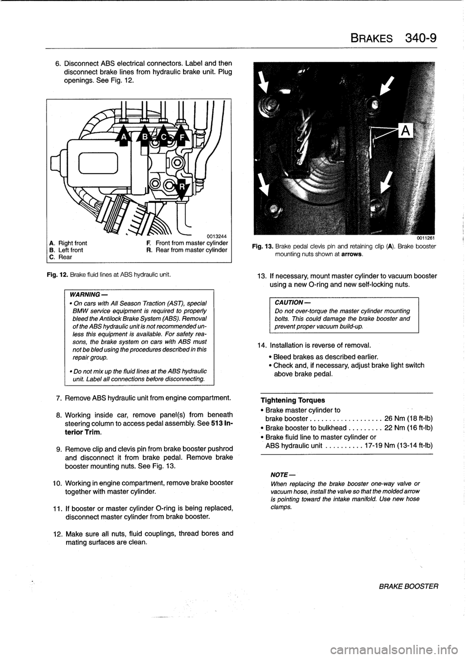
6
.
Disconnect
ABS
electrical
connectors
.
Label
and
then
disconnect
brake
lines
from
hydraulic
brake
unit
.
Plug
openíngs
.
See
Fig
.
12
.
~
~
A
1/
B
'1v
C
~
F
lu
11
-ri
J
.
0013244
A
.
Right
front
F
Front
from
master
cylinder
B
.
Leftfront
R
.
Rear
from
master
cylinder
C
.
Rear
Fig
.
12
.
Brake
fluid
linesat
ABS
hydraulic
unit
.
WARNING
-
"
On
cars
with
All
Season
Traction
(AST),
special
BMW
service
equipment
is
required
to
properly
bleed
the
Antilock
Brake
System
(ABS)
.
Removal
of
the
ABS
hydraulic
unit
is
not
recommended
un-
less
this
equipment
is
available
.
For
safetyrea-
sons,
the
brake
system
on
cars
with
ABS
must
not
be
bled
using
the
procedures
described
inthis
repair
group
.
"
Do
not
mix
up
the
fluid
fines
at
the
ABS
hydraulic
unit
Label
all
connections
before
disconnecting
.
7
.
Remove
ABS
hydraulic
unit
from
engine
compartment
.
8
.
Working
inside
car,
remove
panel(s)
frombeneath
steering
column
to
access
pedal
assembly
.
See513
In-
terior
Trim
.
12
.
Make
sure
al¡
nuts,
fluid
couplings,
thread
bores
and
mating
surfaces
are
clean
.
BRAKES
340-
9
0011261
Fig
.
13
.
Brake
pedal
clevispin
and
retaining
clip
(A)
.
Brake
booster
mounting
nuts
shown
at
arrows
.
13
.
If
necessary,
mount
master
cylinder
to
vacuum
booster
using
a
new
O-ríng
and
newself-locking
nuts
.
CAUTION-
Do
not
over-torque
the
master
cylinder
mounting
bolts
.
This
could
damage
the
brake
booster
and
prevent
proper
vacuum
build-up
.
14
.
Installation
is
reverse
of
Rmoval
.
"
Bleed
brakes
as
described
earlier
.
"
Check
and,
if
necessary,
adjust
brake
light
switch
above
brake
pedal
.
Tightening
Torques
"
Brakemaster
cylinder
to
brake
booster
...........
.
..
..
...
26
Nm
(18
ft-Ib)
"
Brake
booster
to
bulkhead
.
.
..
..
...
22
Nm
(16
ft-Ib)
"
Brake
fluidline
to
master
cylinder
or
ABS
hydraulic
unit
.......
.
..
17-19
Nm
(13-14
ft-lb)
9
.
Remove
clip
and
clevis
pin
from
brake
booster
pushrod
and
disconnect
it
from
brakepedal
.
Remove
brake
booster
mounting
nuts
.
See
Fig
.
13
.
NOTE-
10
.
Working
in
engine
compartment,
remove
brake
booster
When
replacing
the
brake
booster
one-way
valve
or
together
with
master
cylinder
.
vacuum
hose,
install
the
valve
so
that
the
molded
arrow
is
pointing
toward
the
intake
manifold
.
Use
new
hose
11
.
If
booster
or
master
cylinder
O-ring
is
being
replaced,
clamps
.
disconnect
master
cylinder
from
brake
booster
.
BRAKE
BOOSTER
Page 303 of 759
GENERAL
.
....
.
.
.
.
.
.......
.
.
.
.
.
...
.
.
.
400-1
INTERIOR
EQUIPMENT
......
.
.
.
.......
400-4
Seats
and
Seatbelts
.
.
.
.
.
.
.....
.
.
.
.
.
..
.
..
400-4
BODY
ASSEMBLY
.
.
.
.
.
.....
.
.
.
.
.
.
.
.
.
.
.400-2
Instruments
and
Controls
.
..
....
.
.
.
.
.
.
.
...
400-4
Exterior
and
Aerodynamics
....
.
.
.
.
.
.
.
.
.
.
.
400-2
Central
Body
Electronics
.......
.
.
.
...
.
...
400-5
Coupe
Models
..
.
.
.
.
.
.......
.
.
.
.
.
.
.
.
.
..
400-3
Electronic
Immobilization
System
.
.
.
...
.
...
400-5
Convertible
Models
.
.
.
.
.
.
.
.....
.
.
.
.
.
.
.
..
400-3
Heating
and
Air
Conditioning
.
...
.
.
.
.
.
.
.
...
400-6
GENERAL
This
section
covers
system
descriptions
and
general
ser-
vice
information
for
the
repair
groupsfound
in
4
Body
and
5
Body
Equipment
.
When
working
or
servicing
cars
equipped
with
SRS
air-
bag(s),
the
following
precautions
must
be
observed
to
prevent
injury
.
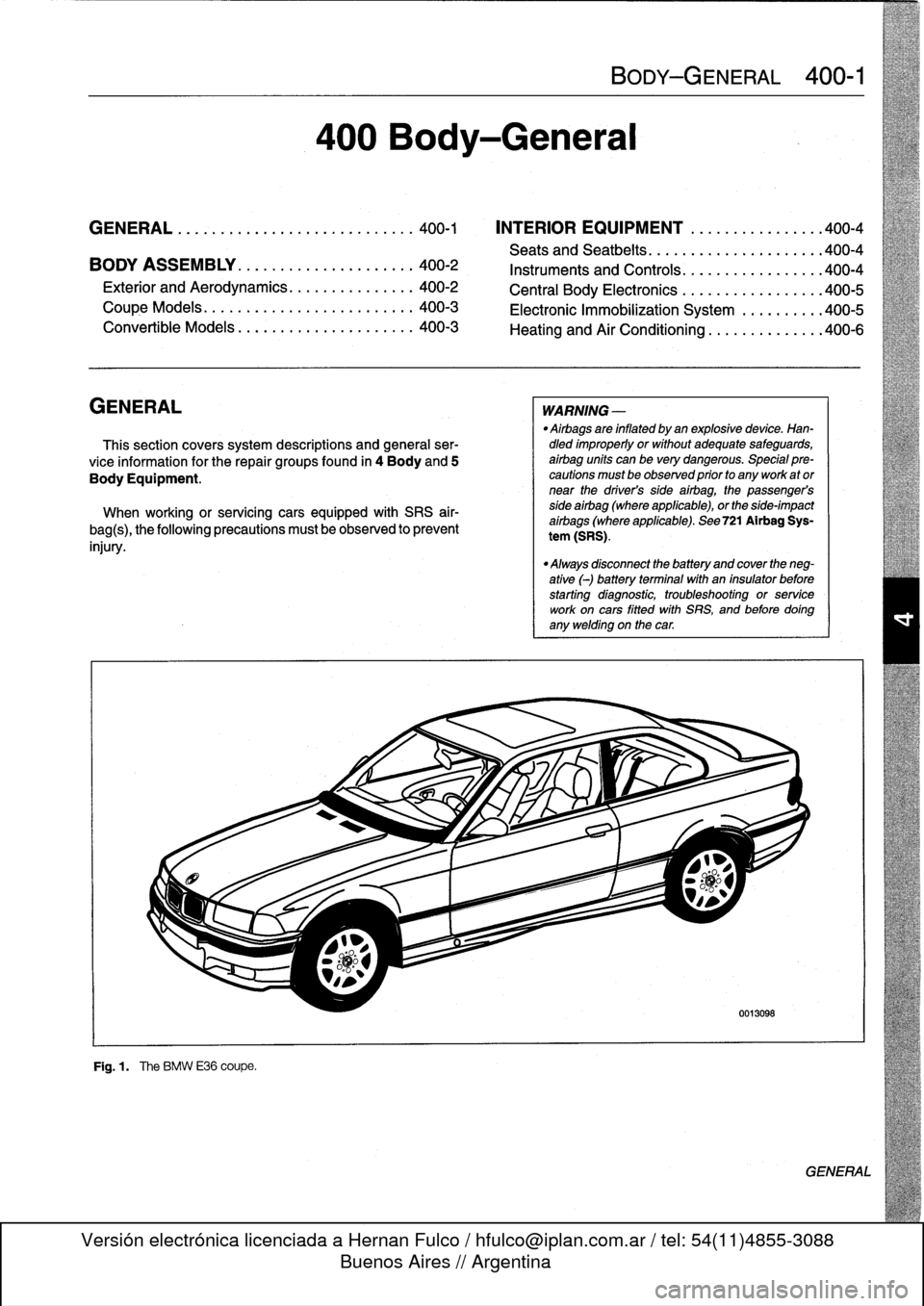
F19
.1
.
The
BMW
E36
coupe
.
400
Body-General
BODY-GENERAL
400-1
WARNING
-
"
Airbags
are
inflated
by
an
explosivedevice
.
Han-dled
improperly
or
without
adequate
safeguards,
airbag
units
can
be
very
dangerous
.
Special
pre-cautions
must
be
observed
prior
to
any
work
ator
near
the
driver's
side
airbag,
the
passenger's
side
airbag
(where
applicable),
or
the
side-impact
aírbags
(where
applicable)
.
See
721
Airbag
Sys-
tem
(SRS)
.
"
Always
disconnect
the
battery
and
cover
the
neg-
ative
(-)
battery
terminalwith
an
insulator
before
starting
diagnostic,
troubleshooting
or
service
work
oncars
fitted
with
SRS,
and
before
doíng
any
welding
on
the
car
.
0013098
GENERAL
Page 306 of 759
400-
4
BODY-GENERAL
INTERIOR
EQUIPMENT
E36
interiors
have
a
unique
character,
with
a
combínation
of
sporty
features
and
innovative
design
.
Al¡
body
versions
were
made
in
a
wide
choice
of
interior
and
exterior
colors
.
New
colors
with
matching
leather
and/or
fabric
upholstery
were
in-
troduced
for
each
model
year,
including
light-alloy
wheels
in
new
designs
.
Driving
comfort
is
enhanced
by
power
steering,
tilt
steering
wheel
(optional),
height-adjustable
front
seats,
and
electrical-
ly
adjustable
and
heated
rear-view
mirrors
.
Inside
thecar
there
are
reading
lights
at
four
seating
positions
.
Seats
and
Seat
Belts
NOTE-
Theseat
base
usedon
cars
with
pyrotechnic
seatbelt
Anatom¡cal
ly-correct
seats
are
constructed
from
polyure-
tensioners
is
not
interchangeable
with
the
earlier
seat
thane
foam
containing
areas
or
"zones"
of
different
firmness
.
base
.
The
seat
bases
have
steel
springs
for
added
support
and
strength
.
The
power
seats
are
provided
with
conveniently
lo-
Instruments
and
Controls
cated
switches
along
the
outside
edge
of
the
seat
.
Heated
seats
are
an
option
in
all
models
.
See
520
Seats
for
more
de-
Everything
in
the
interior
passenger
compartment
essential
tails
.
to
the
driver
is
logically
grouped
and
easy
to
reach
.
Al¡
instru-
ments
and
controls
havebeen
arranged
ergonomically
and
The
M3
sport
seat
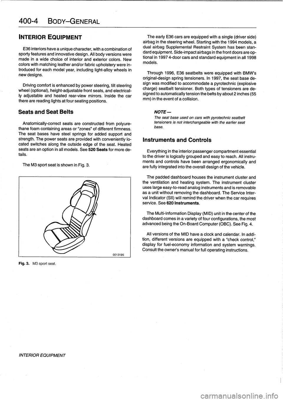
is
shown
in
Fig
.
3
.
are
fully
integrated
into
the
overall
design
of
the
vehicle
.
Fig
.
3
.
M3
sport
seat
.
INTERIOR
EQUIPMENT
0013195
The
early
E36
cars
areequipped
with
a
single
(driver
side)
airbag
in
the
steering
wheel
.
Startingwith
the
1994
models,
a
dual
airbag
Supplemental
Restraint
System
has
been
stan-
dard
equipment
.
Side-impact
airbags
in
the
front
doors
are
op-
tional
in
1997
4-door
cars
and
standard
equipment
in
all
1998
models
.
Through
1996,
E36
seatbelts
were
equipped
with
BMW's
original-designspring
tensioners
.
In
1997,
the
seat
base
de-
sign
was
modified
to
accommodate
a
pyrotechnic
(explosive
charge)
seatbelt
tensioner
.
Both
types
of
tensioners
arede-
signed
to
automatically
tension
the
belts
by
about2
inches(55
mm)
in
the
event
of
a
collision
.
The
padded
dashboard
houses
the
instrument
cluster
and
the
ventilation
and
heating
system
.
The
instrument
cluster
uses
large
easy-to-read
analog
instruments
and
is
removable
as
a
unit
without
removing
the
dashboard
.
The
Service
Inter-
val
Indicator
(SII)
will
remind
the
driver
when
thecar
requires
service
.
See
620
Instruments
.
The
Multi-Information
Display
(MID)
unit
in
thecenter
of
the
dashboard
comes
in
a
variety
of
four
configurations,
the
most
advanced
being
the
On-Board
Computer
(OBC)
.
See
Fig
.
4
.
Al¡
versions
of
the
MID
have
a
clock
and
calendar
.
In
addi-
tion,
different
versions
areequipped
with
a
"check
control,"
display
for
fuel-economy
information
and
system
warnings
.
Consult
the
owner's
manual
for
fui¡
operating
instructions
.
Page 309 of 759
GENERAL
This
repair
group
covers
replacement
of
the
front
fenders
and
removal
and
installation
of
the
engine
hood
.
NOTE-
The
body
is
painted
at
the
factoryafter
assembly
.
Re-
alignment
of
body
panels
may
expose
unpainted
metal
.
Paint
all
exposed
metal
once
the
work
fs
complete
.
FRONT
FENDERS
Front
fender,
removing
and
installing
1
.
Raise
hood
.
Raise
and
safely
support
front
of
vehicle
.
WARNING
-
"
When
raising
thecar
using
a
floor
jack
or
a
hy-
draulic
lift,
carefully
position
the
jack
pad
to
pre-
vent
damaging
thecar
body
.
A
suitable
liner
(wood,
rubber,
etc
.)
should
be
placed
between
the
jack
and
the
car
to
prevent
body
damage
.
"
Watch
the
jack
closely
.
Make
sure
it
stays
stable
and
does
not
shift
or
tilt
.
As
the
car
is
raised,
the
car
may
roll
slightly
and
the
jack
may
shift
.
2
.
Remove
front
wheel
.
Remove
inner
plastic
liner
from
wheel
well
.
3
.
Remove
front
bumper
.
See510
Exterior
Trim,
Bumpers
.
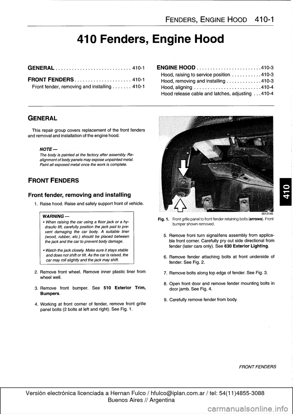
4
.
Working
atfront
corner
of
fender,
remove
front
grille
panel
bolts
(2
bolts
at
left
and
right)
.
See
Fig
.
1
.
FENDERS,
ENGINE
HOOD
410-1
410
Fenders,
Engine
Hood
GENERAL
...............
.
.
.
.
.
.
.
.
.
.
.
..
410-1
ENGINE
HOOD
.
.
.
.
.
.
.
.
.
.
.
.
.
.
.
.
.
.
.
...
.
.410-3
Hood,
raising
to
service
position
.
.
.
.
.
.
.
.
...
410-3
FRONTFENDERS
........
.
.
.
.
.
.
.
.
.
.
.
.
.410-1
Hood,
removin
and
installin
410-3
Front
Pender,
removing
and
installing
.
.
.
....
410-1
Hood,
aligning
...
.
.
.
.
.
.
.
.....
.
.
.
.
.
.
.
...
410-4
Hood
release
cable
and
latches,
adjusting
...
410-4
001
.145
Fig
.
1
.
Front
grille
panel
to
front
fender
retaining
bolts
(arrows)
.
Front
bumpershown
removed
.
5
.
Remove
front
turn
signalliens
assembly
from
applica-
ble
front
corner
.
Carefully
pryout
side
directional
from
fender
(later
cars
only)
.
See
630
Exterior
Lighting
.
6
.
Remove
fender
attaching
bolts
atfront
underside
of
fender
.
See
Fig
.
2
.
7
.
Remove
bolts
along
top
edge
of
fender
:
See
Fig
.
3
.
8
.
Open
front
door
and
remove
fender
mounting
bolts
in
door
jamb
.
See
Fig
.
4
.
9
.
Carefully
remove
fender
from
body
.
FRONTFENDERS