wheel bolt torque BMW 318i 1997 E36 User Guide
[x] Cancel search | Manufacturer: BMW, Model Year: 1997, Model line: 318i, Model: BMW 318i 1997 E36Pages: 759
Page 112 of 759
117-
1
6
CAMSHAFT
TIMING
CHAIN
15
.
Remove
crankshaft
locking
tool
.
Remove
special
test
equipment
.
Insta¡¡
oil
supply
line
using
new
seals
and
reconnect
solenoid
connector
.
Remainder
of
installa-
tion
is
reverse
of
removal
.
Tightening
Torque
"
Cylinder
head
cover
to
cylinder
head
.
10
Nm
(89
in-lb)
"
VANOS
oil
supply
line
to
VANOS
control
unit
(banjo
bolt)
..
.........
32
Nm
(24
ft-Ib)
"
VANOS
solenoidlo
VANOS
control
unit
........
.
.
.
..
........
30
Nm
(22
ft-Ib)
VANOS
control
unit,
removing
Special
BMW
service
tools
are
required
lo
remove
and
in-
stall
the
VANOS
control
unit
.
Read
the
procedure
through
be-
forestarting
the
job
.
1
.
Remove
radiator
cooling
fan
shroud
and
cooling
fan
.
See
170
Radiator
and
Cooling
System
.
CAUTION-
Radiator
fan
has
left
hand
threads
.
2
.
Remove
top
plastic
engine
covers
.
Disconnect
ignition
coil
harness
connectors
from
coils
.
Remove
ignition
coils
.
Remove
cylinder
head
cover
.
Unclip
andremove
oil
baffle
cover
from
above
intake
camshaft
.See
113
Cylinder
Head
Removal
and
Installation
.
NOTE-
Make
note
of
the
mounting
bolt
insulator
arrangement
during
removal
of
the
cylinder
head
cover
.
3
.
Set
engine
lo
TDC
by
rotating
engine
in
normal
operat-
ing
direction
until
camshaft
lobes
at
cylinder
no
.
1
are
facing
each
other
and
"0/T"
mark
(0°TDC)
on
vibration
damper
lines
up
with
cast
boss
on
lower
timing
chain
cover
.
See
Fig
.
38
.
4
.
Lock
crankshaft
at
TDC
by
inserting
BMW
special
tool
no
.
11
2
300
through
transmission
bellhousing
and
finto
flywheel
or
drive
plate
.
Refer
to
Fig
.
36
given
earlier
.
NOTE-
Confirm
that
the
locking
tool
has
been
correctly
in-
stalled
by
trying
to
rotatethe
crankshaft
.
5
.
Remove
three
cylinder
head
cover
mounting
studs
from
rear
of
head
.
Lockcamshafts
at
TDC
bymounting
BMW
special
tool
no
.
11
3
240
at
ends
of
camshafts
.
Check
that
tool
is
squarely
seated
on
cylinder
head
gasket
surface
.
If
necessary,
rotate
camshafts
slightly
using
a24
mm
wrench
.
Refer
to
Fig
.
24
given
earlier
.
VANOS
(VARIABLE
VALVE
TIMING)
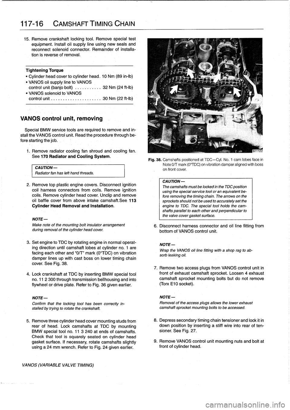
Fig
.
38
.
Camshafts
positioned
at
TDC-Cyl
.
No
.
1
cam
lobes
face
in
Note
0/T
mark
(0°TDC)
on
vibration
damper
alígned
with
boss
on
front
cover
.
CA
UTION-
Thecamshafts
mustbe
locked
in
the
TDC
position
using
the
specialservice
tool
or
an
equivalent
be-
fore
removing
the
timing
chain
.
Thearrows
on
the
sprockets
should
not
be
used
to
accurately
set
the
engine
to
TDC
The
special
tool
holds
the
cam-
shafts
parallel
to
each
other
and
perpendicular
to
the
valve
cover
gasket
surface
.
6
.
Disconnect
harness
connector
and
oil
line
fitting
from
bottom
of
VANOS
control
unit
.
NOTE-
Wrap
the
VANOS
oilfine
fitting
with
a
shop
rag
to
ab-
sorb
leaking
oil
.
7
.
Remove
two
access
plugs
from
VANOS
control
unit
in
frontof
exhaustcamshaft
sprocket
.
Loosen
4exhaustcamshaft
sprocket
mounting
bolts
but
do
not
remove
(Torx
El
0
socket)
.
NOTE-
Removal
of
the
access
plugs
allows
the
lower
exhaust
camshaft
sprocket
mounting
bolts
to
be
accessed
.
8
.
Depress
secondary
timing
chain
tensioner
and
lock
it
in
down
position
by
inserting
a
stiff
wire
into
rear
of
ten-
sioner
.
See
Fig
.
27
.
9
.
Remove
VANOS
control
unít
mounting
nuts
and
boltat
front
of
cylinder
head
.
Page 114 of 759
117-
1
8
CAMSHAFT
TIMING
CHAIN
CAUTION-
It
is
crítical
that
the
exhaustcamshaft
sprocket
be
turned
only
the
mínimum
amount
necessary
to
engage
the
gear
cup
.
If
this
procedure
is
done
ín-
correctly,
the
VANOS
system
may
not
function
throughout
íts
full
range
.
NOTE-
As
the
control
unit
isinstalled,
the
secondary
sprockets
will
rotate
in
the
counterclockwise
direction
.
It
may
be
necessary
to
guide
sprockets
counterclockwise
as
the
control
unit
is
installed
.
8
.
On
cars
built
from3/95
:
Use
a
spanner
tool
(See
Fig
.
39
.),
turn
exhaust
sprocket
counterclockwise
(as
víewed
from
front
of
engine)
only
enough
to
mesh
gear
cup
splines
with
camshaftgear
.
Slowly
push
VANOS
control
unit
towards
camshaft
until
it
is
fully
seated,guiding
chains
in
counterclockwise
direction
.
CA
UTION-
Ensure
that
the
first
available
tooth
engages
.
9
.
Install
and
tightencontrol
unit
nuts
and
bolt
.
10
.
Connect
harness
connector
to
VANOS
solenoid
.
Using
new
seals,
insta¡¡
oil
line
fitting
.
Tightening
Torques
"
VANOS
control
unitto
cylinder
head
M6
nut
.....
..
..
.
.
.............
10
Nm
(89
in-lb)
M8
bolt
.....
.
.
.
.
..
.............
22
Nm
(17
ft-Ib)
"
VANOS
oil
supply
line
to
control
unit
.
32
Nm
(24
ft-Ib)
11
.
Slowlyunlock
and
release
secondary
chain
tensioner
.
12
.
Preloadprimary
chain
by
tightening
BMW
special
tool
no
.
112
240
(dummy
chain
tensioner)
to
1
.3
Nm
(11
in-
lb)
.
Then
tighten
exhaust
camshaft
sprocket
mounting
bolts
alternately
in
two
stages
.
Tightening
Torque
"
Secondarytiming
chain
sprockets
to
camshafts
(Tora
boits)
Stage
1
..
...............
...
.
.
...
5
Nm
(44
in-lb)
Stage
2
..
...............
...
.
.
..
22
Nm
(17
ft-Ib)
VANOS
(VARIABLE
VALVE
TIMING)
13
.
Remove
flywheel
locking
tool
from
transmission
bell-
housing
.
Remove
camshaft
locking
tool
from
rear
of
cylinder
head
.
14
.
Turn
engine
over
by
hand
at
least
two
fui¡
crankshaft
ro-
tations
.
Reinstall
camshaft
locking
tool
and
flywheel
locking
toolto
make
sure
all
adjustments
are
correct
.
If
settings
are
correct,
remove
locking
tools
.
15
.
Remove
BMW
special
tool
112
420
(dummy
chain
ten-
sioner)
from
side
of
cylinder
head
.
Install
primary
chain
tensioner
so
that
cutout
in
tensioner
piston
engages
chain
rail
.
See
Fig
.
34
.
Using
new
seals,
install
and
tighten
access
plugs
in
VANOS
control
unit
.
Tightening
Torque
"
Access
plugs
to
VANOS
control
unit
.
..
.
.....
.
..
...
50
Nm
(37
ft-lb)
"
Primary
timing
chain
tensioner
plug
to
tensioner
sleeve
M50/S50USengine
.
.
..
.
.
...
.
...
..
50
Nm
(37
ft-Ib)
M52/S52US
engine
...
..
...
...
...
40
Nm
(30
ft-Ib)
16
.
Install
oil
baffle
cover
above
intake
camshaft
.
Install
three
cylinder
head
covermounting
studs
to
rear
of
head
.
Instali
cylinder
head
cover
.
Tightening
Torque
"
Cylinder
head
cover
to
cylinder
head
(M6
screws)
......
10
Nm
(89
in-Ib)
17
.
Installationof
remaining
parts
is
reverse
of
removal
.
NOTE-
Be
sure
to
install
the
ground
wíres
at
the
cylinder
head
cover
mounting
studs
and
at
the
front
of
the
cylinder
head,
if
applicable
.
Page 118 of 759
119-
4
LUBRICATION
SYSTEM
15
.
Remove
oil
pan
screws
.
Lower
andremove
oil
pan
to-
ward
rear
.
Tightening
Torques
"
Control
arm
bushing
carrier
CAUTION-
to
body(M10
bolt)
...............
42
Nm
(31
ft-Ib)
'
lf
the
oil
pan
does
not
separate
easily
from
the
en-
"
Engine
mount
to
gine
cylinder
block,
make
sure
all
mounting
bolis
suspension
crossmember
(M10
nut)
.
42
Nm
(31
ft-Ib)
have
been
removed
.
If
necessary,
a
few
tapswith
"
Front
suspension
crossmember
a
rubber
mallet
shouldbreak
it
free
.
Never
pry
the
to
body
.
.
..
...
..
.
....
See
310
Front
SusPension
oil
pan
loose
.
"
Oil
pan
to
engine
block
(M6
bolt)
8
.8
grade
..
....
.
...
...
.
........
10
Nm
(89
in-lb)
16
.
Installation
is
reverse
of
removal
.
10
.9
grade
...
..
.
....
..
.
.
.
.......
12
Nm
(9
ft-Ib)
"
Thoroughly
clean
all
old
gasket
material
from
mating
"
Power
steering
pump
to
bracket
surfaces
anduse
a
new
gasket
.
(self-locking
nuts)
....
..
.
....
..
.
..
22
Nm
(16
ft-Ib)
"
Applya
small
amount
of
non-hardening
sealer
(3-
"
Power
steering
pump
bracket
to
engine
Bond
O
l209
or
equivalent)
to
oil
pan
gasket
directly
block
or
oil
pan
(self-locking
nuts)
..
.
22
Nm
(16
ft-Ib)
below
joints
for
end
cover
and
front
timing
case
cover
.
"
Stabilizer
bar
link
to
control
arm
See
Fig
.
5
.
M8
nut
.................
...
.
...
22
Nm
(17
ft-Ib)
"
When
installing
oil
pan
to
engine,
tighten
forward
M10
nut
.....................
..
42
Nm
(31
Ib-ft)
screws
first,
then
tightenrear
.
"
Steering
column
universal
joint
"
Fill
engine
with
oil
as
described
in
020
Maintenance
to
steering
rack
spindle
(M8
bolt)
....
19
Nm
(14
ft-ib)
Program
.
0011950
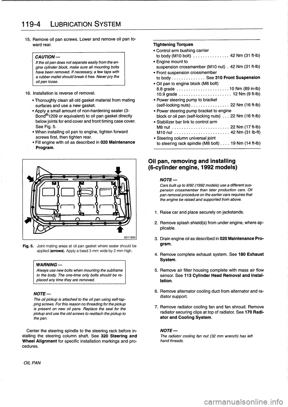
Fig
.
5
.
Joint-mating
areas
at
oil
pan
gasket
where
sealer
should
be
applied
(arrows)
.
Apply
a
bead
3
mm
wideby
2
mm
high
.
OIL
PAN
WARNING
-
Always
use
new
bolis
when
mounting
the
subframe
to
the
body
.
The
one-timeonly
bolis
shouldbe
re-
placed
any
timethey
are
removed
.
NOTE-
The
oil
pickup
is
attached
to
the
oil
pan
using
self-tap-
ping
screws
.
For
this
reasonno
threading
for
the
pickup
is
present
on
new
oil
pans
.
Replace
the
seal
for
the
pickup
and
use
the
oíd
screws
to
rea
ttach
the
pickup
to
the
pan
.
Oil
pan,
removing
and
installing
(6-cylinder
engine,
1992models)
NOTE-
Cars
built
up
to
9/92
(1992models)usea
different
sus-
pension
crossmember
than
later
production
cars
.
Oil
pan
removalprocedureon
the
earlier
cars
requires
that
the
engine
be
raised
and
supportedfrom
above
.
1
.
Raise
car
and
place
securely
on
jackstands
.
2
.
Remove
splash
shield(s)
from
under
engine,
where
ap-
plicable
.
3
.
Drain
engine
oil
as
described
in
020
Maintenance
Pro-
gram
.
4
.
Remove
complete
exhaust
system
.
See180
Exhaust
System
.
5
.
Remove
air
filter
housing
complete
with
mass
air
flow
sensor
.
See
113
Cylinder
Head
Removal
and
Instal-
lation
.
6
.
Remove
alternator
cooling
duct
from
alternator
and
ra-
diator
support
.
7
.
Remove
radiator
cooling
fan
and
fan
shroud
.
Remove
radiator
securing
clips
at
top
of
radiator
.
See
170
Radi-
ator
and
Cooling
System
.
Center
the
steering
spindle
to
the
steering
rack
before
in-
NOTE-
stalling
the
steering
column
shaft
.
See
320
Steering
and
The
radiator
cooling
fan
nut(32
mm
wrench)
has
left
Wheel
Alignment
for
specific
installation
markings
and
pro-
hand
threads
.
cedures
.
Page 122 of 759
119-
8
LUBRICATION
SYSTEM
17
.
Installation
is
reverse
of
removal
.
"
Thoroughly
clean
all
old
gasket
material
from
mating
surtaces
anduse
a
new
gasket
.
"
Applya
small
amount
of
non-hardening
sealer
(3-Bond
1209
0
or
equivalent)
to
oil
pan
gasket
directly
below
joints
for
and
cover
and
front
timing
case
cover
.
See
Fig
.
12
.
"
Tighten
oil
pan
bolts
starting
at
front
first,
working
to-
wardback
(transmission)
end
.
"
Fill
engine
with
oil
as
described
in
020
Maintenance
Program
.
"
After
addingengine
oil,
start
and
run
engine
.
Raiseen-
gine
speed
to
2,500
rpm
until
oíl
pressure
warning
lampgoes
out
(about
5seconds)
.
OIL
PUMP
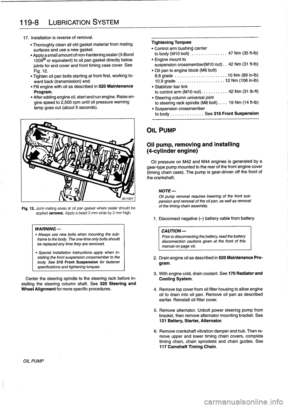
applied
(arrows)
.
Apply
a
bead
3
mm
wideby
2
mm
high
.
WARNING
-
"
Always
use
new
bolts
when
mounting
the
sub-
frame
to
the
body
.
The
one-time
only
bolts
should
be
replaced
any
timethey
are
removed
.
"
Special
installation
instructions
apply
when
in-
stalling
the
front
suspension
crossmember
to
the
body
.
See
310
Front
Suspension
for
fastener
specifications
and
tightening
torques
.
Fig
.
12
.
Joint-mating
areas
at
oil
pan
gasket
where
sealer
should
be
Center
the
steering
spindle
to
the
steering
rack
before
in-
stalling
the
steering
column
shaft
.
See
320
Steering
and
Wheel
Alignment
for
more
specific
procedures
.
Tightening
Torques
"
Control
arm
bushing
carrier
to
body
(M10
bolt)
...............
47
Nm
(35
ft-Ib)
"
Engine
mount
to
suspension
crossmember(M10
nut)
..
42
Nm
(31
ft-Ib)
"
Oil
pan
to
engine
block
(M6
bolt)
8
.8
grade
...........
.......
....
10
Nm
(89
in-lb)
10
.9
grade
...........
..
...
...
.
12
Nm
(106
in-lb)
"
Stabilizer
bar
link
to
control
arm
(M10
nut)
.......
....
42
Nm
(31
Ib-ft)
"
Steering
column
universal
joint
to
steering
rack
spindle
(M8
bolt)
....
19
Nm
(14
ft-Ib)
"
Suspensíon
crossmember
to
body
...
...
.
...
..
.
.
See
310
Front
Suspension
OIL
PUMP
Oil
pump,
removing
and
installing
(4-cylinder
engine)
Oil
pressure
on
M42
and
M44
engines
is
generatedbya
gear-type
pump
mounted
to
the
rear
of
the
front
engine
cover
(timing
chaincase)
.
The
pump
is
gear-driven
off
the
front
of
the
crankshaft
.
NOTE-
Oil
pump
removal
requires
lowering
of
the
front
sus-
pension
and
removal
of
the
oil
pan,
as
well
asremoval
of
the
timing
chain
assembly
.
1
.
Disconnect
negative
(-)
battery
cable
from
battery
.
CAUTION-
Prior
to
disconnectiog
the
battery,
read
the
battery
disconnection
cautions
given
at
the
front
of
this
manual
on
paga
vÍii
.
2
.
Drain
engine
oil
as
described
in
020
Maintenance
Pro-
gram
.
3
.
Withengine
cold,
drain
coolant
.
See
170
Radiator
and
Cooling
System
.
4
.
Remove
top
cover
from
oil
filter
housing
to
allow
engine
oil
to
drain
into
oil
pan
.
Remove
oil
pan
as
described
earlier
.
Reinstall
oil
filter
cover
.
5
.
Remove
alternator
.
Unbolt
power
steering
pump
from
bracket,
then
remove
alternator
mountíng
bracket
.
See
121
Battery,
Starter,
Alternator
.
6
.
Remove
crankshaft
vibration
damper
andhub
.
Then
re-
move
upper
and
lower
timing
chain
covers,
complete
timingchain,
chain
sprockets
and
chain
guides
.
See
117
Camshaft
Tíming
Chain
.
Page 130 of 759
120-
6
IGNITION
SYSTEM
Crankshaft
position/rpm
sensor,
testing
and
replacing
(front
mounted)
1
.
Disconnect
sensor
harness
connector
.
2
.
Using
a
digital
multimeter,
check
resistance
between
terminals
1
and
2
in
connector
.
See
Fig
.
10
.
n1
n2n3
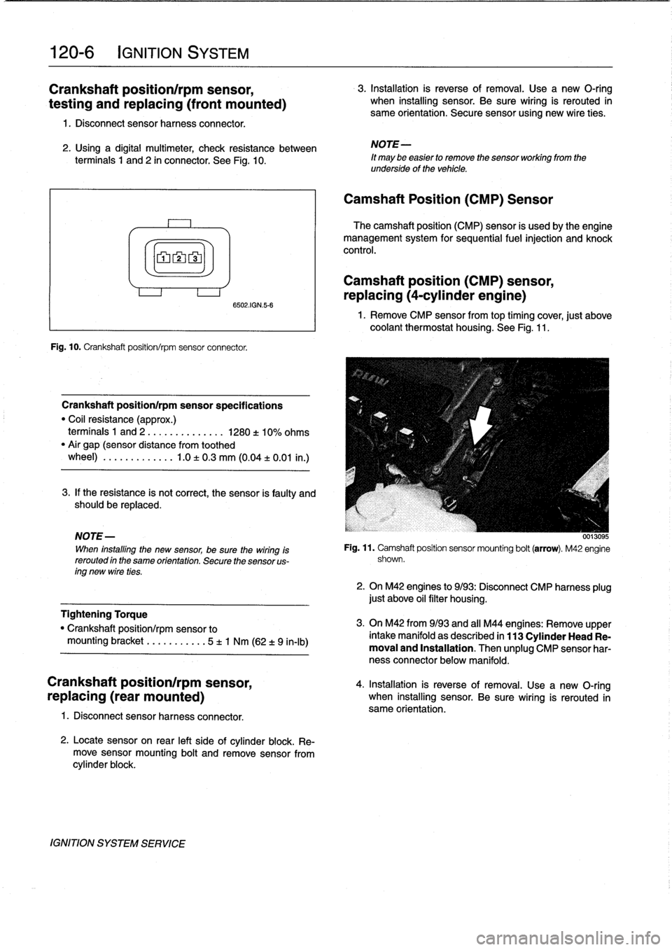
Fig
.
10
.
Crankshaft
position/rpm
sensorconnector
.
Crankshaft
positionlrpm
sensor
specifications
"
Coil
resistance
(approx
.)
terminais
1
and
2
....
.
..
...
....
1280
±
10%
ohms
"
Air
gap
(sensor
distance
from
toothed
wheel)
..
.
.
........
.1
.0
±
0
.3
mm
(0
.04
±
0
.01
in
.)
3
.
If
the
resistance
is
not
correct,
the
sensor
is
faulty
and
should
be
replaced
.
NOTE
-
When
installing
the
new
sensor,
be
sure
thewiring
Is
rerouted
in
the
same
orientation
.
Secure
the
sensor
us-
ing
new
wire
ties
.
Tightening
Torque
"
Crankshaft
position/rpm
sensor
to
mounting
bracket
.........
.
.
5
t
1
Nm
(62
t
9
in-lb)
Crankshaft
position/rpm
sensor,
4
.
Installation
is
reverse
of
removal
.
Use
a
new
O-ring
replacing
(rear
mounted)
when
installing
sensor
.
Be
sure
wiring
is
rerouted
in
same
orientation
.
1
.
Disconnect
sensor
harness
connector
.
6502AGN56
2
.
Locatesensor
on
rear
left
sideof
cylinder
block
.
Re-
move
sensormounting
bolt
and
remove
sensorfrom
cylinder
block
.
IGNITION
SYSTEM
SERVICE
3
.
Installation
is
reverse
of
removal
.
Use
a
new
O-ring
when
installing
sensor
.
Be
sure
wiring
is
rerouted
in
same
orientation
.
Secure
sensor
using
new
wire
ties
.
NOTE-
It
may
be
easier
to
remove
the
sensor
working
from
the
underside
of
the
vehicle
.
Camshaft
Position
(CMP)
Sensor
The
camshaft
position
(CMP)
sensor
is
usedby
the
engine
management
system
for
sequential
fuel
injection
and
knock
control
.
Camshaft
position
(CMP)
sensor,
replacing
(4-cylinder
engine)
1
.
Remove
CMP
sensorfromtop
timing
cover,
just
above
coolantthermostat
housing
.
See
Fig
.
11
.
Fig
.
11
.
Camshaft
position
sensor
mounting
bolt
(arrow)
.
M42
engine
shown
.
2
.
On
M42
engines
to
9/93
:
Disconnect
CMP
harness
plug
just
above
oil
filter
housing
.
3
.
On
M42
from9/93
and
all
M44
engines
:
Remove
upper
intake
manifold
as
described
in
113
Cylinder
Head
Re-
moval
and
Installation
.
Then
unplug
CMP
sensor
har-
ness
connector
below
manifold
.
Page 144 of 759
121-
8
BATTERY,
STARTER,
ALTERNATOR
1f
the
solenoid
audibly
cliicks
but
the
motor
does
not
turn,
Starter,
removing
and
installing
switch
on
the
lights
andtum
the
key
to
the
start
position
.
lf
the
(6-cylinder
engine
with
lights
go
out
while
attempting
to
start,
the
battery
cable
may
be
manual
transmission)
loose
or
the
starter
may
have
a
short
circuit
.
If
the
lights
stay
on,the
solenoid
is
most
likely
atfault
.
The
starter
on
a
6-cylinder
car
with
manual
transmission
is
Starter,
removing
and
installing
(4-cylinder
engine)
1
.
Disconnect
negative
(-)
battery
cable
.
1
.
Disconnect
negative
(-)
cable
from
battery
.
CAUTION-
Prior
to
disconnecting
the
battery,
read
the
battery
disconnection
cautions
given
at
the
front
of
this
manual
on
page
viii
.
2
.
Remove
guide
tube
for
oil
dipstick
.
3
.
Raise
vehicle
.
WARNING
-
Make
sure
the
car
ís
stable
and
wefl
supported
at
all
times
.
Use
a
professional
automotive
lift
or
jack
stands
designed
forthe
purpose
.
A
floor
jack
is
not
adequate
support
.
4
.
Disconnect
wiring
from
starter
.
5
.
Remove
top
and
bottom
starter
bolts
.
Bottom
bolt
must
be
removed
from
below
car
.
Remove
starter
support
bracket,
if
applicable
.
removed
from
below
.
2
.
Raise
vehicle
.
3
.
Remove
reinforcing
cross
bracefromunder
transmís-
sion,
if
applicable
.
4
.
Remove
cover
from
fuel
filter
and
fuel
lines
on
left
side
underneath
car,
if
applicable
.
Detach
fuel
lines
and
har-
ness
connectors
from
retainingbrackets,
as
necessary
5
.
Disconnect
wiring
from
starter
.
6
.
Loosen
andremove
bolts
and
nuts
fastening
starter
to
transmission
bell
housing
and/or
engine
block
.
Remove
starter
supportbracket
.
7
.
Remove
starter
from
below
.
8
.
Check
starter
pinion
gear
and
flywheel
teeth
for
dam-
age
.
9
.
Installation
is
reverse
of
removal
.
6
.
Pull
starter
downward
and
turn
until
solenoid
is
at
top,
Tightening
Torques
then
remove
from
car
.
"
Re¡
nforcing
cross
brace
to
chassis
(M10)
..
...............
42
Nm
(31
ft-Ib)
7
.
>Check
starter
pinion
gear
and
flywheel
teeth
for
dam-
"
Starter
to
engine
block
(M10
bolt)
...
50
Nm
(37
ft-Ib)
age
.
"
Support
bracket
to
starter
(M5
nut)
...
5
Nm
(44
in-lb)
"
Support
bracket
8
.
Installation
is
reverse
of
removal
.
to
engine
block
(M10
bolt)
.........
47
Nm
(35
ft-Ib)
"
Wire
to
terminal
50
(M6
nut)
.........
6
Nm
(53
ín-Ib)
"
Wire
to
terminal
30
(M8
nut)
.........
12
Nm
(9
ft-lb)
Tightening
Torques
"
Starter
to
engine
block
(M10
bolt)
...
50
Nm
(37
ft-lb)
Wire
to
terminal
50
(M6
nut)
........
6
Nm
(53
in-lb)
"
Wire
toterminal
30
(M8
nut)
...
,
..:.
12
Nm
(9
ft-Ib)
STARTER
SERVICE
Page 146 of 759
121-1
O
BATTERY,
STARTER,
ALTERNATOR
9
.
Remove
starter
from
above
.
10
.
Check
starter
pinion
gear
and
flywheel
teeth
for
dam-
age
.
11
.
Installation
is
reverse
of
removal
.
Tightening
Torques
"
tntakemanifold
to
cylinder
head
M7
nut
...
.
................
...
.
15
Nm
(11
ft-Ib)
M8
nut/bolt
.............
.
.
..
...
22
Nm
(16
ft-Ib)
"
Starter
to
engine
block
(M10
bolt)
...
50
Nm
(37
ft-Ib)
"
Support
bracket
to
starter
(M5
nut)
...
5
Nm
(44
in-lb)
"
Support
bracket
to
engine
block
(M10
bolt)
.
.
..
..
...
47
Nm
(35
ft-Ib)
"
Wire
toterminal
50
(M6
nut)
.
..
.....
6
Nm
(53
in-lb)
"
Wire
toterminal
30
(M8
nut)
...
.....
12
Nm
(9
ft-Ib)
Solenoid
switch,
removing
and
installing
1
.
Remove
starter
as
described
above
.
Tightening
Torque
2
.
Remove
cover
from
solenoid
switch
.
"
Field
winding
strap
to
starter
(M8)
...
.
12
Nm
(9
ft-Ib)
3
.
Disconnect
fieid
winding
strap
between
starter
motor
and
solenoid
switch
.
NOTE-
The
condition
of
the
field
winding
strap
is
critical
.
If
it
is
damaged,
bumed
or
partially
melted
through,
a
new
or
rebuilt
starter
motor
is
needed
.
4
.
Remove
solenoidswitch
mounting
screws,
and
sepa-
,
rate
solenoid
from
starter
.
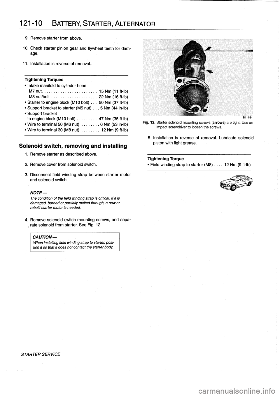
See
Fig
.
12
.
CAUTION-
When
installing
fieid
winding
strap
to
starter,
posi-
tion
it
so
that
it
does
not
contact
the
starter
body
.
STARTER
SERVICE
131~184
Fig
.
12
.
Starter
solenoid
mounting
screws
(arrows)
are
tight
.
Use
en
impact
screwdriver
to
loosen
the
screws
.
5
.
Installation
is
reverse
of
removal
.
Lubricate
solenoid
pistos
with
light
grease
.
Page 188 of 759
160-
4
FUEL
TANK
AND
FUEL
PUMP
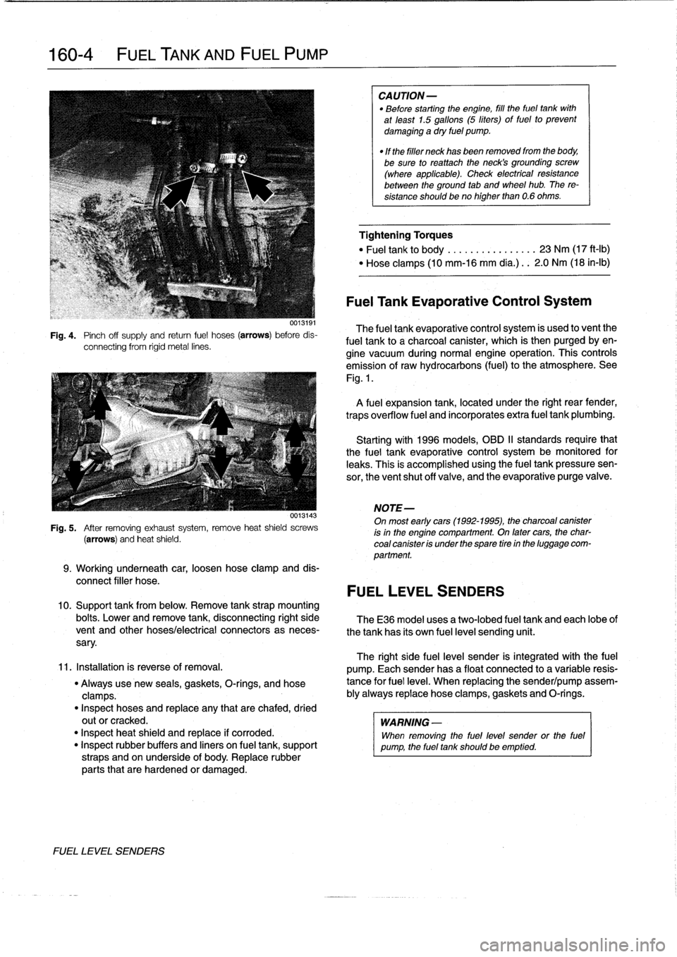
Fig
.
4
.
Pinch
off
supply
and
retum
fuel
hoses
(arrows)
before
dis-
connecting
from
rigid
metal
lines
.
0013143
Fig
.
5
.
After
removing
exhaustsystem,
remove
heat
shield
screws
(arrows)
and
heat
shield
.
9
.
Working
underneath
car,
loosen
hose
clamp
and
dis-
connect
filler
hose
.
10
.
Support
tank
from
below
.
Remove
tank
strap
mounting
bolts
.
Lower
and
remove
tank,
disconnecting
right
side
TheE36
model
uses
a
two-lobed
fuel
tank
and
each
lobeof
vent
and
other
hoses/electrical
connectors
as
neces-
the
tank
has
its
own
fuel
level
sending
unit
.
sary
.
11
.
Installation
is
reverse
of
removal
.
"
Always
use
new
seals,
gaskets,
O-rings,
and
hose
clamps
.
"
Inspect
hoses
and
replace
any
that
are
chafed,
dried
outor
cracked
.
"
Inspect
heat
shield
and
replace
if
corroded
.
"
Inspect
rubber
buffers
and
liners
on
fuel
tank,
support
straps
and
on
underside
of
body
.
Replace
rubber
parts
that
are
hardened
or
damaged
.
FUEL
LEVEL
SENDERS
CAUTION-
"
Before
starting
the
engine,
fill
the
fuel
tank
with
at
least
1.5
gallons
(5
liters)
of
fuel
to
prevent
damaging
a
dry
fuel
pump
.
"
If
the
filler
neck
has
been
removed
from
the
body,
be
sure
toreattach
theneck's
grounding
screw
(where
applicable)
.
Check
electrical
resistance
between
the
ground
tab
and
wheel
hub
.
The
re-
sistance
shouldbeno
higher
than
0
.6
ohms
.
Tightening
Torques
"
Fuel
tank
to
body
.............
...
23
Nm
(17
ft-Ib)
"
Hose
clamps
(10
mm-16
mm
día
.)
..
2
.0
Nm
(18
in-lb)
Fuel
Tank
Evaporative
Control
System
The
fuel
tank
evaporative
control
system
is
used
to
vent
the
fuel
tank
to
a
charcoal
canister,
which
is
then
purgedby
en-
gine
vacuum
during
normal
engine
operatíon
.
This
controls
emission
of
raw
hydrocarbons
(fuel)
to
the
atmosphere
.
See
Fig
.
1
.
A
fuel
expansion
tank,
located
under
the
right
rear
fender,
traps
overflow
fuel
and
incorporates
extra
fuel
tank
plumbing
.
Startingwith
1996
models,
OBD
II
standards
require
that
the
fuel
tank
evaporative
control
system
be
monitored
for
leaks
.
This
is
accomplished
usingthe
fuel
tankpressuresen-
sor,
the
ventshut
off
valve,
and
the
evaporative
purge
valve
.
NOTE-
On
most
early
cars(1992-1995),
the
charcoal
canister
is
in
the
engine
compartment
.
On
latercars,
the
char-
coal
canister
is
under
the
spare
tire
in
the
luggage
com-
partment
.
FUEL
LEVEL
SENDERS
The
right
side
fuel
leve¡
sender
is
integrated
with
the
fuel
pump
.
Each
senderhas
a
float
connected
to
a
variable
resis-
tance
for
fuel
leve¡
.
When
replacing
the
sender/pump
assem-
bly
always
replace
hose
clamps,gaskets
and
O-rings
.
WARNING
-
When
removing
the
fuel
level
sender
or
the
fuel
pump,
the
fuel
tank
should
be
emptied
.
Page 219 of 759
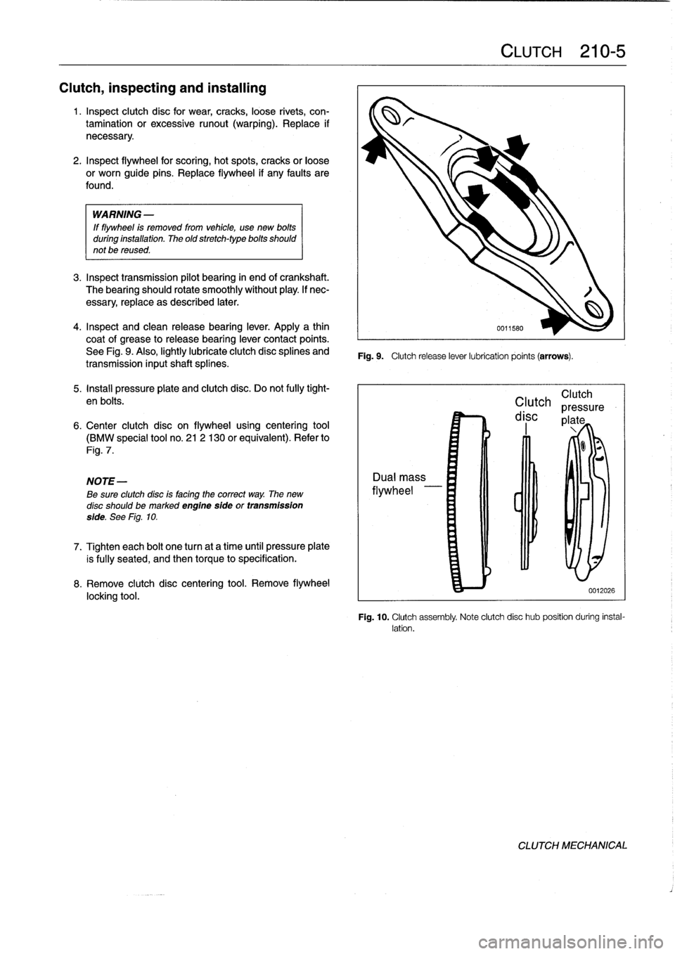
Clutch,
inspecting
and
installing
1
.
Inspect
clutch
disc
for
wear,
cracks,
loose
rivets,
con-
tamination
or
excessive
runout
(warping)
.
Replace
if
necessary
.
2
.
Inspect
flywheel
for
scoring,
hot
spots,
cracks
or
loose
or
worn
guide
pins
.
Replace
flywheel
if
any
faults
are
found
.
WARNING
-
If
flywheel
is
removed
from
vehicle,
use
new
bolts
duríng
installation
.
The
old
stretch-typebolts
should
not
be
reused
.
3
.
Inspecttransmission
pilot
bearing
in
end
of
crankshaft
.
The
bearing
should
rotate
smoothly
without
play
.
If
nec-
essary,
replace
as
described
later
.
4
.
Inspect
and
clean
releasebearing
lever
.
Apply
a
thin
coat
of
grease
to
releasebearíng
lever
contact
points
.
See
Fig
.
9
.
Also,
lightly
lubricate
clutch
disc
splines
and
transmission
inputshaft
splínes
.
5
.
Install
pressure
plate
and
clutch
disc
.
Do
not
fully
tight-
en
bolts
.
6
.
Center
clutch
disc
on
flywheel
using
centering
tool
(BMW
special
tool
no
.
21
2
130
or
equivalent)
.
Refer
to
Fig
.
7
.
NOTE-
Be
sure
clutchdísc
is
facing
the
correct
way
.
The
new
disc
should
bemarked
engine
sfde
or
transmission
side
.
See
Fig
.
10
.
7
.
Tighten
each
bolt
one
turn
at
a
time
until
pressure
plate
is
fully
seated,
and
then
torque
to
specification
.
8
.
Remove
clutch
disc
centering
tool
.
Remove
flywheel
locking
tool
.
Fig
.
9
.
Clutch
release
lever
lubrication
points
(arrows)
.
CLUTCH
210-
5
Clutch
Clutch
pressure
disc
plate
0012026
Fig
.
10
.
Clutch
assembly
Note
clutch
disc
hub
position
during
instal-
lation
.
CLUTCH
MECHANICAL
Page 220 of 759
210-
6
CLUTCH
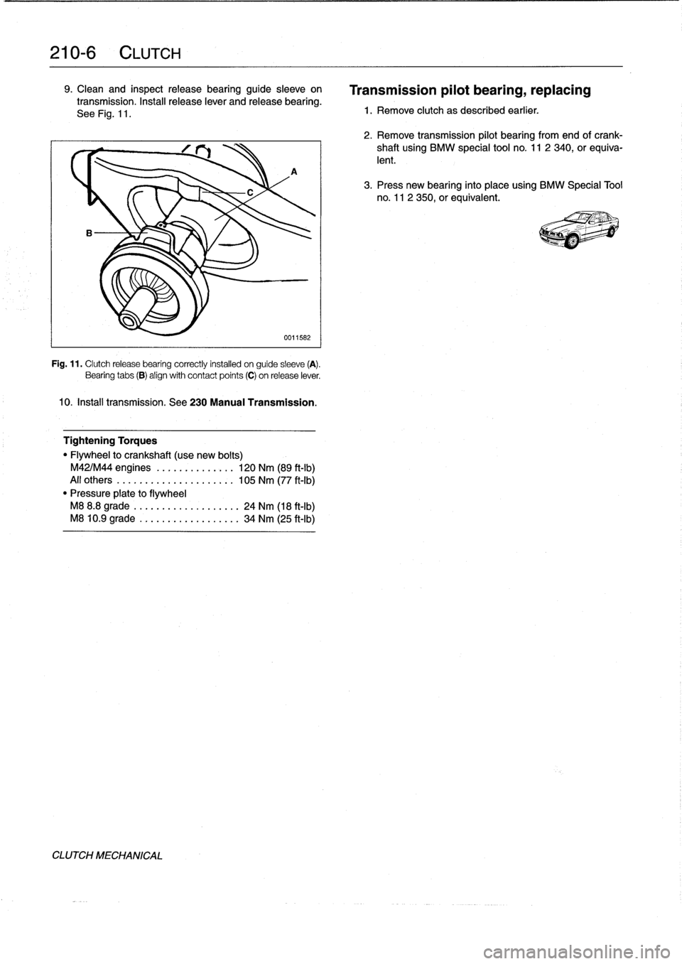
9
.
Clean
and
inspectrelease
bearing
guide
sleeve
on
transmission
.
Install
release
lever
and
release
bearing
.
See
Fig
.
11
.
A
0011582
Fig
.
11
.
Clutchrelease
bearing
correctly
installed
on
guide
sleeve
(A)
.
Bearing
tabs
(B)
align
with
contact
points
(C)
on
release
lever
.
10
.
Insta¡¡
transmission
.
See230
Manual
Transmission
.
Tightening
Torques
"
Flywheel
to
crankshaft
(use
new
bolts)
M42/M44
engines
....
.
..
...
....
120
Nm
(89
ft-Ib)
All
others
..........
..
.
..
......
105
Nm
(77
ft-Ib)
"
Pressure
píate
to
flywheel
M8
8
.8
grade
......
...
.
.
........
24
Nm
(18
ft-Ib)
M8
10
.9
grade
.....
..
..
..
.......
34
Nm
(25
ft-Ib)
CLUTCH
MECHANICAL
Transmission
pilot
bearing,
replacing
1
.
Remove
clutch
as
described
earlier
.
2
.
Remove
transmission
pilot
bearing
from
end
ofcrank-
shaft
using
BMW
special
tool
no
.
11
2
340,
or
equiva-
lent
.
3
.
Press
new
bearing
finto
placeusing
BMW
Specíal
Tool
no
.
11
2
350,or
equivalent
.