Temperature switch BMW 318i 1997 E36 Owner's Manual
[x] Cancel search | Manufacturer: BMW, Model Year: 1997, Model line: 318i, Model: BMW 318i 1997 E36Pages: 759
Page 183 of 759
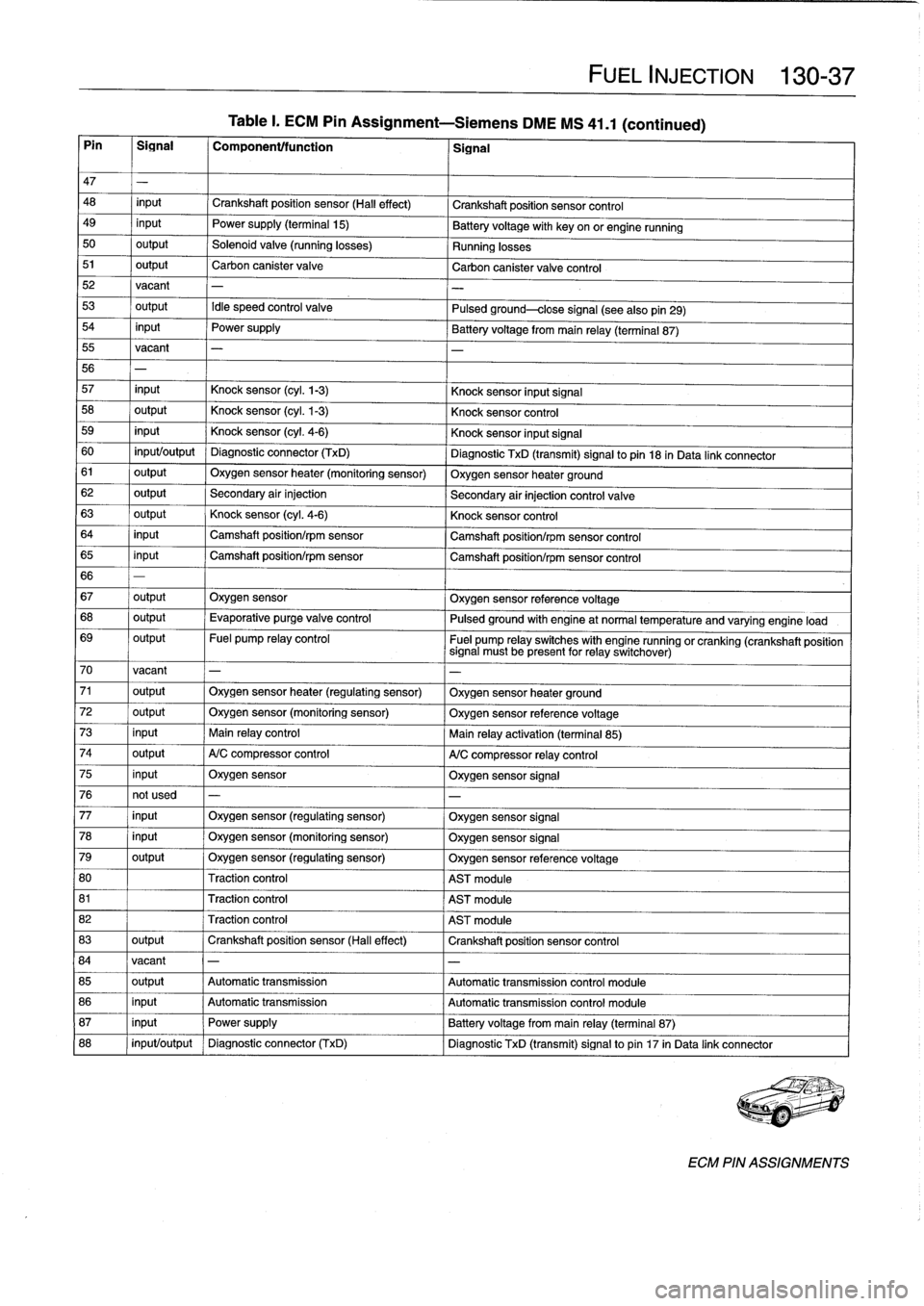
Table
I
.
ECM
Pin
Assignment-Siemens
DME
MS
41
.1
(continued)
Pin
I
Signal
I
Component/function
1
Signal
FUEL
INJECTION
130-
37
47
-
48
input
Crankshaft
position
sensor
(Hall
effect)
Crankshaft
position
sensor
control
49
input
Power
supply
(terminal
15)
Batteryvoltage
with
key
onor
engine
running
50
output
Solenoid
valve
(running
losses)
Running
losses
51
output
Carbon
canister
valve
Carbon
canister
valve
control
52vacant
-
53
output
Idle
speed
control
valve
Pulsed
ground-close
signal
(seealsopin29)
54
input
Power
supply
Battery
voltagefrom
main
relay
(terminal
87)
55
vacant
-
56
-
57
input
Knock
sensor
(cyl
.
1-3)
Knock
sensor
input
Signal
58
output
Knock
sensor
(cyl
.
1-3)
Knock
sensor
control
59
input
Knock
sensor
(cyl
.
4-6)
Knock
sensor
input
Signal
60
input/output
Diagnostic
connector
(TxD)
Diagnostic
TxD
(transmit)
signal
to
pin
18
in
Data
link
connector
61
output
Oxygen
sensor
heater
(monitoring
sensor)
Oxygen
sensor
heater
ground
62
output
Secondary
air
injection
Secondary
air
injection
control
valve
63
output
Knock
sensor
(cyl
.
4-6)
Knock
sensor
control
64
input
Camshaft
position/rpm
sensor
Camshaft
position/rpm
sensor
control
65
input
Camshaft
position/rpm
sensor
Camshaft
position/rpm
sensor
control
66
-
67
output
Oxygen
sensor
Oxygen
sensor
reference
voltage
68
output
Evaporative
purge
valve
control
Pulsed
ground
with
engine
at
normal
temperature
and
varyingengine
load
69
output
Fuel
pump
relay
control
Fuel
pump
relay
switches
with
engine
runningorcranking
(crankshaft
position
signal
must
be
present
for
relay
switchover)
70
vacant
-
-
71
output
Oxygen
sensor
heater
(regulating
sensor)
Oxygen
sensor
heater
ground
72
output
Oxygen
sensor
(monitoring
sensor)
Oxygen
sensor
referencevoltage
73
input
Main
relay
control
Main
relay
activation
(terminal
85)
74
output
A/C
compressor
control
A/C
compressor
relay
control
75
input
Oxygen
sensor
Oxygen
sensor
signal
76
not
used
-
-
77
input
Oxygen
sensor
(regulating
sensor)
Oxygen
sensor
signal
78
input
Oxygen
sensor
(monitoring
sensor)
Oxygen
sensor
signal
79
output
Oxygen
sensor
(regulating
sensor)
Oxygen
sensor
referencevoltage
80
Traction
control
AST
module
81
Traction
control
AST
module
82
Traction
control
AST
module
83
output
Crankshaft
position
sensor
(Hall
effect)
Crankshaft
position
sensor
control
84
vacant
-
-
85
output
Automatic
transmission
Automatic
transmission
control
module
86
input
Automatic
transmission
Automatic
transmissíon
control
module
87
input
Power
supply
Battery
voltage
from
main
relay
(terminal
87)
88
input/output
Diagnostic
connector
(TxD)
Diagnostic
TxD
(transmit)
signal
to
pin
17
in
Data
link
connector
ECM
PIN
ASSIGNMENTS
Page 195 of 759
170
Radiator
and
Cooling
System
GENERAL
.
.
.....
.
...
.
.
.
.
.
....
.
.
.
.
.
.
.
.170-1
Coolant
Pump
and
Thermostat
........
.
.
.
.
170-1
Radiator
and
Expansion
Tank
.........
.
...
170-1
Cooling
Fans
.
....
.
.
.
.
.
.
.
.
.
.....
.
......
170-2
Warnings
and
Cautions
.
.
.
.
.
.
.
.
.
.
.
.
...
.
.
.
170-2
TROUBLESHOOTING
...
.
.
.
...
.
.
.
.
.
.
.
.
.170-2
Cooling
System
Pressure
Test
...
.
.
.
.
.
.
.
.
.
170-3
Thermostat
Quick
Check
.
.
.
.
...
.
.
.
.
.
.
.
.
.
170-3
Temperature
Gauge
Quick
Check
.
.
.
.
.
.
.
.
.
170-3
Cooling
fan,
testing
.
.
.
.
........
.
.
.
.
.
.
.
.
.
170-4
COOLING
SYSTEM
SERVICE
.
.
.
.
.
.
.
.
.
.
170-5
Coolant,draining
and
filling
.
.
......
.
.
.
.
.
..
170-5
Cooling
system,
bleeding
(radiator
with
integral
expansion
tank)
.....
170-6
GENERAL
This
section
covers
repair
and
troubleshooting
information
for
the
engine
cooling
system
.
For
heater
core
and
related
heating
and
air
conditioning
components,
see640
Heating
and
Air
Conditioning
.
Coolant
Pump
and
Thermostat
A
centrifuga¡-type
coolant
pump
is
mounted
to
the
front
of
the
engíne
.
The
belt-driven
pump
circulates
coolant
through
the
system
whenever
the
engíne
is
running
.
A
thermostat
con-
trols
the
flow
of
coolant
into
the
radiator
.
When
the
engíne
is
cold
the
thermostat
is
closed
so
coolant
bypasses
the
radiator,
recirculating
from
the
engíne
directly
back
to
the
pump
.
When
the
engíne
reaches
operating
tem-
perature,
the
thermostat
opens
and
coolant
circulates
through
the
whole
system
including
the
radiator
.
Radiator
and
Expansion
Tank
The
radiator
is
a
crossflow
design
.
A
translucent
expansion
tank
provides
for
coolant
expansion
at
higher
temperatures
and
easy
monitoringof
the
coolant
leve¡
.
On
4-cylinder
modeis,
the
radiator
expansion
tank
is
integral
with
the
radiator
.
See
Fig
.
1
.
RADIATOR
AND
COOLING
SYSTEM
170-1
Belt-driven
cooling
fan,
replacing
.
.......
.
.
.
170-7
Electric
cooling
fan,
replacing
.
.
.
.....
.
.
.
.
.
170-8
Auxiliary
cooling
fan,
replacing
.
.
.....
.
.
.
.
.
170-8
Thermostat,
replacing
.
.
.
.
.
.
.
.
.
.....
.
.
.
.
.
170-9
Coolant
pump,
replacing
..........
.
.
.
.
.
.
170-10
RADIATOR
SERVICE
.....
.
......
.
.
.
.
.
.
170-11
Radiator,
removing
and
installing
....
.
.
.
.
.
.
170-11
TABLES
a
.
Coolant
Temperature
Sensor
Wire
Colors
...
.
..
.
.
170-3b
.
Auxiliary
Cooling
Fan
Switching
Temperatures
.:.
.170-4
c
.
Auxiliary
Cooling
Fan
Temperature
Switch
Tests
..
..
.
...
...
.
.............
.
..
.
.
170-5d
.
Cooling
System
Capacities
..............
..
.
.
.
170-6
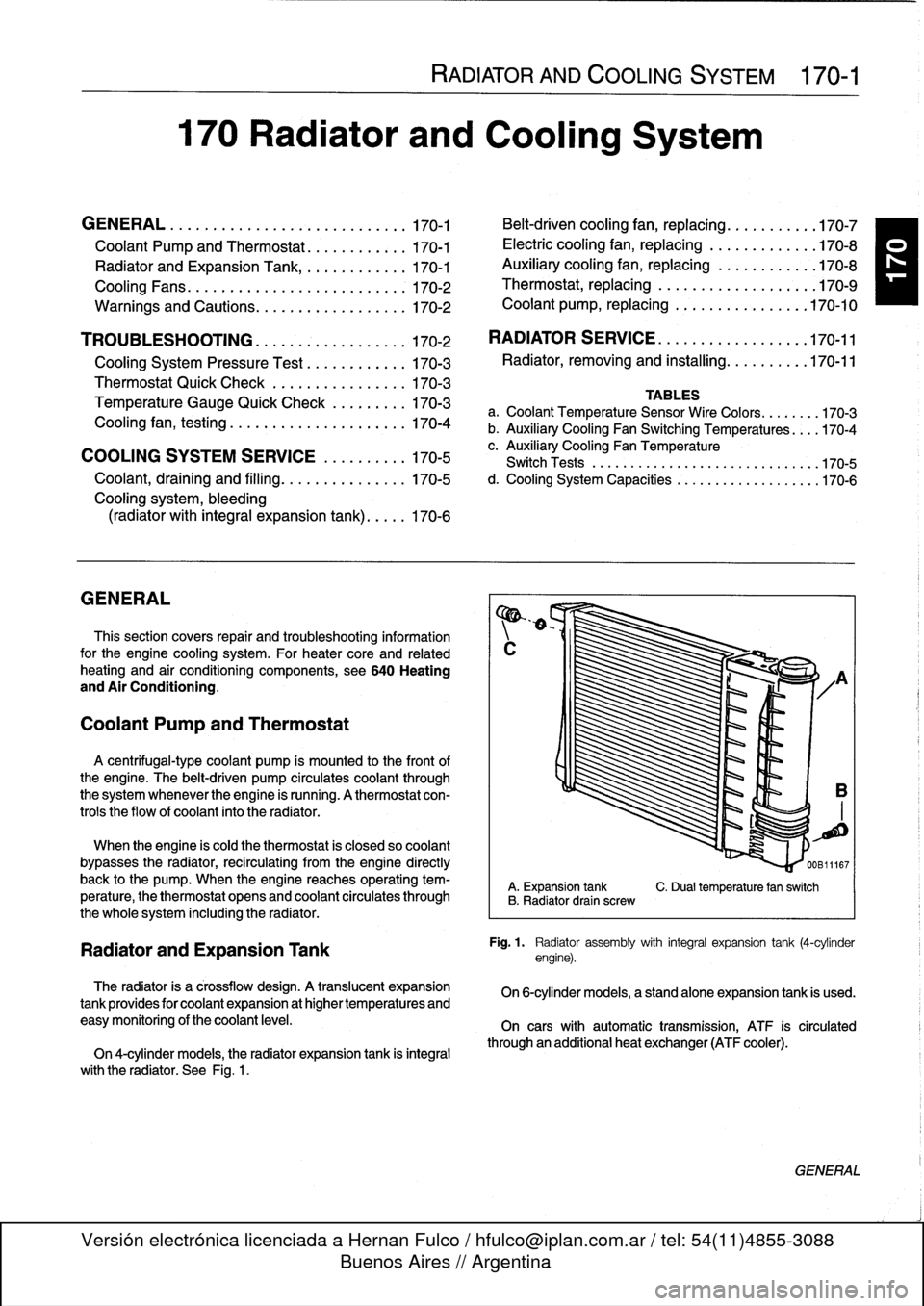
A
.
Expansion
tank
C
.
Dualtemperature
fan
switch
B
.
Radiator
drain
screw
Fig
.
1
.
Radiator
assembly
with
integral
expansion
tank
(4-cylinder
engine)
.
On
6-cylinder
models,
a
standalone
expansion
tank
is
used
.
On
cars
with
automatic
transmission,
ATF
is
circulated
through
an
additional
heat
exchanger
(ATF
cooler)
.
GENERAL
Page 198 of 759
170-
4
RADIATOR
AND
COOLING
SYSTEM
A
quick
testat
the
coolant
temperature
gauge
sender
can
The
auxiliary
cooling
fan
comes
on
when
coolant
tempera
determine
if
the
gauge
is
functioning
correctly
.
ture
exceeds
a
predetermined
leve¡
or
whenever
the
air
condi-
tioning
is
on
.
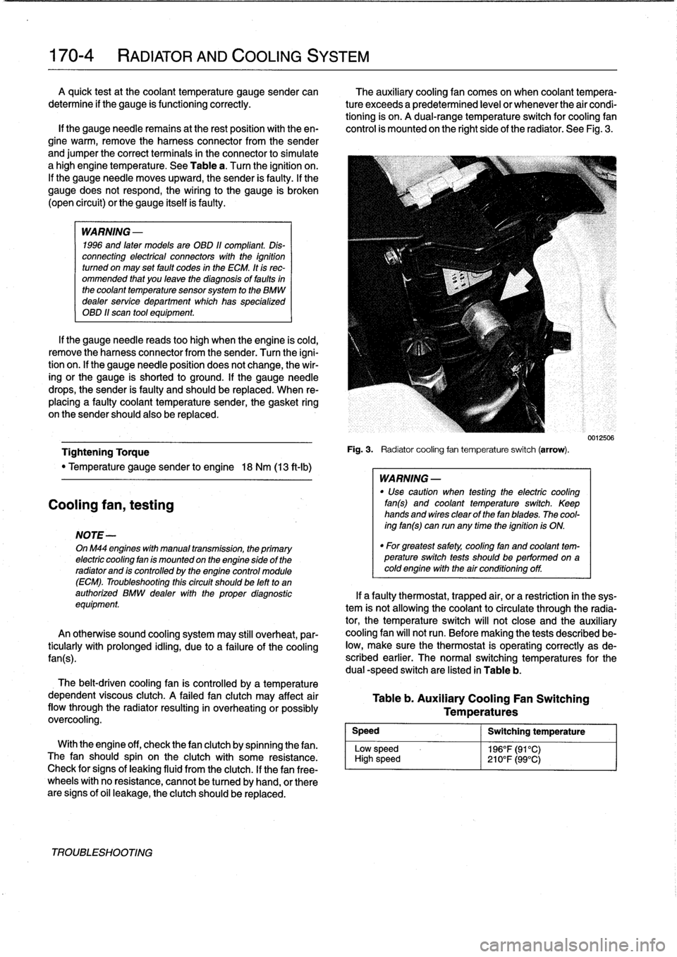
A
dual-range
temperature
switch
for
cooling
fan
lf
the
gauge
needie
remains
at
the
rest
position
with
theen-
control
is
mounted
on
the
right
side
of
the
radiator
.
See
Fig
.
3
.
gine
warm,
remove
the
harness
connector
from
the
sender
and
jumper
the
correct
terminals
in
the
connector
to
simulate
a
high
engine
temperature
.
See
Table
a
.
Turn
the
ignition
on
.
If
the
gauge
needle
moves
upward,
the
sender
is
faulty
.
If
the
gauge
does
not
respond,
the
wiring
to
the
gauge
is
broken
(open
circuit)
or
the
gauge
itselfis
faulty
.
WARNING
-
1996
and
laten
models
are
OBD
11
compliant
.
Dis-
connecting
electrical
connectors
wíth
the
ignition
turned
on
may
set
fault
codes
in
the
ECM
.
It
is
rec-
ommended
that
you
leave
the
diagnosis
of
faults
in
the
coolant
temperature
sensorsystem
to
the
BMW
dealer
service
department
which
has
specialized
OBD
11
scan
tool
equipment
.
If
the
gauge
needle
reads
too
high
when
the
engine
is
cold,
remove
the
harness
connector
from
the
sender
.
Turn
the
igni-
tion
on
.
lf
the
gauge
needle
position
does
not
change,
the
wir-
ing
or
the
gauge
is
shorted
to
ground
.
If
the
gauge
needle
drops,
the
sender
is
faulty
and
should
be
replaced
.
When
re-
placing
a
faulty
coolant
temperature
sender,
the
gasket
ring
on
the
sender
should
also
be
replaced
.
Tightening
Torque
"
Temperature
gauge
sender
to
engine
18
Nm
(13
ft-Ib)
Cooling
fan,
testing
NOTE-
OnM44
engines
with
manual
transmission,
the
primary
electric
cooling
fan
is
mounted
on
the
engine
side
of
the
radiator
and
is
controlled
by
the
engine
control
module
(ECM)
.
Troubleshooting
thiscircuit
should
be
left
to
an
authorized
BMW
dealer
with
the
proper
diagnostic
equipment
An
otherwise
sound
cooling
system
may
still
overheat,
par-
ticularly
with
prolonged
idling,
due
to
a
failure
of
the
coolíng
fan(s)
.
The
belt-driven
cooling
fan
is
controlled
by
a
temperature
dependent
viscous
clutch
.
A
failed
fan
clutch
may
affect
air
flow
through
the
radiator
resulting
in
overheating
orpossibly
overcooling
.
Speed
Low
sp
High
s
With
the
engine
off,
check
thefan
clutch
by
spinning
thefan
.
eed
The
fan
should
spin
on
the
clutch
with
some
resistance
.
peed
Check
for
signs
of
leaking
fluid
from
the
clutch
.
If
thefan
free-
wheels
with
no
resistance,
cannot
be
tu
rned
by
hand,
or
there
are
signs
of
oil
leakage,
the
clutch
should
be
replaced
.
TROUBLESHOOTING
Fig
.
3
.
Radiatorcooling
fan
temperature
switch
(arrow)
.
WARNING
-
"
Use
caution
when
testing
the
electric
cooling
fan(s)
and
coolant
temperature
switch
.
Keep
hands
and
wires
clear
of
thefan
blades
.
The
cool-
ing
fan(s)
can
run
any
time
the
ignition
is
ON
.
"
For
greatest
safety,
coolíng
fan
and
coolant
tem-perature
switch
tests
shouldbe
performed
on
acoldengine
with
the
air
conditioning
off
.
Table
b
.
Auxiliary
Cooling
Fan
Switching
Temperatures
Switching
temperature
196°F(91°C)
210°F(99°C)
0012506
If
a
faulty
thermostat,
trapped
air,
or
a
restriction
in
the
sys-
tem
is
not
allowing
the
coolant
to
circulate
through
the
radia-
tor,
the
temperature
switch
will
not
close
and
the
auxiliary
cooling
fan
will
not
run
.
Before
making
the
tests
described
be-
low,
make
sure
the
thermostat
is
operating
correctly
as
de-
scribed
earlier
.
The
normal
switching
temperatures
for
the
dual
-speed
switch
are
listed
in
Table
b
.
Page 199 of 759
NOTE-
Some
cars
covered
by
this
manual
may
have
an
alter-
nate
cooling
fan
switchwith
switching
temperatures
of
176%190W
(80%88°C)
.
When
replacing
the
switch
check
theswitching
specifications,
whichshouldbe
stamped
on
the
switch
body
.
1
.
If
coolant
is
circulating
at
normal
operating
tempera-
ture,
but
auxiliary
cooling
fan
does
not
run,
disconnect
connector
from
radiator
temperature
switch
and
make
tests
listed
in
Table
c
.
Table
c
.
Auxiliary
Cooling
Fan
Temperature
Switch
Tests
Wires
jumpered
Test
Test
resuits
conditions
Black/green
(terminal2)
and
Ignition
ON
Fan
runs
on
brown
(terminal
1)
low
speed
Black/gray
(terminal
3)
and
Ignition
ON
Fan
runson
brown
(terminal
I
1)
high
speed
2
.
If
fan
runs
only
when
powered
directly
by
jumpered
connector
and
hot
coolant
is
circulating
through
radia-
tor,
radiator
temperature
switch
is
most
likelyfaulty
.
Use
a
new
sealing
ring
when
replacing
switch
Tightening
Torque
"
Temperature
switch
to
radiator
......
15
Nm
(11
ft-Ib)
3
.
If
auxiliary
fan
does
notrun
when
powered
directly,
check
for
battery
voltage
at
temperature
switch
connec-
tor
(black/green
wire)
with
ignition
on
.
If
battery
voltage
is
not
present,
check
fuses
.
See
610
Electrical
Com-
ponent
Locations
.
RADIATOR
AND
COOLING
SYSTEM
170-
5
~r~nmm
a
00
0
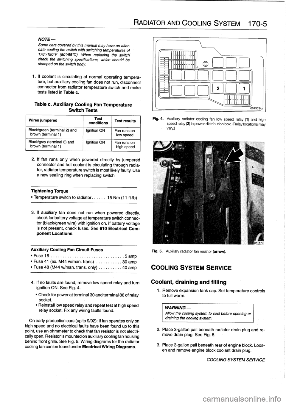
Fig
.
4
.
Auxiliary
radiator
cooling
fan
low
speed
relay
(1)
and
high
speed
relay
(2)
in
power
distribution
box
.
(Relay
locations
may
vary
.)
Auxiliary
Cooling
Fan
Circuit
Fuses
Fig
.
5
.
Auxiliary
radiator
fan
resistor
(arrow)
.
"
Fuse16
.
...................
..
..
...
...
.5
amp
"
Fuse
41
(ex
.
M44
w/man
.
trans)
.
..
.
..
.....
30
amp
"
Fuse
48
(M44
w/man
.
trans
.
only)
..
.
..
.....
40
amp
COOLING
SYSTEM
SERVICE
0013034
4
.
If
no
faults
are
found,
remove
low
speed
relay
and
turn
Coolant,draining
and
filling
ignition
ON
.
See
Fig
.
4
.
1
.
Remove
expansion
tank
cap
.
Set
temperature
controls
"
Check
for
power
at
terminal
30
and
terminal
86
of
relay
to
full
warm
.
socket
.
"
Reinstall
low
speed
relay
and
repeat
testat
high
speed
WARNING
-
relay
socket
.
Fix
any
wiring
faults
found
.
Allow
the
cooling
system
to
cool
before
openlng
or
On
early
productioncars
(up
to
9/92)
:
If
fan
operates
only
on
draining
the
cooling
system
.
high
speed
and
no
electrical
faults
have
been
foundup
to
this
point,
usean
ohmmeter
to
check
that
fan
resistor
is
not
electri-
2
.
Place
3
ra
allo
ug
.
beneath
radiator
drain
plug
and
re-
cally
open
.
Resistor
is
mounted
on
auxiliary
cooling
fan
housing
move
drain
plg
.
See
Fig
.
6
.
behind
front
grille
.
See
Fig
.
5
.
Wiring
diagrams
for
the
radiator
cooling
fan
canbefoundunder
Electrical
Wiring
Diagrams
.
3
.
Place
3-g
pail
beneath
rear
of
engine
blo
.
Loos-
en
and
re
mlon
ove
engine
blockcoolant
drain
plug
k
.
COOLING
SYSTEM
SERVICE
Page 205 of 759
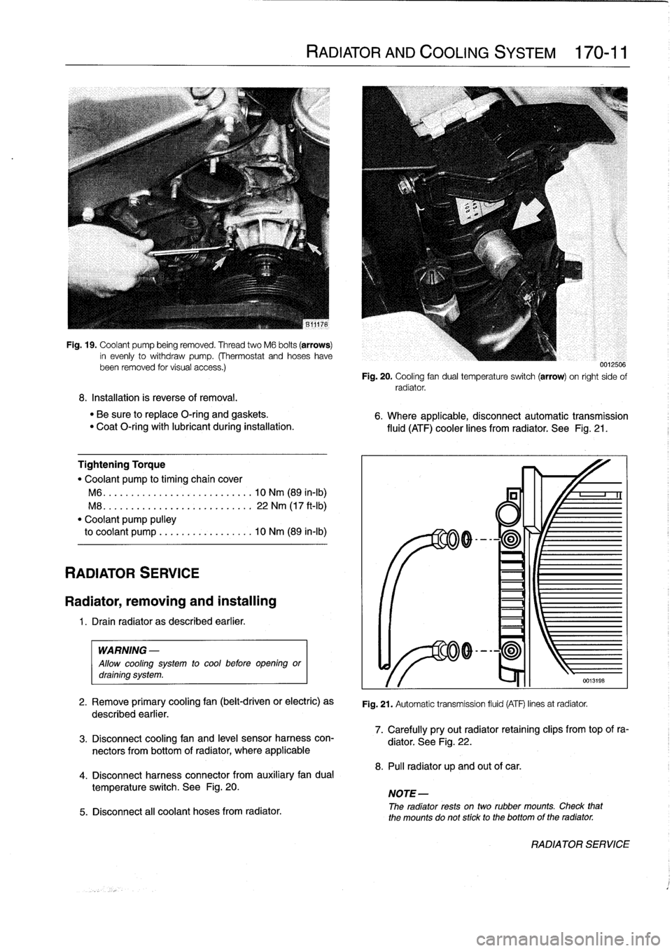
Fig
.
19
.
Coolant
pump
being
removed
.
Thread
two
M6
bolts
(arrows)
in
evenly
to
withdraw
pump
.
(Thermostat
and
hoseshavebeen
removed
tor
visual
access
.)
8
.
Installation
is
reverse
of
removal
.
"
Be
sure
to
replace
O-ring
and
gaskets
.
"
Coat
O-ring
with
lubricant
during
installation
.
Tightening
Torque
"
Coolant
pump
to
timing
chaincover
M6
...
.
...................
..
.
.
10
Nm
(89
in-lb)
M8
.
..
.
....................
.
.
.
22
Nm
(17
ft-Ib)
"
Coolant
pump
pulley
to
coolant
pump
.................
10
Nm
(89
in-lb)
RADIATOR
SERVICE
Radiator,
removing
and
installing
1
.
Drain
radiator
as
described
earlier
.
WARNING
-
Allow
cooling
system
to
cool
before
opening
ordraining
system
.
2
.
Remove
primary
cooling
fan
(belt-driven
or
electric)
as
described
earlier
.
3
.
Disconnect
coolingfan
and
leve¡
sensor
harness
con-
nectors
from
bottom
of
radiator,
where
applicable
4
.
Disconnect
harness
connector
from
auxiliary
fandual
temperature
switch
.
See
Fig
.
20
.
5
.
Disconnect
all
coolant
hoses
from
radiator
.
RADIATOR
AND
COOLING
SYSTEM
170-11
0012500
Fig
.
20
.
Cooling
fan
dual
temperatura
switch
(arrow)
on
right
sido
of
radiator
.
6
.
Where
applicable,
disconnectautomatic
transmission
fluid
(ATF)
cooler
lines
from
radiator
.
See
Fig
.
21
.
Fig
.
21
.
Automatic
transmission
fluid
(ATF)
linos
at
radiator
.
7
.
Carefully
pryout
radiator
retaining
clips
from
top
of
ra-
diator
.
See
Fig
.
22
.
8
.
Pul¡
radiator
up
and
out
of
car
.
NOTE-
The
radiator
rests
ontwo
rubber
mounts
.
Check
that
the
mounts
do
not
stick
to
the
bottomof
the
radiator
.
RADIATOR
SERVICE
Page 307 of 759
Ambient
temperaturelclock
MÍM
Aa
.Mi}rm
-Mil"
IMua~naa~u~itacar
"
za
.~
Central
Body
Electronics
0013028
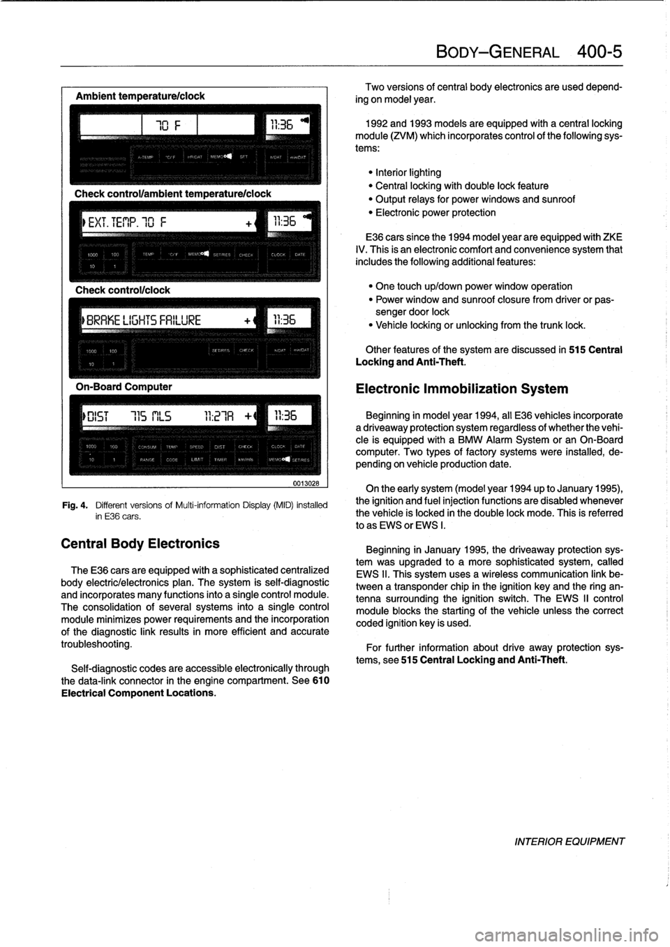
Fig
.
4
.
Different
versionsof
Multi-information
Display(MID)
installed
in
E36
cars
.
The
E36
cars
are
equipped
with
a
sophisticated
centralized
body
electric/electronics
plan
.
The
system
is
self-diagnostic
and
incorporates
many
functions
into
a
single
control
module
.
The
consolidation
of
several
systems
into
a
single
control
module
minimizes
power
requirements
and
the
incorporation
of
the
diagnostic
link
results
in
more
efficient
and
accurate
troubleshooting
.
Self-diagnostic
codes
are
accessible
electronically
through
the
data-link
connector
in
the
engine
compartment
.
See610
Electrical
Component
Locations
.
BODY-GENERAL
400-
5
Two
versions
of
central
body
electronics
are
used
depend-
ing
on
model
year
.
1992
and
1993
models
are
equipped
with
a
central
locking
module
(ZVM)
which
incorporates
control
of
the
following
sys-
tems
:
"Interiorlighting
"
Central
locking
with
double
lock
feature
"
Output
relays
for
powerwindows
and
sunroof
"
Electronic
power
protection
E36
cars
since
the
1994
model
year
are
equipped
with
ZKE
IV
.
This
is
an
electronic
comfort
and
convenience
system
that
includes
the
following
additional
features
:
"
One
touch
up/down
power
window
operation
"
Power
window
and
sunroof
closure
from
driver
or
pas-
sengerdoor
lock
"
Vehicle
locking
or
unlocking
from
the
trunk
lock
.
Other
features
of
the
system
are
discussed
in
515
Central
Locking
and
Anti-Theft
.
Electronic
Immobilization
System
Beginning
in
model
year
1994,
all
E36
vehicles
incorporate
adriveaway
protection
system
regardless
of
whether
the
vehi-
cle
is
equipped
with
a
BMW
Alarm
System
or
an
On-Board
computer
.
Two
types
of
factory
systems
were
installed,
de-
pending
on
vehicle
production
date
.
On
the
early
system
(model
year
1994
up
to
January
1995),
the
ignition
and
fuel
injection
functions
are
disabled
whenever
the
vehicle
is
locked
in
the
double
lock
mode
.
This
is
referred
lo
as
EWS
or
EWS
I
.
Beginning
in
January
1995,
the
driveaway
protection
sys-
tem
was
upgraded
to
a
more
sophisticated
system,
called
EWS
II
.
This
system
uses
a
wireless
communication
link
be-
tween
a
transponder
chip
in
the
ignition
keyand
the
ring
an-
tenna
surrounding
the
ignition
switch
.
The
EWS
II
control
module
blocksthe
starting
of
the
vehicle
unlessthe
correct
coded
ignition
key
is
used
.
For
further
information
about
drive
away
protection
sys-
tems,
see
515
Central
Locking
and
Anti-Theft
.
INTERIOR
EQUIPMENT
Page 326 of 759
510-4
EXTERIOR
TRIM,
BUMPERS
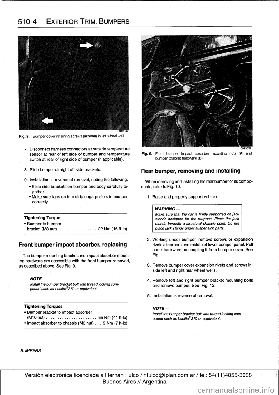
Fig
.
8
.
Bumper
cover
retaining
screws
(arrows)
in
left
wheel
weil
.
7
.
Disconnect
harnessconnectors
at
outside
temperature
0013052
sensor
at
rear
of
left
side
of
bumperand
temperatura
Fig
.
9
.
Front
bumper
impact
absorber
mounting
nuts
(A)
and
switch
at
rear
of
right
side
of
bumper
(if
applicable)
.
bumper
bracket
hardware
(B)
.
8
.
Slide
bumper
straight
off
sida
brackets
.
9
.
Installation
is
reverse
of
removal,
notingthe
following
:
When
removing
and
installing
therear
bumper
or
its
compo-
"
Slide
side
brackets
on
bumper
and
body
carefully
to-
nents,
referto
Fig
.
10
.
gether
.
"
Make
sure
tabs
on
trim
strip
engage
slots
in
bumper
1
.
Raise
and
properly
support
vehicle
.
correctly
.
Tightening
Torque
"
Bumper
to
bumper
bracket
(M8
nut)
............
...
.
.
22
Nm
(16
ft-Ib)
2
.
Working
under
bumper,
remove
screws
or
expansion
Front
bumper
impact
absorber,replacing
rivetsat
corners
and
middle
of
lower
bumper
panel
.
Pull
panel
backward,
uncoupling
it
from
bumper
cover
.
See
Thebumper
mounting
bracket
and
impact
absorber
mount-
Fig
.
11
.
ing
hardware
are
accessible
with
the
Font
bumper
removed,
as
described
above
.
See
Fig
.
9
.
3
.
Remove
bumper
cover
expansion
rivets
and
screws
in-
side
left
and
right
rear
wheel
wells
.
NOTE
-
Install
the
bumper
bracket
boltwith
thread
locking
com-
pound
suchas
Loctite
8
270
or
equivalent
.
Tightening
Torques
"
Bumper
bracket
to
impact
absorber
(M10
nut)
.
..
.
...
.............:.
55
Nm
(41
ft-Ib)
"
Impact
absorber
to
chassis
(M6
nut)
...
9
Nm
(7
ft-Ib)
BUMPERS
Rear
bumper,
removing
and
installing
WARNING
-
Make
sure
that
the
car
is
firmly
supported
on
jack
stands
designad
for
the
purpose
.
Place
the
jack
stands
beneath
a
structural
chassis
point
.
Do
not
place
jack
stands
under
suspension
parts
.
4
.
Remove
left
and
right
bumper
bracket
mounting
bolts
and
remove
bumper
.
See
Fig
.
12
.
5
.
Installation
is
reverse
of
removal
.
NOTE-
Install
the
bumper
bracket
bolt
with
thread
locking
com-
pound
suchas
Loctite®270
or
equivalent
.
Page 382 of 759
600-2
ELECTRICAL
SYSTEM-GENERAL
CAUTION
-
"
Always
turn
off
the
engine
and
disconnect
the
negative
()
cable
from
the
batterybefore
remov-
ing
any
electrical
components
.
Disconnecting
the
battery
may
erase
fault
code(s)
stored
in
control
module
memory
.
Check
for
fault
codes
using
spe-
cial
BMW
diagnostic
equipment
.
"
Prior
to
disconnecting
the
battery,
read
the
bat-
tery
disconnection
cautions
given
at
the
front
of
this
manual
onpage
viii
.
"
Connect
and
disconnect
ignition
system
wires,
multiple
connectors,
and
ignition
test
equipment
leads
only
while
the
ignition
is
off
.
"
Do
not
disconnect
the
battery
with
engine
run-
ning
.
"
Do
not
quick-charge
the
battery
(for
boost
start-
ing)
for
longer
than
one
minute,
and
do
not
ex-
ceed
16
.5
volts
at
the
battery
with
the
boosting
cables
attached
.
Wait
at
feast
one
minute
before
boosting
the
battery
a
second
time
.
"
Do
not
usea
test
famp
that
has
a
normal
incan-
descent
bulb
to
test
circuits
contafning
electronic
components
.
The
high
electrical
consumptionof
these
test
lamps
may
damage
the
components
.
"
Do
not
use
an
analog
meter
.
Use
onfy
a
digital
multimeter
.
"
Many
of
the
solid-state
modules
are
static
sensi-
tive
.
Static
discharge
will
permanently
damage
them
.
Always
handle
the
modules
using
proper
static
prevention
equipment
and
techniques
.
"
To
avoid
damaging
harness
connectors
or
relay
panel
sockets,
use
jumper
wires
with
flat-blade
connectors
that
are
the
same
size
as
the
connec-
tor
or
relay
terminals
.
"
Always
switch
a
digital
multimeter
to
the
appropri-
ate
function
and
range
before
making
test
con-
nections
.
"
Do
not
tryto
start
the
engine
of
a
carwhich
has
been
heated
above176°F
(80°C),
(for
example,
in
a
paint
dryingbooth)
.
Allow
it
to
cool
to
normal
temperature
.
"
Disconnect
the
battery
before
dolng
any
electric
welding
on
the
car
.
"
Do
not
wash
the
engine
while
it
is
runnfng,
or
any-
time
the
ignition
is
switched
on
.
WIRING
DIAGRAMS
Electrical
Test
Equipment
Many
of
the
electrical
tests
described
in
this
manual
call
for
measuring
voltage,
currentorresistanceusing
a
digital
multi-
meter
(DMM)
.
Digital
meters
are
preferred
for
precise
mea-
surements
and
for
electronics
work
because
they
are
generally
more
accuratethan
analog
meters
.
The
numerical
display
is
alsoless
likely
to
be
misread,
since
there
is
no
nee-
dle
position
to
be
misinterpreted
by
reading
at
an
angle
.
An
LED
test
light
is
a
safe,
inexpensive
tool
that
can
be
used
to
perform
many
simple
electrical
tests
that
would
otherwise
require
a
digital
multimeter
.
The
LED
indicates
when
voltage
is
present
between
anytwo
test-points
in
a
circuit
.
CA
UTION-
"
Choose
test
equipment
carefully
.
Use
a
digital
multimeter
with
at
leadt
10
megaohm
input
im-
pedance,or
an
LED
test
light
.
An
analog
meter
(swing-need1e)
ora
test
light
with
a
normal
incan-
descent
bulb
may
draw
enough
current
to
dam-
age
sensitive
electronic
components
.
"
An
ohmmeter
must
not
beused
to
measure
resis-
tance
on
solidstate
components
suchas
controlunits
or
time
delay
relays
.
"
Always
disconnect
the
battery
before
making
re-
sístance
(ohm)
measurements
on
the
circuit
.
WIRING
DIAGRAMS
The
wiring
diagrams
shown
in
Electrical
Wiring
Diagrams
have
been
specially
designed
to
enable
quick
and
efficientdi-
agnosis
and
troubleshooting
of
electrical
malfunctions
.
Wiring
Codes
and
Abbreviations
A
lot
of
information
is
included
in
each
wiring
diagram
if
you
know
how
to
read
them
.
Wire
colors
in
the
diagrams
are
ab-
breviated
.
Combined
color
codes
indicate
a
multi-colored
wire
.
For
example
the
code
BLU/RED
indicates
a
Blue
wire
with
a
Red
stripe
.
Many
electrical
components,
connectors,
fuses,
and
ground
locations
are
identified
using
a
unique
number
.
Each
of
there
numbers
corresponds
to
a
particular
part
in
the
circuit
commonly
found
in
Electrical
Wiring
Diagrams
.
Page 396 of 759
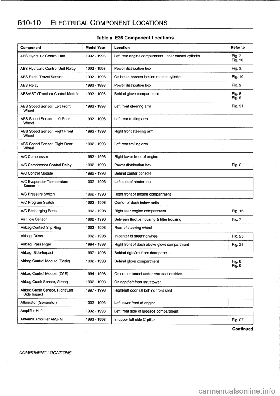
610-10
ELECTRICAL
COMPONENT
LOCATIONS
Component
Model
Year
Location
Refer
to
ABS
Hydraulic
Control
Unit
1992-1998
Left
rear
engine
compartment
undermaster
cylinder
Fig
.
7
.
Fig
.
10
.
ABS
Hydraulic
Control
Unit
Relay
1992-1998
Power
distribution
box
Fig
.
2
.
ABS
Pedal
Travel
Sensor
1992-1998
On
brake
booster
beside
master
cylinder
Fig
.
10
.
ABS
Relay
1992-1998
Power
distribution
box
Fig
.
2
.
ABS/AS
T
(Traction)
Control
Module
1992-1998
Behind
glove
compartment
Fig
.
8
.
Fig
.
9
.
ABS
Speed
Sensor,
Left
Front
1992-1998
Left
front
steering
arm
Fig
.
31
.
Wheel
ABS
Speed
Sensor,
Left
Rear
1992-1998
Left
rear
trailing
arm
Wheel
ABS
Speed
Sensor,
RightFront
11992-1998
Right
front
steering
arm
Wheel
ABS
Speed
Sensor,
Right
Rear
1992-1998
I
Left
rear
trailing
arm
Wheel
1
A/C
Compressor
1
1992-1998
(
Rightlower
frontof
engine
A/C
Compressor
Control
Relay
1
1992-1998
1992-1998
1992-1998
A/C
Control
Module
A/C
Evaporator
Temperature
Sensor
A/C
Pressure
Switch
1992-1998
Right
frontof
engine
compartment
A/C
Program
Switch
1992-1998
Center
of
dash
below
radio
A/CRecharging
Ports
1992-1998
Right
rear
engine
compartment
Fig
.
16
.
Air
Flow
Sensor
1992-1998
Between
throttle
housing
&
filter
housing
Fig
.
7
.
Airbag
Contact
Slip
Ring
1992-1998
Rear
ofsteering
wheel
Airbag,
Driver
1992-1998
In
center
of
steering
wheel
Fig
.
25
.
Airbag,
Passenger
1994-1998
Right
front
of
dash
above
glove
compartment
Fig
.
26
.
Airbag,
Side-Impact
1997-1998
Behind
right/left
front
door
panel
Airbag
Control
Module
(Basic)
1992-1993
Behind
glove
compartment
Fig
.
8
.
Fig
.
9
.
Airbag
Control
Module
(ZAE)
1994-1998
On
center
tunnel
under
rear
seat
cushion
Airbag
Crash
Sensor,
Airbag
1992-1993
On
righUleft
front
strut
tower
Airbag
Crash
Sensor,
Right/Left
1997-1998
Right/left
door
si¡¡
behind
front
seatSide
Impact
Alternator
(Generator)
1992-1998
Left
lowerfront
of
engine
Amplifier
Hi-fi
1992-1998
Left
front
side
of
luggage
compartment
Antenna
Amplifier
AM/FM
1992-1998
In
upper
left
side
C-pillar
Fig
.
27
.
COMPONENT
LOCA
TIONS
Table
a
.
E36
Component
Locations
Power
distribution
box
Fig
.
2
.
Behind
center
console
Left
sideof
heater
box
Continued
Page 398 of 759
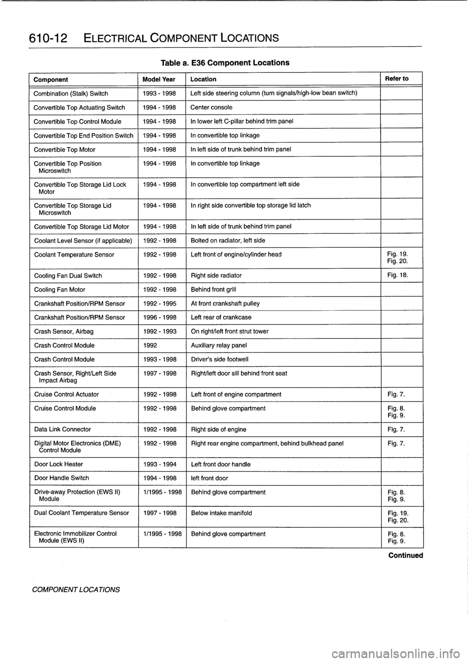
610-12
ELECTRICAL
COMPONENT
LOCATIONS
Table
a
.
E36
Component
Locations
Component
Model
Year
Location
Refer
to
Combination
(Stalk)
Switch
1993-1998
Left
sidesteering
column
(turn
signals/high-low
bean
switch)
Convertible
Top
ActuatingSwitch
1994-1998
Center
console
Convertible
Top
Control
Module
1994-1998
In
lower
left
C-pillar
behind
trim
panel
Convertible
TopEnd
Position
Switch
1994-1998
In
convertible
top
linkage
Convertible
Top
Motor
1994-1998
In
left
sideof
trunk
behind
trim
panel
Convertible
Top
Position
1994-1998
In
convertible
top
linkage
Microswitch
Convertible
Top
Storage
Lid
Lock
1994-1998
In
convertible
top
compartment
left
side
Motor
Convertible
Top
Storage
Lid
1994-1998
Inright
side
convertible
top
storage
lid
latch
Microswitch
Convertible
Top
Storage
Lid
Motor
1994-1998
In
left
side
of
trunk
behind
trim
panel
Coolant
Leve¡
Sensor
(if
applicable)
1992-1998
Bolted
on
radiator,
left
side
Coolant
Temperature
Sensor
1992-1998
Left
front
of
engine/cylinder
head
Fig
.
19
.
Fig
.
20
.
Cooling
Fan
Dual
Switch
1992-1998
Right
side
radiator
Fig
.
18
.
Cooling
Fan
Motor
1992-1998
Behind
front
grill
Crankshaft
Position/RPM
Sensor
1992-1995
At
front
crankshaft
pulley
Crankshaft
Position/RPM
Sensor
1996-1998
Left
rearof
crankcase
Crash
Sensor,
Airbag
1992-1993
On
right/left
frontstrut
tower
Crash
Control
Module
1992
Auxiliary
relay
panel
Crash
Control
Module
1993-1998
Driver's
side
footwell
Crash
Sensor,
Right/Left
Side
1997-1998
Right/left
door
sill
behind
front
seat
Impact
Airbag
Cruise
Control
Actuator
1992-1998
Left
front
of
engine
compartment
Fig
.
7
.
Cruise
Control
Module
1992-1998
Behind
glove
compartment
Fig
.
8
.
Fig
.
9
.
Data
Link
Connector
1992-1998
Right
sideof
engine
Fig
.
7
.
Digital
Motor
Electronics
(DME)
1992-1998
Right
rear
engine
compartment,
behind
bulkhead
panel
Fig
.
7
.
Control
Module
DoorLock
Heater
1993-1994
Left
front
doorhandle
DoorHandle
Switch
1994-1998
left
front
door
Drive-away
Protection
(EWS
II)
1/1995
-
1998
Behind
glove
compartment
Fig
.
8
.
Module
Fig
.
9
.
Dual
Coolant
Temperature
Sensor
1997-1998
Below
intake
manifold
Fig
.
19
.
COMPONENT
LOCATIONS
Fig
.
20
.
Electronic
Immobilizer
Control
(
1/1995-1998
~
Behind
glove
compartment
Fig
.
8
.
Module
(EWS
II)
Fig
.
9
.
Continued