service BMW 318i 1997 E36 Owner's Manual
[x] Cancel search | Manufacturer: BMW, Model Year: 1997, Model line: 318i, Model: BMW 318i 1997 E36Pages: 759
Page 33 of 759
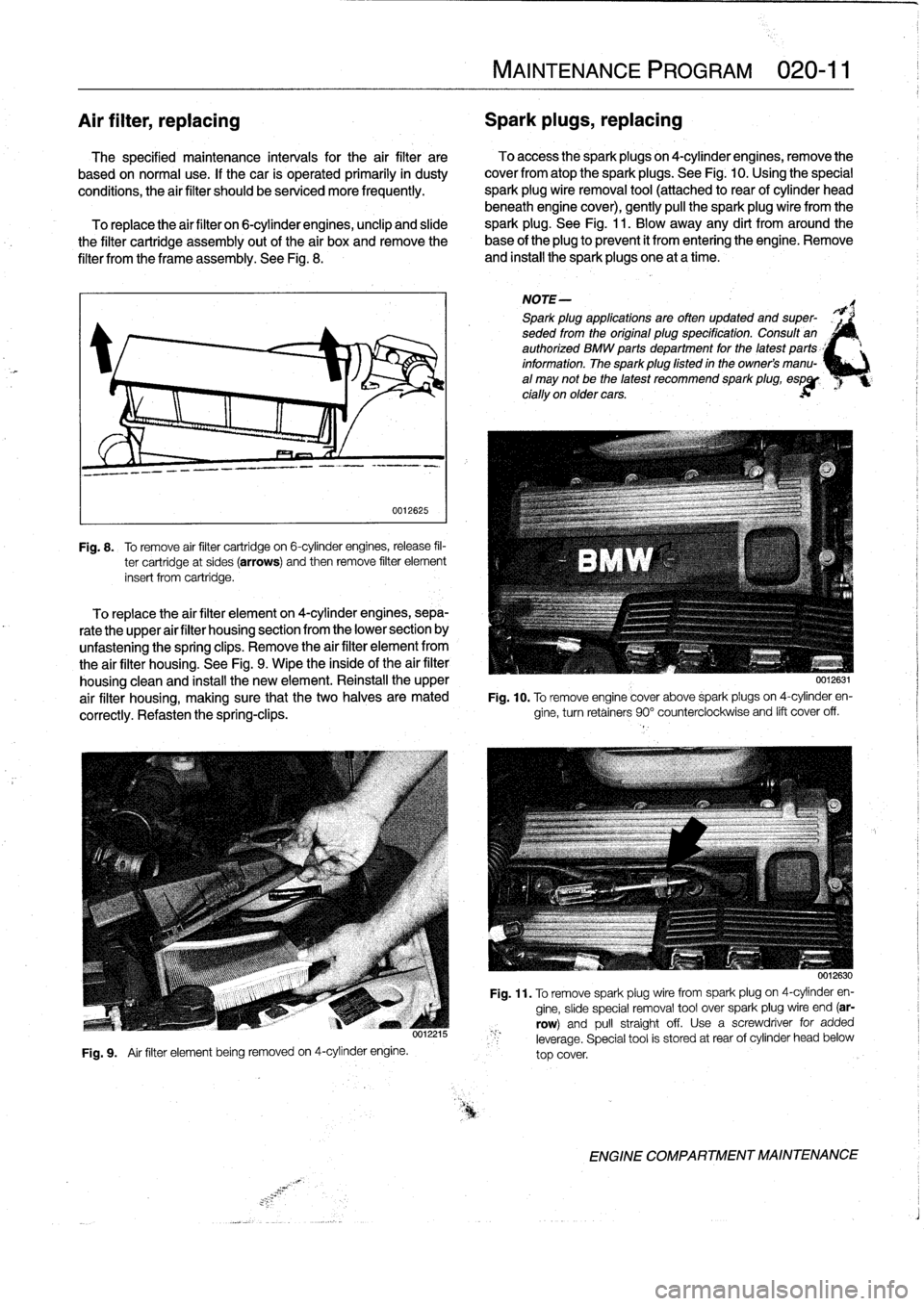
Air
filter,
replacing
Spark
plugs,
replacing
The
specified
maintenance
intervals
for
the
air
filter
are
To
access
the
spark
plugs
on
4-cylinder
engines,
remove
the
based
on
normal
use
.
If
thecar
is
operated
primarily
in
dusty
cover
fromatop
the
sparkplugs
.
See
Fig
.
10
.
Using
the
special
conditions,
the
air
filter
should
be
serviced
more
frequently
.
spark
plug
wire
removal
tool
(attached
to
rear
of
cylinder
head
beneath
engine
cover),
gently
pull
the
spark
plugwire
from
the
To
replace
the
air
filter
on
6-cylinder
engines,
unclip
and
sude
spark
plug
.
See
Fig
.
11
.
Blow
away
any
dirt
from
around
the
the
filter
cartridge
assembly
out
of
the
air
boxand
remove
the
base
of
the
plug
to
prevent
it
from
entering
theengine
.
Remove
filter
from
the
frame
assembly
.
See
Fig
.
8
.
and
install
the
spark
plugs
one
at
a
time
.
0012625
Fig
.
8
.
To
remove
air
filter
cartridge
on
6-cylinder
engines,release
fil-
ter
cartridge
at
sides
(arrows)
and
then
remove
filter
element
insert
from
cartridge
.
To
replace
the
air
filter
elementon
4-cylinder
engines,
sepa-
rate
the
upper
air
filter
housing
section
from
the
lower
section
by
unfastening
the
spring
clips
.
Remove
the
air
filter
element
from
the
air
filter
housing
.
See
Fig
.
9
.
Wipe
the
inside
of
the
air
filter
housing
clean
and
install
the
new
element
.
Reinstall
the
upper
air
filter
housing,
making
sure
that
the
two
halves
are
mated
correctly
.
Refasten
the
spring-clips
.
Fig
.
9
.
Air
filter
element
being
removed
on
4-cylinder
engine
.
MAINTENANCE
PROGRAM
020-
11
NOTE-
Spark
plug
applications
are
often
updated
and
super-
seded
from
the
original
plug
specification
.
Consuff
an
authorized
BMW
parts
department
for
the
latest
parts
_'
information
.
The
sparkplug
fisted
in
the
owners
manu-
al
may
not
be
the
latest
recommend
spark
plug,
espgp
cially
on
older
cars
.
0012631
Fig
.
10
.
To
remove
engine
cover
above
sparkpiugs
on
4-cylinder
en-
gine,
turnretainers
90°
counterclockwise
and
lift
cover
off
.
0012630
Fig
.
11
.
To
remove
spark
plugwirefrom
spark
plug
on
4-cylinder
en-
gine,
sude
special
removal
tool
over
spark
plug
wire
end
(ar-
row)
and
pull
straightoff
.
Usea
screwdriver
for
added
leverage
.
Special
tool
is
stored
at
rear
of
cylinder
head
below
top
cover
.
ENGINE
COMPARTMENT
MAINTENANCE
Page 36 of 759
020-
1
4
MAINTENANCE
PROGRAM
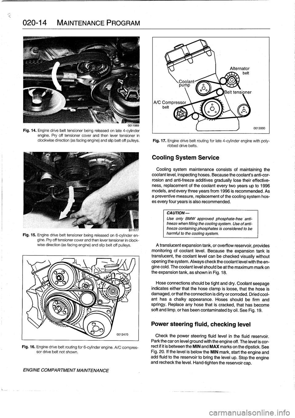
uu11989
Fig
.
14
.
Engine
drive
belt
tensíoner
being
released
on
late
4-cylinder
engine
.
Pry
off
tensioner
cover
and
then
lever
tensioner
in
clockwise
direction
(as
facing
engine)
and
slip
beltoff
pulleys
.
Fig
.
17
.
Engine
drive
belt
routing
for
late
4-cylinder
engine
with
poly-
ribbed
drivebelts
.
CA
UTION-
Use
only
BMW
approved
phosphate-free
anti-
freeze
when
filling
the
cooling
system
.
Use
of
anti-
B11177
freeze
containing
phosphates
!s
considerad
to
be
Fig
.
15
.
Engine
drive
belt
tensioner
being
released
on
6-cylinder
en-
harmful
to
the
cooling
system
.
gine
.
Pry
off
tensioner
cover
and
then
lever
tensioner
in
clock-
wise
direction
(as
facing
engine)
and
slipbelt
off
pulleys
.
A
translucent
expansion
tank,
or
overflow
resenroir,
providesmonitóring
of
coolant
leve¡
.
Because
the
expansion
tank
is
translucent,
thecoolant
level
can
be
checked
visually
without
opening
the
system
.
Always
check
thecoolant
leve¡
with
theen-gine
cold
.
The
coolant
leve¡
should
be
at
the
maximum
mark
on
O
o
'~
I
the
expansion
tank,
as
shown
in
Fig
.
18
.
OO
Hose
connectionhld
b
tiht
s
soueg
an
ddry
.
Coolánt
seepage
indicates
either
that
the
hose
clamp
is
loose,
that
the
pose
is
ENGINE
COMPARTMENT
MAINTENANCE
0012470
Fig
.
16
.
Engine
drive
belt
routing
for
6-cylinder
engine
.
A/C
compres-
sor
drive
belt
not
shown
.
'92
irá
Alternator
belt
Coolant~
0
pp
o0o
Belt
tensioner
Cooling
System
Service
0013000
Cooling
system
maintenance
consists
of
maíntaining
thecoolant
leve¡,
inspecting
hoses
.
Because
the
coolant's
anti-cor-
rosion
and
anti-freeze
additives
gradually
lose
their
effective-
ness,
replacement
of
thecoolant
every
two
years
up
to
1996
models,
and
every
three
years
from
1996
is
recommended
.
Asa
preventive
measure,
replacement
of
the
cooling
system
hos-
es
every
four
years
is
also
recommended
.
damaged,
or
that
the
connection
is
dirty
or
corroded
.
Dried
cool-
ant
has
a
chalky
appearance
.
Hoses
should
be
firm
and
springy
.
Replace
any
hose
that
is
cracked,
that
has
become
soft
and
limp,
or
has
been
contaminated
by
oil
.
See
Fig
.
19
.
Power
steering
fluid,
checking
leve¡
Check
the
power
steering
fluid
level
in
the
fluid
reservoir
.
Park
thecar
on
leve¡
ground
with
the
engine
off
.
The
level
is
cor-
rect
if
it
is
between
the
MIN
and
MAX
marks
on
the
dipstick
.
See
Fig
.
20
.
If
the
leve¡
is
below
the
MIN
mark,
start
the
engine
andadd
fluid
to
the
reservoir
to
bríng
the
leve¡
up
.
Stop
the
engine
and
recheck
the
leve¡
.
Hand-tighten
the
reservoir
cap
.
Page 40 of 759
020-
1
8
MAINTENANCE
PROGRAM
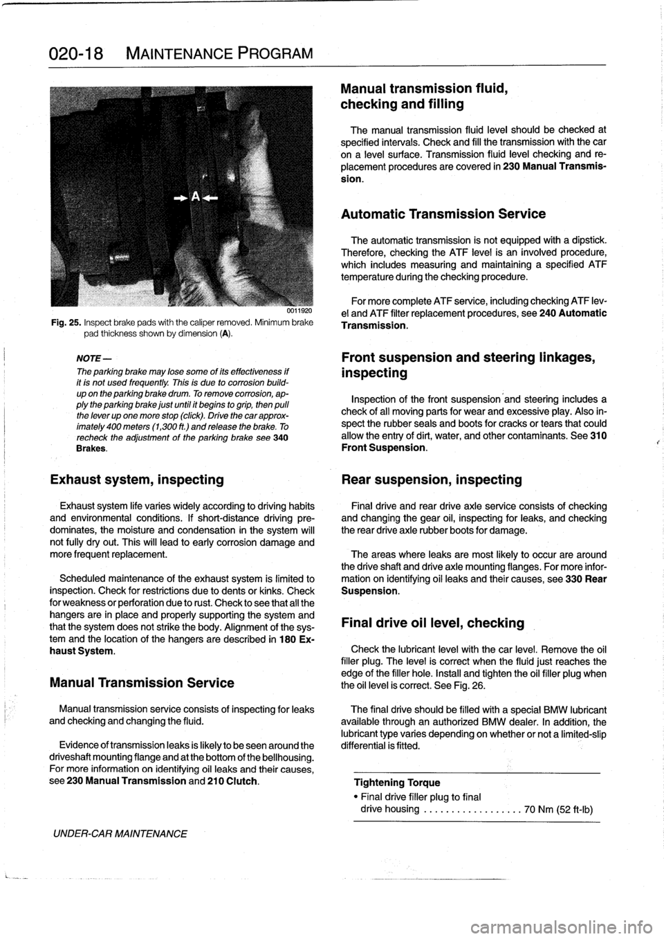
Fig
.
25
.
Inspect
brake
pads
with
the
caliper
removed
.
Minimum
brake
pad
thickness
shown
by
dimension
(A)
.
NOTE-
The
parking
brake
may
lose
some
of
its
effectiveness
if
it
is
not
used
frequently
.
This
is
due
to
corrosion
build-
up
on
the
parking
brake
drum
.
To
remove
corrosion,
ap-
plythe
parking
brake
just
until
it
begins
togrip,
then
pulí
the
lever
up
one
more
stop
(click)
.
Drive
thecar
approx-
imately
400
meters
(1,300
ft
.)
and
release
the
brake
.
To
recheck
the
adjustment
of
the
parking
brake
see340
Brakes
.
UNDER-CAR
MAINTENANCE
0011920
Manual
transmission
fluid,
checking
and
filling
The
manual
transmission
fluid
leve¡
should
be
checked
at
specified
intervals
.
Check
and
fill
the
transmission
with
the
car
ona
leve¡
surface
.
Transmission
(luid
leve¡
checking
and
re-
placement
procedures
are
covered
in
230
Manual
Transmis-
sion
.
Automatic
Transmission
Service
The
automatic
transmission
is
not
equipped
with
a
dipstíck
.
Therefore,
checking
the
ATF
level
is
an
ínvolved
procedure,
which
includes
measuring
and
maintaining
a
specified
ATF
temperature
during
the
checking
procedure
.
For
more
complete
ATF
service,
including
checking
ATF
lev-
e¡
and
ATF
filter
replacement
procedures,
see
240
Automatic
Transmission
.
Front
suspension
and
steering
linkages,
inspecting
Inspection
of
the
front
suspension'and
steering
includes
a
check
of
all
moving
parts
for
wear
and
excessive
play
.
Also
in-
spect
the
rubber
seals
and
boots
for
cracks
or
tears
that
could
allow
the
entry
of
dirt,
water,
and
other
contaminants
.
See
310
Front
Suspension
.
Exhaust
system,
inspecting
Rear
suspension,
inspecting
Exhaust
system
life
varies
widely
according
to
driving
habits
Final
drive
and
rear
drive
axle
service
consists
of
checking
and
environmental
conditions
.
If
short-distance
driving
pre-
and
changing
the
gear
oil,
inspecting
for
leaks,
and
checking
dominates,
the
moisture
and
condensation
in
the
system
will
the
rear
drive
axle
rubber
boots
for
damage
.
not
fully
dryout
.
This
will
lead
to
early
corrosion
damage
and
more
frequent
replacement
.
The
areas
where
leaks
are
most
likely
to
occur
are
around
the
driveshaft
and
drive
axle
mounting
flanges
.
For
more
infor
Scheduled
maintenance
of
the
exhaust
system
is
limitedlo
mation
on
ídentifying
oil
leaks
and
their
causes,
see330
Rear
inspection
.
Check
for
restrictions
due
to
dents
or
kinks
.
Check
Suspension
.
for
weakness
or
perforation
due
to
rust
.
Check
lo
see
that
all
the
hangers
are
in
place
and
properly
supporting
the
system
and
that
the
system
does
not
strike
the
body
.
Alignment
of
the
sys-
Final
drive
oil
leve¡,
checking
temand
the
location
of
the
hangers
aredescribed
in
180
Ex-
haust
System
.
Check
the
lubricant
leve¡
with
thecar
level
.
Remove
the
oil
filler
plug
.
The
leve¡
is
correct
when
the
fluidjust
reaches
the
edge
of
the
filler
hole
.
Install
and
tighten
the
oil
filler
plug
when
Manual
Transmission
Service
the
oil
level
is
correct
.
See
Fig
.
26
.
Manual
transmissionservice
consists
of
inspectingfor
leaks
The
final
drive
should
be
filled
with
a
special
BMW
lubricant
and
checking
and
changing
the
fluid
.
available
through
an
authorized
BMW
dealer
.
In
addition,
the
lubricant
type
varies
depending
onwhether
or
nota
limited-slip
Evidence
of
transmissionleaks
is
fkely
to
beseenaround
the
differential
is
fitted
.
driveshaft
mounting
flange
and
at
the
bottom
of
the
bellhousing
.
For
more
information
on
identifying
oil
leaks
and
their
causes,
see230ManualTransmissionand210
Clutch
.
Tightening
Torque
"
Finaldrive
filler
plug
to
final
drive
housing
..................
70
Nm
(52
ft-Ib)
Page 42 of 759
020-20
MAINTENANCE
PROGRAM
Seat
Belts
Washing
Chassis
Dirt
and
other
abrasive
particles
will
damage
seat
belt
web-
Periodic
washing
of
the
underside
of
the
car,
especially
in
bing
.
If¡t
is
necessary
to
clean
seat
belts,
use
a
mild
soap
solu-
winter,
will
help
prevent
accumulation
of
road
salt
and
rust
.
The
tion
.
Bleach
and
other
strong
cleaning
agents
may
weaken
the
besttime
to
wash
the
underside
is
just
after
the
car
has
been
belt
webbing
and
should
be
avoided
.
driven
in
wet
conditions
.
Spray
the
chassis
with
a
powerful
jet
of
water
.
Commercial
or
self-service
car
washes
may
not
be
best
WARNING-
for
this,
as
they
may
recycle
the
salt-contaminated
water
.
Do
not
clean
the
seat
belt
webbing
using
dry
clean-
ing
or
other
chemicals
.
Allow
wet
belts
to
dry
before
allowing
them
to
retract
.
Speeial
Cleaning
The
condition
of
the
belt
webbing
and
the
function
of
the
re-
tractor
mechanisms
should
be
inspected
.
See720
Seat
Belts
for
seat
belt
inspection
information
.
Exterior
Washing
The
longer
dirt
isleft
on
the
paint,
the
greater
the
risk
of
dam-
aging
the
glossy
finish,
either
by
scratching
or
by
the
chemical
effect
dirt
particles
may
have
on
the
paintedsurface
.
Do
not
wash
the
car
in
direct
sunlight
.
If
the
engine
hood
is
warm,
allow
it
to
cool
.
Beads
of
water
not
only
leavespots
when
dried
rapidly
by
the
sun
or
heat
from
the
engine,
but
also
can
act
as
small
magnifyingglasses
and
burn
spots
into
the
finish
.
Wash
thecar
with
a
mixture
of
lukewarmwater
and
a
car
wash
product
.
Rinse
using
plenty
of
clear
water
.
Wipe
the
body
dry
witha
soft
cloth
towel
or
chamois
to
prevent
water-spotting
.
Waxing
For
a
long-lasting,protective,
and
glossy
finish,
apply
a
hard
wax
after
thecar
has
been
washed
and
dried
.
Use
carnauba
or
synthetic
based
products
.
Waxing
is
not
needed
after
every
washing
.
You
can
tell
when
waxing
is
required
by
looking
at
the
finísh
when
it
is
wet
.
If
the
water
coats
the
paint
in
smooth
sheets
instead
of
forming
beads
that
rol¡
off,
a
new
coat
of
wax
is
needed
.
Wax
shouldnot
be
applied
to
black
trim
pieces,
rub-
ber,or
other
plastic
parts
.
Polishing
Use
paintpolish
only
if
the
finish
assumes
a
dull
lock
after
long
service
.
Polish
can
beused
to
remove
tar
spots
and
tar-
nish,
but
afterwards
a
coat
of
wax
should
be
applied
to
protect
the
clean
finish
.
Do
not
use
abrasive
polish
or
cleaners
on
alu-
minum
trimor
accessories
.
BODYAND
INTERIOR
MAINTENANCE
Cylinder
Head
and
Valvetrain
The
aluminum
cylinder
head
uses
chain-driven
double
overhead
camshafts
and
four
valves
per
cylinder
.
See
Fig
.
1
.
Tha
rvfinriar
hand
nmnlnve
n
ernceflnier
rineinn
fnr
nronter
Tar
spots
canbe
removed
with
a
bugand
tar
remover
.
Never
use
gasoline,
kerosene,
nail
polish
remover,
or
other
unsuitable
solvents
.
Insect
spots
also
respond
to
tar
remover
.
A
bit
of
bak-
ing
soda
dissolved
in
the
wash
water
will
facilitate
their
removal
.
This
method
can
also
beused
to
remove
spotting
from
tree
sap
.
Interior
Care
Dirt
spots
can
usually
be
removed
with
lukewarm
soapy
wa-
ter
or
a
dry
foam
cleaner
.
Use
spot
remover
for
grease
and
o¡I
spots
.
Do
not
pour
the
(quid
directly
on
the
carpetor
fabric,
but
dampen
a
clean
cloth
and
rub
carefully,starting
at
the
edge
of
the
spot
and
working
inward
.
Do
not
use
gasoline,
naptha,
or
other
flammable
substances
.
Leather
Upholstery
and
Trim
Leather
upholstery
and
trim
should
be
periodically
cleaned
using
a
slightly
damp
cotton
or
wool
cloth
.
The
idea
is
to
get
rid
of
the
dirtin
the
creases
and
pores
that
can
cause
brittleness
and
premature
aging
.
On
heavily
soiled
areas,
usea
mild
deter-
gent
(such
as
Woolite®)
or
other
specially
formulated
leather
r
cleaners
.
Use
two
tablespoons
to
one
quart
of
cold
water
.
Dry
the
trim
and
upholstery
completely
using
a
soft
cloth
.
Regular
use
of
agood
quality
leather
conditioner
will
reduce
drying
and
crackingof
the
leather
.
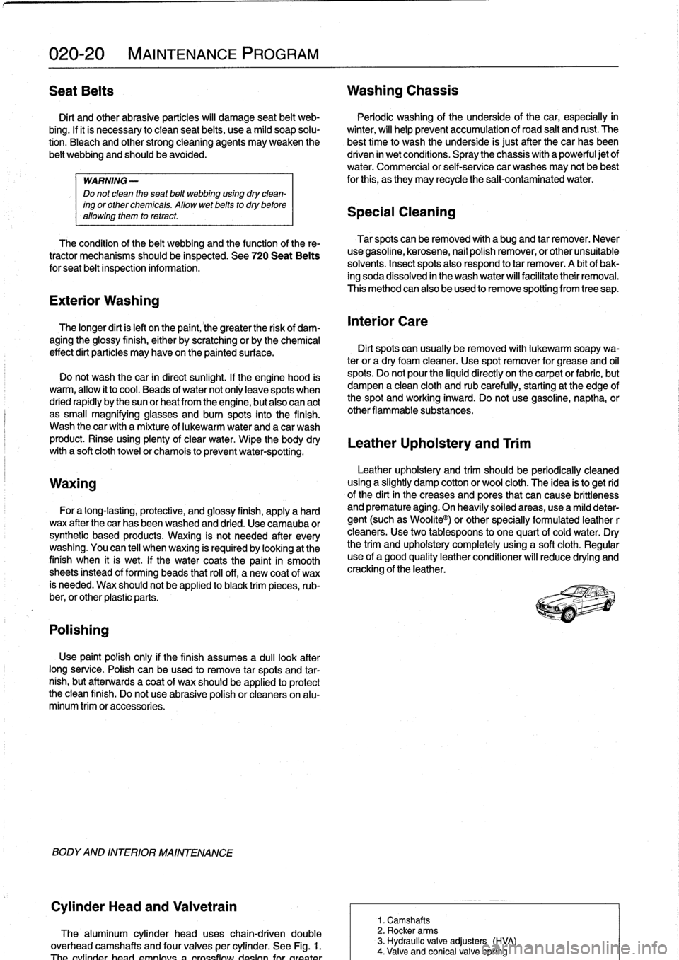
1
.
Camshafts
2
.
Rocker
arms
3
.
Hydraulic
valve
adjusters
(HVA)
4
.
Valve
and
conical
valve
spring
Page 48 of 759
100-6
ENGINE-GENERAL
Cylinder
compression,
checking
A
compression
tester
is
needed
to
make
a
compression
test
.
To
obtain
accurate
test
results,
the
battery
and
starter
must
be
capable
of
cranking
the
engine
at
250-300
rpm,
and
theen-
gine
should
be
at
normal
operating
temperature
.
Use
com-
pressed
air
to
clean
aroundthe
spark
plugs
before
removal
.
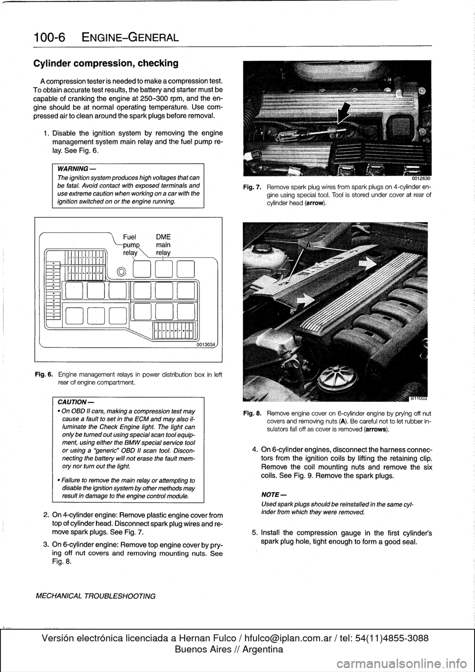
1
.
Disable
the
ignítion
system
by
removing
the
engine
management
system
main
relay
and
the
fuel
pump
re-
¡ay
.
See
Fig
.
6
.
WARNING
-
The
ignítion
system
produces
high
voltages
that
canbe
fatal
.
Avoid
contact
with
exposed
termínals
and
useextreme
caution
when
working
on
acar
wíth
the
ignítion
switched
on
or
the
engine
running
.
Fuel
DM
E
pump
main
re
ay
rel
ay
o
oa
ooa
.,
o00
oao
Fig
.
6
.
Engine
management
relays
in
power
distribution
box
inleft
rear
of
engine
compartment
.
CAUTION-
"
On
OBD
11
cars,
making
a
compression
test
may
causea
faultto
set
in
the
ECM
and
may
also
il-
luminate
the
Check
Engine
light
.
The
light
can
only
be
tumed
out
using
special
scan
tool
equip-
ment,using
eíther
the
BMW
specialservíce
tool
or
using
a
"generic"
OBD
11
scan
tool
.
Discon-
necting
the
battery
will
not
erase
the
fault
mem-
orynor
turn
outthe
light
.
0013034,
0012630
Fig
.
7
.
Remove
spark
plug
wires
from
spark
plugs
on
4-cylinder
en-
gine
using
special
tool
.
Tool
is
stored
under
cover
at
rear
of
cylinder
head
(arrow)
.
Fig
.
8
.
Remove
engine
cover
on
6-cylinder
engine
byprying
off
nut
covers
and
removing
nuts
(A)
.
Be
careful
not
to
let
rubber
in-
sulators
fall
off
as
cover
is
removed
(arrows)
.
4
.
On
6-cylinder
engines,
disconnect
the
harness
connec-
tors
from
the
ignítion
coils
by
lifting
the
retaining
clip
.
Remove
the
coil
mounting
nuts
andremove
the
six
coils
.
See
Fig
.
9
.
Remove
the
sparkplugs
.
"
Failure
to
remove
the
main
relay
or
attempting
to
disable
the
ignítion
system
by
other
methods
may
resultin
damage
to
the
engine
control
module
.
NOTE-
Used
sparkplugs
should
be
reinstalled
in
the
same
cyl-
2
.
On
4-cylinder
engine
:
Remove
plastic
engine
cover
from
inder
fromwhich
they
were
removed
.
top
of
cylinder
head
.
Disconnect
spark
plug
wires
and
re-
move
spark
plugs
.
See
Fig
.
7
.
5
.
Insta¡¡
the
compression
gauge
in
the
first
cylinder's
3
.
On
6-cylinder
engine
:
Remove
top
engine
coverby
pry-
spark
plug
hole,
tight
enough
to
form
a
good
seal
.
ing
off
nut
covers
and
removing
mounting
nuts
.
See
Fig
.
8
.
MECHANICAL
TROUBLESHOOTING
Page 53 of 759
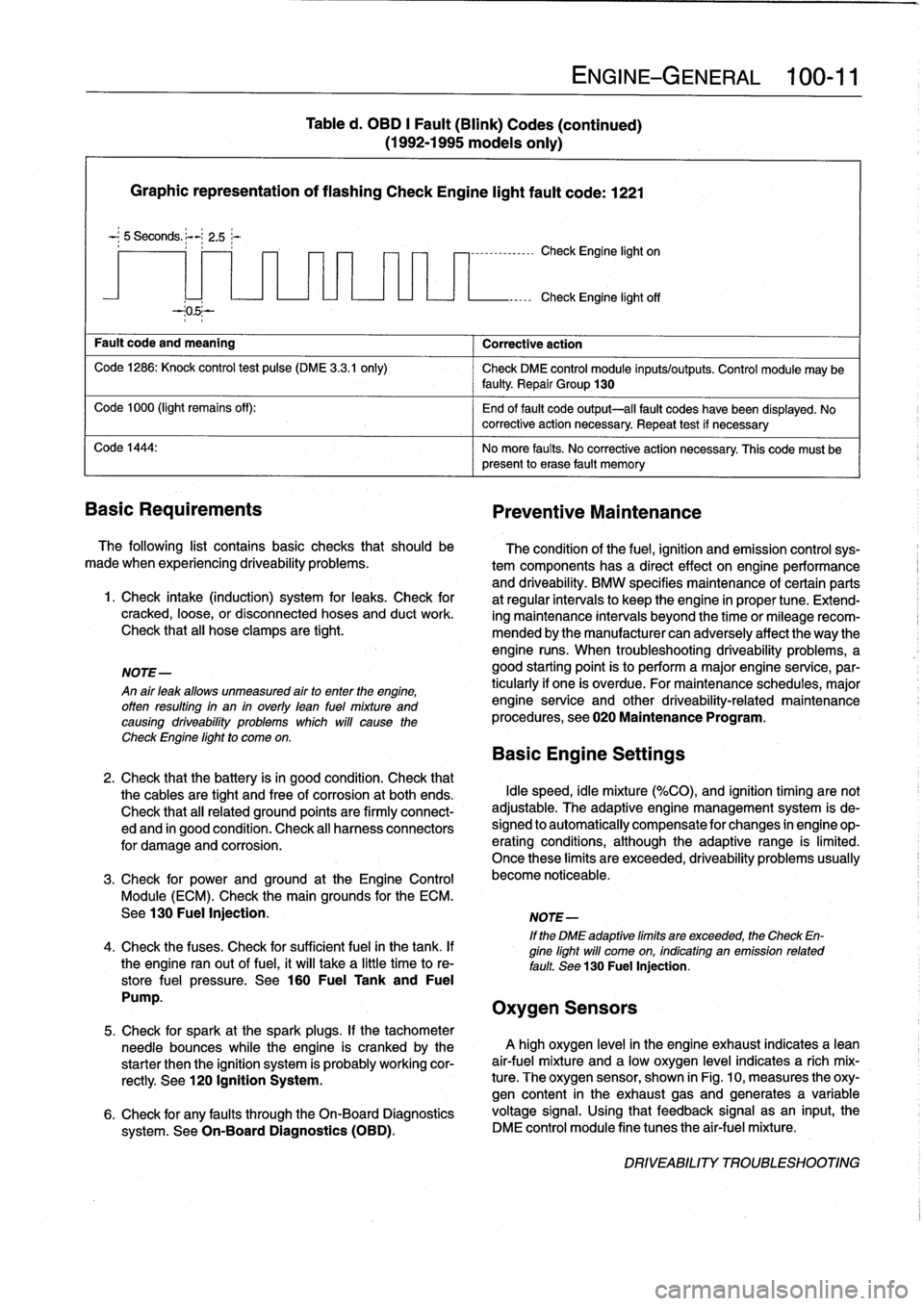
Graphic
representation
of
flashing
Check
Engine
light
fault
code
:
1221
-
;
5
Seconds
.
~-
2
.5;-
Fault
code
and
meaning
Corrective
action
Code
1286
:
Knock
control
test
pulse
(DME
3
.3
.1
only)
Check
DME
control
module
inputs/outputs
.
Control
module
may
be
faulty
Repair
Group
130
Code
1000
(light
remains
off)
:
End
of
fault
code
output-all
fault
codes
have
been
displayed
.
No
~
corrective
action
necessary
.
Repeat
test
if
necessary
Code
1444
:
No
more
faults
.
No
corrective
action
necessary
.
This
code
must
be
present
lo
erase
fault
memory
Basic
Requirements
Preventive
Maintenance
The
following
list
contains
basic
checks
that
should
be
made
when
experiencing
driveability
problems
.
1
.
Check
intake
(induction)
system
for
leaks
.
Check
for
cracked,
loose,
or
disconnected
hoses
and
duct
work
.
Check
that
all
hose
clamps
are
tight
.
NOTE-
An
air
leak
allows
unmeasured
airto
enter
the
engine,
offen
resulting
in
an
in
overly
lean
fuel
mixture
and
causing
driveability
problems
which
will
cause
the
Check
Engine
light
to
come
on
.
Table
d
.
OBD
I
Fault
(Blink)
Codes
(continued)
(1992-1995
models
only)
7
-
1
--------------
Check
Engine
light
on
ENGINE-GENERAL
100-
1
1
Check
Engine
light
off
The
condition
of
the
fuel,
ignition
and
emission
controlsys-
tem
components
has
a
directeffect
onengineperformance
and
driveability
.
BMW
specifies
maintenance
of
certain
parts
at
regular
intervals
lo
keep
the
engine
in
proper
tune
.
Extend-
ing
maintenance
intervals
beyond
the
time
or
mileagerecom-
mended
bythe
manufacturer
can
adversely
affect
the
way
the
engine
runs
.
When
troubleshooting
driveability
problems,
a
good
starting
point
is
to
perform
a
major
engine
service,par-
ticularly
if
one
is
overdue
.
For
maintenance
schedules,
major
engine
service
and
other
driveability-related
maintenance
procedures,
see020
Maintenance
Program
.
Basic
Engine
Settings
2
.
Check
that
the
battery
isin
good
condition
.
Check
that
the
cables
are
tight
and
free
of
corrosion
at
both
ends
.
Idle
speed,
idle
mixture
(%CO),
and
ignition
timing
are
not
Check
that
all
related
ground
points
are
firmly
connect-
adjustable
.
The
adaptive
engine
management
system
is
de-
ed
and
in
good
condition
.
Check
al¡
harness
connectors
signed
lo
automatically
compensate
for
changes
in
engine
op-
for
damage
and
corrosion
.
erating
conditions,
although
the
adaptive
range
is
limited
.
Once
these
limits
are
exceeded,
driveability
problems
usually
3
.
Check
for
prwer
and
ground
at
the
Engine
Control
become
noticeable
.
Module
(ECM)
.
Check
the
main
grounds
for
the
ECM
.
See130
Fuel
Injection
.
NOTE-
If
the
DME
adaptive
limits
are
exceeded,
the
Check
En-
4
.
Check
the
fuses
.
Check
for
sufficient
fuel
in
the
tank
.
If
gine
light
will
come
on,
indicating
an
emission
related
the
engine
ranout
of
fuel,
it
will
take
a
little
time
to
re-
fault
.
See
130
Fuel
Injection,
store
fuel
pressure
.
See
160
Fuel
Tank
and
Fuel
Pump
.
Oxygen
Sensors
5
.
Check
for
spark
at
the
spark
plugs
.
If
the
tachometer
needle
bounces
while
the
engine
is
crankedby
the
A
high
oxygen
level
in
the
engine
exhaust
indicates
a
lean
starter
then
the
ignition
system
is
probably
working
cor-
air-fuel
mixture
and
a
low
oxygen
level
indicates
a
rich
mix
rectly
.
See
120
Ignition
System
.
ture
.
The
oxygen
sensor,
shown
in
Fig
.
10,
measures
the
oxy-
gen
content
in
the
exhaust
gasand
generates
a
variable
6
.
Check
for
any
faults
through
the
On-Board
Diagnostics
voltage
signal
.
Using
that
feedback
signal
asan
input,
the
system
.
See
On-Board
Diagnostics
(OBD)
.
DME
control
module
fine
tunes
the
air-fuel
mixture
.
DRIVEABILITY
TROUBLESHOOTING
Page 59 of 759
110
Engine
Removal
and
Installation
GENERAL
.
.
.
.
.......
.
.
.
..........
.
...
110-1
Engine,
removing
and
installing
(4-cylinder
engines)
.
..
.....
..
...........
110-1
ENGINE
REMOVAL
AND
INSTALLATION
110-1
Engine,
removing
and
installing
(6-cylinder
engines)
..
...
...
..
.....
..
....
110-4
GENERAL
Some
special
tools
are
required
for
removal
and
installation
of
the
engine
.
Be
sure
to
have
the
necessary
equipment
on
hand
before
starting
thejob
.
CAUTION-
"
Engine
removal
requires
disconnecting
the
bat-
tery
.
This
may
erase
any
system
fault
code(s)
that
havebeen
stored
in
control
unit
memories
.
Check
forfault
codes
prior
to
disconnecting
the
battery
cables
.
"
If
the
Check
Engine
lightis
illuminated
with
the
engine
running,
see
100
Engine-General
for
On-Board
Diagnostics
(08D)
fault
code
infor-
mation
.
"
If
any
other
system
faults
have
been
detected,
as
indicated
by
an
illuminated
ANTI
LOCK,
SRS
or
AST
warning
light,
see
the
appropriate
repair
group
inthis
manual
or
an
authorized
BMW
dealer
for
more
information
on
fault
codes
.
ENGINE
REMOVALAND
INSTALLATION
Engine,
removing
and
installing
(4-cylinder
engines)
Cover
al¡
painted
surfaces
before
beginning
theremoval
procedure
.
Asan
aid
to
installation,
label
al¡
components,
wires,
and
hoses
before
removing
them
.
Do
not
reuse
gas-
kets,
O-rings
or
seals
during
reassembly
.
WARNING
-
Due
to
risk
of
personal
injury,
be
sure
the
engine
is
cold
before
beginning
the
removalprocedure
.
1.
Disconnect
negative
(-)
cable
from
battery
in
luggage
compartment
.
0011969
CAUTION-
Prior
to
disconnecting
the
battery,
read
the
battery
disconnection
cautions
given
at
the
front
of
this
manual
on
page
viii
.
ENGINE
REMOVAL
AND
INSTALLATION
110-1
2
.
Remove
transmission
from
car
.
See230
Manual
Transmission
or
240
Automatic
Transmission
.
3
.
Remove
enginehood
or
place
hood
in
service
positíon
.
See
410
Fenders,
Engine
Hood
.
NOTE-
tt
is
notnecessary
to
remove
the
engine
hood,
but
it
is
helpful
and
will
make
engine
removal
and
installation
easier
.
4
.
Remove
splash
guard
under
engine,
if
applicable
.
5
.
Unbolt
ignition
coil
assembly
from
bracket
on
strut
tow-er
.
Disconnect
wiring
to
ignition
cofs,
then
place
coil
assembly
on
engine
.
6
.
Disconnect
al¡
cables
and
harness
connectors
at
throt-
tle
housing
.
7
.
Unbolt
andremove
complete
air
cleaner
housing
with
mass
air
flow
sensor,
disconnecting
and
labeling
con-
nectors,
ducting
and
hoses
asnecessary
.
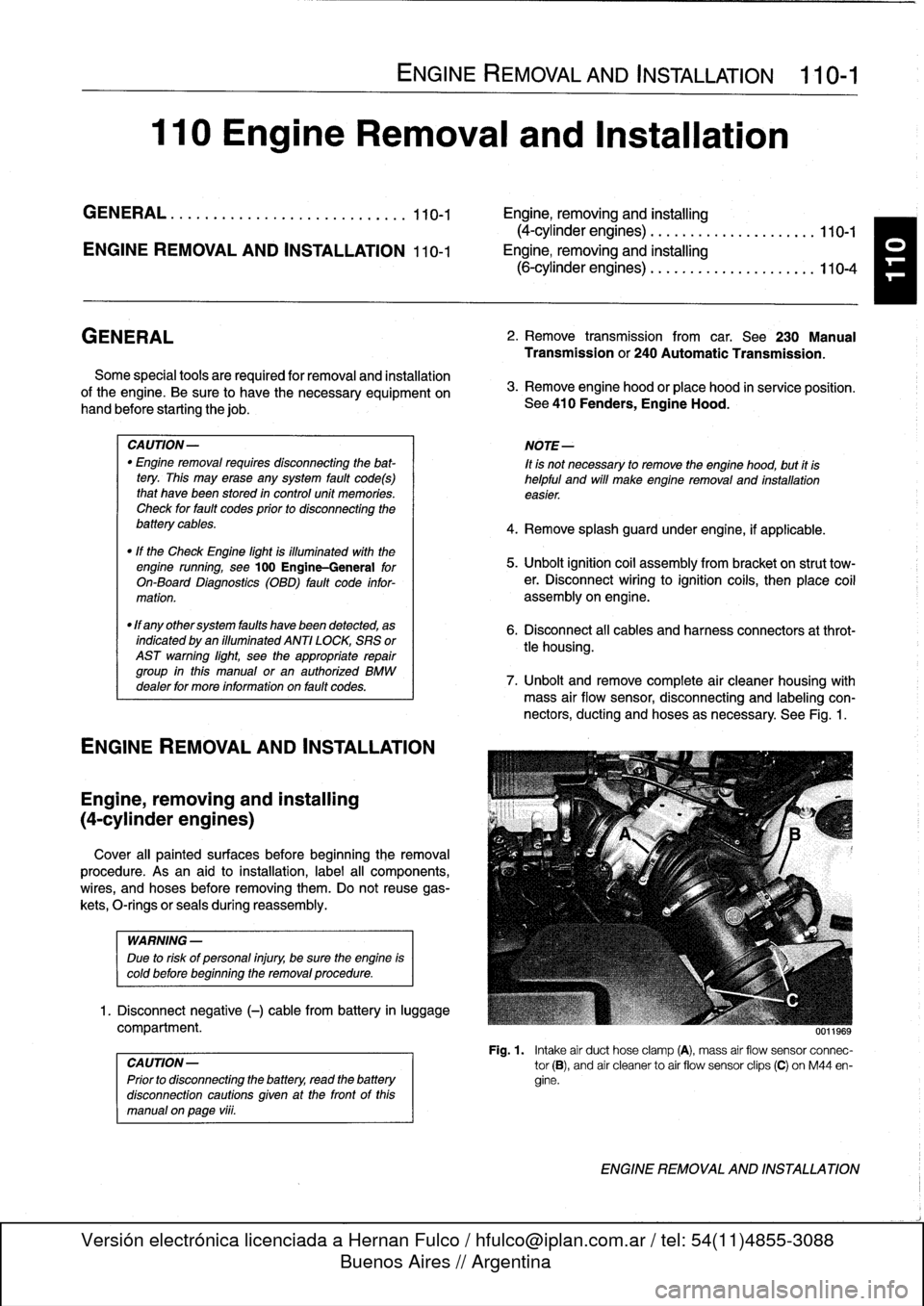
See
Fig
.
1
.
Fig
.
1
.
Intake
air
duct
hose
clamp
(A),
mass
air
flow
sensor
connec-
tor
(B),
and
air
cleanerto
air
flow
sensor
clips
(C)
on
M44
en-
gine
.
ENGINE
REMOVAL
AND
INSTALLATION
Page 62 of 759
110-
4
ENGINE
REMOVAL
AND
INSTALLATION
Engine,
removing
and
installing
(6-cylinder
engines)
Engineremoval
procedures
for
the
various
6-cylinder
en-
gines
arecovered
in
this
section
.
Most
steps
in
theproce-
dures
are
similar
or
the
same
for
al¡
engines
.
Specific
differences
that
apply
are
noted
at
the
beginning
of
each
step
.
Be
sure
to
cover
all
painted
surfaces
before
beginning
the
removal
procedure
.
As
an
aid
to
installation,
label
all
compo-
nents,wires,
and
hoses
before
removing
them
.
Do
not
reuse
gaskets,
O-rings
or
seals
during
reassembly
.
WARNING
-
Due
to
risk
of
personal
injury,
be
sure
the
engine
is
cold
before
beginning
the
removalprocedure
.
1
.
Disconnect
negative
(-)
battery
cable
in
luggage
com-
partment
.
CAUTION-
Prior
to
disconnecting
the
battery,
read
the
battery
disconnection
cautions
given
at
the
front
of
this
manual
onpage
vi¡¡
.
2
.
Remove
engine
hood
or
place
hood
in
service
position
.
See410
Fenders,
Engine
Hood
.
NOTE-
1t
is
not
necessary
to
remove
the
engine
hood,
but
it
is
helpful
and
will
make
engine
removal
and
installation
easier
.
3
.
Remove
splash
guardunder
engine,
if
applicable
.
4
.
Remove
transmission
from
car
.
See
230
Manual
Transmission
or
240Automatic
Transmission
.
5
.
Remove
vacuum
hosefrom
brake
booster
on
bulkhead
.
Cover
hole
in
booster
and
plug
hose
end
.
6
.
Remove
intake
air
plenum
panel
in
rear
of
engine
com-
partment
.
See
640
Heating
and
AirConditioning
.
7
.
Remove
ground
strap
from
timing
case
cover,
if
appli-
cable
.
8
.
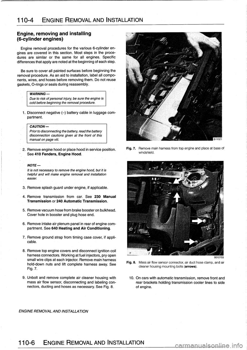
Remove
top
enginecovers
and
disconnect
ignition
coil
harness
connectors
.
Working
at
fuel
injectors,
pry
open
small
wire
clipsat
each
injector
.
Remove
main
harness
hold-down
nuts
and
lift
completeharness
away
.
See
Fig
.
7
.
ENGINE
REMOVAL
AND
INSTALLATION
Fig
.
7
.
Remove
mainharnessfrom
top
engine
and
place
at
base
of
windshield
.
0012703
Fig
.
8
.
Mass
air
flow
sensor
connector
air
duct
hose
clamp,
and
air
cleaner
housing
mounting
bolts
(arrows)
.
9
.
Unbolt
andremove
complete
air
cleaner
housing
with
10
.
On
cars
with
automatic
transmission,
remove
front
and
mass
air
flow
sensor,
disconnecting
and
labeling
con-
rearbrackets
holding
transmission
cooler
linesto
side
nectors,
ducting
and
hoses
asnecessary
.
See
Fig
.
8
.
of
engine
.
Page 67 of 759
113
Cylinder
Head
Removal
and
Installation
GENERAL
.
...............
.
.
.
.
.
.......
113-1
CYLINDER
HEAD,
6-CYLINDER
.
.
.
.
.
.
.
113-10
Cylinder
head,
removing
(6-cylinder
engine)
..
113-10
CYLINDER
HEAD,
4-CYLINDER
..
.
...
.
.
113-1
Cylinder
head,
installing
(6-cylinder
engine)
...
113-15
Cylinder
head,
removing
(4-cylinder
engine)
...
113-1
E
Cylinder
head,
installing
(4-cylinder
engine)
...
113-6
GENERAL
CYLINDER
HEAD,
4-CYLINDER
The
information
given
inthis
repair
group
assumes
that
the
engine
is
installed
in
the
engine
bay
.
For
cylinder
head,
cam-
Cylinder
head,
removing
shaft,
and
valvetrain
disassembly
and
reconditioning
informa-
(4-cylinder
engine)
tion,
see116
Cylinder
Head
and
Valvetrain
.
For
ease
of
use
this
removal
procedure
is
broken
into
sub-
In
the
procedures
given
below,
engines
are
referred
to
by
sections,
as
follows
:
engine
code
.
If
necessary,
see100
Engine-General
for
en-
gine
code
and
application
information
.
NOTE-
If
a
head
gasket
problem
is
suspected,
acompression
test
will
usually
detectthe
fault
.
See
100
Engine-Gen-
eral
for
compression
testing
information
.
Special
BMW
service
tools
are
required
to
properly
remove
and
install
the
cylinder
head
on
both
the
4-cylinder
and
6-cyl-
inder
engines
.
The
special
tools
are
used
to
time
the
val-
vetrain
to
the
crankshaft
and
to
remove
the
Torx
(El
2)
head
bolts
.
Read
the
procedure
through
before
beginning
thejob
.
Cover
al¡
painted
surfaces
before
beginning
the
removal
procedure
.
As
an
aid
to
installation,
label
all
components,
wires,
and
hoses
before
removing
them
.
Do
not
reuse
gas-
kets,
O-rings
or
seals
during
reassembly
.
WARNING
-
Due
to
risk
of
personal
injury,
be
sure
the
engine
is
cold
before
beginning
the
removalprocedure
.
CYLINDER
HEAD
REMOVAL
AND
INSTALLATION
113-1
General
Coolingsystem,
draining
Cylinder
head
cover,
removing
Intake
manifold,
removing
Timing
chains,
uncoupling
Cylinder
head
assembly,
removing
WARNING
-
Allow
engine
to
cool
before
beginning
this
proce-
dure
.
General
1
.
Disconnect
negative
(-)
cable
from
battery
.
CAUTION
-
"
Prior
to
disconnectiog
the
battery,
read
the
bat-
tery
disconnection
cautions
given
at
the
front
of
this
manual
on
page
viii
.
"
Disconnecting
the
battery
may
erase
fault
codees)
stored
in
control
module
memory
.
Check
for
fault
codes
using
special
BMW
diagnostic
equipment
.
NOTE-
The
battery
is
mounted
in
the
luggage
compartment
behind
the
right
side
trim
panel
.
2
.
Working
underneath
vehicle,
remove
front
exhaust
pipe
from
exhaust
manifold
.
See
Fig
.
1
.
3
.
Disconnect
vacuum
hose
fitting
from
brake
booster
on
rear
bulkhead
.
Plug
opening
in
booster
and
hose
end
.
CYLINDER
HEAD,
4-CYLINDER
Page 71 of 759
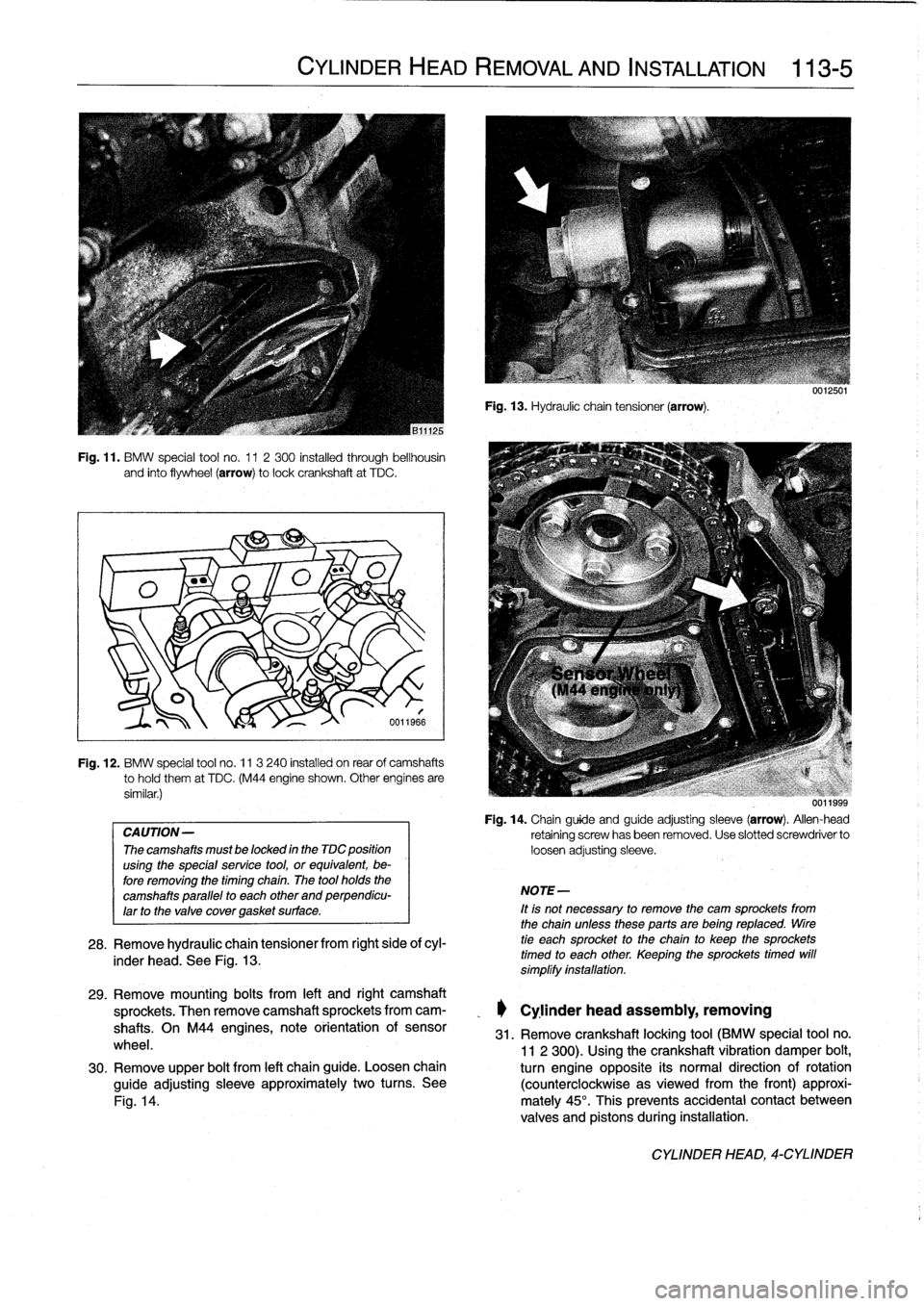
Fig
.
11
.
BMW
special
tool
no
.
11
2300
installed
through
bellhousin
and
finto
flywheel
(arrow)
tolockcrankshaft
at
TDC
.
Fig
.
12
.
BMW
special
tool
no
.
11
3
240
installed
on
rear
of
camshafts
tohold
them
at
TDC
.
(M44
engine
shown
.
Other
engínes
are
similar
.)
CAUTION-
The
camshafts
must
be
locked
in
the
TDC
position
using
the
special
service
tool,
or
equivalent,
be-
fore
removing
the
timing
chaín
.
The
tool
holds
the
camshafts
parallel
to
each
other
and
perpendicu-
larto
the
valve
covergasket
surface
.
CYLINDER
HEAD
REMOVAL
AND
INSTALLATION
113-5
6011966
28
.
Remove
hydraulic
chain
tensiones
from
right
side
ofcyl-
inder
head
.
See
Fig
.
13
.
Fig
.
13
.
Hydraulic
chain
tensioner
(arrow)
.
NOTE-
It
is
not
necessary
to
remove
the
cam
sprockets
from
the
chainuntessthese
parts
are
being
reptaced
.
tire
tie
each
sprocket
to
the
chain
to
keep
the
sprockets
timed
to
each
other
.
Keeping
the
sprockets
timed
will
símplífy
instaftation
.
uu
11999
Fig
.
14
.
Chainguide
and
guide
adjusting
sleeve
(arrow)
.
Allen-head
retaining
screwhasbeen
removed
.
Use
slotted
screwdriver
to
loosen
adjusting
sleeve
.
29
.
Remove
mounting
bolts
from
left
and
right
camshaft
sprockets
.
Then
remove
camshaft
sprockets
from
cam-
_
Cylinder
head
assembly,
removing
shafts
.
On
M44
engines,
note
orientation
of
sensor
31
.
Remove
crankshaft
locking
tool
(BMW
special
tool
no
.
wheel
.
11
2
300)
.
Usingthe
crankshaft
vibration
damper
bolt,
30
.
Remove
upper
bolt
from
left
chainguide
.
Loosen
chain
turn
engine
opposite
its
normal
direction
of
rotation
guide
adjusting
sleeve
approximately
two
turns
.
See
(counterclockwise
asviewed
from
the
front)
approxi
Fig
.
14
.
mately
45°
.
This
prevents
accidental
contact
between
valves
and
pistons
during
installation
.
CYLINDER
HEAD,
4-CYLINDER