trunk BMW 318i 1997 E36 Owner's Manual
[x] Cancel search | Manufacturer: BMW, Model Year: 1997, Model line: 318i, Model: BMW 318i 1997 E36Pages: 759
Page 404 of 759
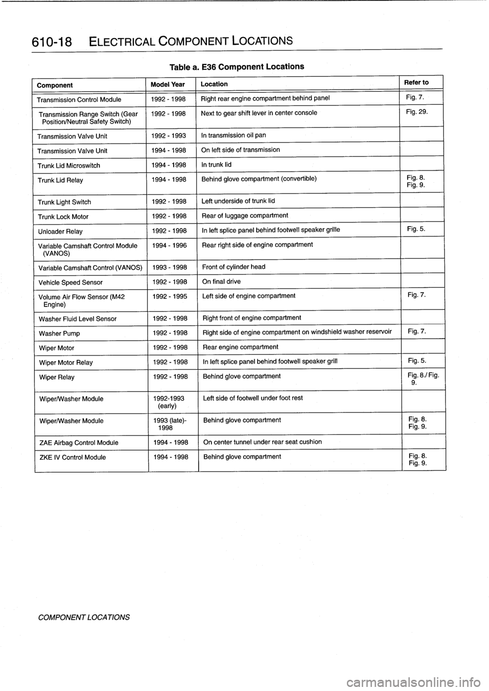
610-18
ELECTRICAL
COMPONENT
LOCATIONS
Tablea
.
E36
Component
Locations
Component
Model
Year
Location
Refer
to
Transmission
Control
Module
1992-1998
Right
rear
engine
compartment
behíndpanel
Fig
.
7
.
Transmission
Range
Switch
(Gear
1992-1998
Next
to
gear
shift
lever
in
center
console
Fig
.
29
.
Position/Neutra
l
Safety
Switch)
Transmission
Valve
Unít
1992-1993
In
transmission
oil
pan
Transmission
Valve
Unit
1994-1998
On
left
side
of
transmission
Trunk
Lid
Microswitch
1994-1998
In
trunk
lid
Trunk
Lid
Relay
1994-1998
Behind
glove
compartment
(convertible)
Fig
.
8
.
Fig
.
9
.
Trunk
Light
Switch
1992-1998
Left
underside
of
trunk
lid
TrunkLockMotor
1992-1998
Rear
of
luggage
compartment
UnloaderRelay
1992-1998
Inleft
splice
panel
behind
footwell
speaker
grille
Fig
.
5
.
Variable
Camshaft
Control
Module
1994-1996
I
Rear
right
side
of
engine
compartment
(VANOS)
Variable
Camshaft
Control
(VANOS)
1993-1998
Front
ofcylinder
head
Veh¡cle
Speed
Sensor
1992-1998
On
final
drive
Volume
Air
Flow
Sensor
(M42
1992-1995
Left
side
of
engine
compartment
Fig
.
7
.
Engine)
Washer
Fluid
Leve¡
Sensor
1992-1998
Right
frontof
engine
compartment
Washer
Pump
1992-1998
Right
side
of
engine
compartment
on
windshield
washer
reservoir
Fig
.
7
.
Wiper
Motor
1992-1998
Rear
engine
compartment
Wiper
Motor
Relay
1992-1998
Inleft
splice
panel
behind
footwell
speaker
grill
Fig
.
5
.
Wiper
Relay
1992-1998
(
Behind
glove
compartment
I
Fig
.
8
./
Fig
.
9
.
Wiper/Washer
Module
1992-1993
Left
side
of
footwell
under
foot
rest
(early)
Wiper/Washer
Module
1993
(late)-
Behind
glove
compartment
Fig
.
8
.
1998
1
Fig
.
9
.
ZAE
Airbag
Control
Module
1
1994-1998
1
On
center
tunnel
under
rear
seat
cushion
ZKE
IV
Control
Module
1994-1998
I
Behind
glove
compartment
Fig
.
8
.I
Fig
.
9
.
COMPONENT
LOCATIONS
Page 429 of 759
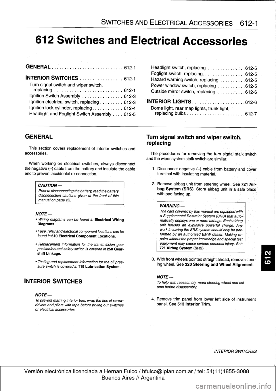
612
Switches
and
Electrical
Accessories
GENERAL
.
.
.
.
.
.
.
.
.
...
.
.
.
.
.
...
.
......
.612-1
Headlight
switch,
replacing
..
.
...
.
.
.
.
.
.
.
.
.
612-5
Foglight
switch,
replacing
....
.
.
.
.
.
.
.
.
.
.
.
.
.
612-5
INTERIOR
SWITCHES
.
.
...
.
.
.
.
.
.
.
.....
612-1
Hazard
warning
switch,
replacing
.
.
.
.
.
.
.
.
.
.612-5
Turn
signal
switch
and
wiper
switch,
Powerwindow
switch,
replacing
.
.
.
...
.
.
.
.
.
612-5
replacing
.
.
.
.
.
.
.
...
.
.
.
.....
.
....
.
.
.
.
612-1
Outside
mirrorswitch,
replacing
.
.
.
.
.....
.
.
.612-6
Ignition
Switch
Assembly
.
.
.
.
.
.
.
.
....
.
...
612-3
Ignition
electrical
switch,
replacing
.
...
.
....
612-3
INTERIOR
LIGHTS
.
.
................
.
..
612-6
Ignition
lock
cylinder,
replacing
.
.
.
.
.....
.
..
612-4
Dome
light,
rear
map
lights,
trunk
light,
Headlight
and
Foglight
Switch
Assembly
.
.
.
.
612-5
replacing
bulbs
.
......
.
.
.
.
.
.
.
.
.
.....
.
.612-7
GENERAL
Turn
signal
switch
and
wiper
switch,
replacing
Thissection
covers
replacement
of
interior
switches
and
accessories
.
The
procedures
for
removing
the
turn
signal
stalk
switch
and
the
wiper
system
stalk
switchare
similar
.
When
working
on
electrical
switches,
always
disconnect
the
negative
(-)
cable
from
the
battery
and
insulate
the
cable
end
to
prevent
accidental
re-connection
.
CAUTION-
Prior
to
disconnectiog
the
battery,
read
the
battery
disconnection
cautions
given
at
the
front
of
this
manual
on
page
viii
.
WARNING
-
The
cars
covered
by
this
manual
are
equipped
with
a
Supplemental
Restraint
System
(SRS)
that
auto-'
matically
deploys
one
or
more
airbags
.
Each
airbag
unit
houses
an
explosive
powerful
charge
.
Any
work
involving
the
SRS
system
should
only
be
per-
formed
byan
authorized
BMW
dealer
.
Making
re-
pairs
without
the
proper
knowledge
and
special
test
equipment
may
cause
serious
personal
injury
.
See
721
Airbag
System
(SRS)
3
.
With
front
wheels
pointed
straight
ahead,
remove
steer-
"
Testing
and
replacement
information
for
the
oil
ores-
¡ng
wheel
.
See
320
Steering
and
Wheel
Alignment
.
sure
switch
is
covered
in
119
Lubrication
System
.
NOTE-
"
Wirfng
diagramscan
be
found
in
Electrical
Wiring
Diagrams
.
"
Fuse,
relay
and
electrical
component
locations
can
be
found
in
610
Electrical
Component
Locations
.
"
Replacement
information
for
thetransmission
gear
position/neutral
safety
switch
is
covered
in
250
Gear-
shift
Unkage
.
INTERIOR
SWITCHES
NOTE
-
To
preventmarring
interior
trim,
wrap
the
tips
of
screw-
drivers
and
pliers
with
tape
beforeprying
out
switches
or
electrical
accessories
.
SWITCHES
AND
ELECTRICAL
ACCESSORIES
612-1
1
.
Disconnect
negative
(-)
cable
from
battery
and
cover
terminal
with
insulating
material
.
2
.
Remove
airbag
unit
from
steering
wheel
.
See
721
Air-
bag
System
(SRS)
.
Store
airbag
unit
in
a
safe
placew¡th
pad
facing
up
.
NOTE
-
To
helo
with
reassembly,
mark
steering
wheel
and
col-
umn
before
disassembly
.
4
.
Remove
trim
panel
from
lower
left
side
of
instrument
panel
.
See513
Interior
Trim
.
INTERIOR
SWITCHES
Page 434 of 759
612-6
SWITCHES
AND
ELECTRICAL
ACCESSORIES
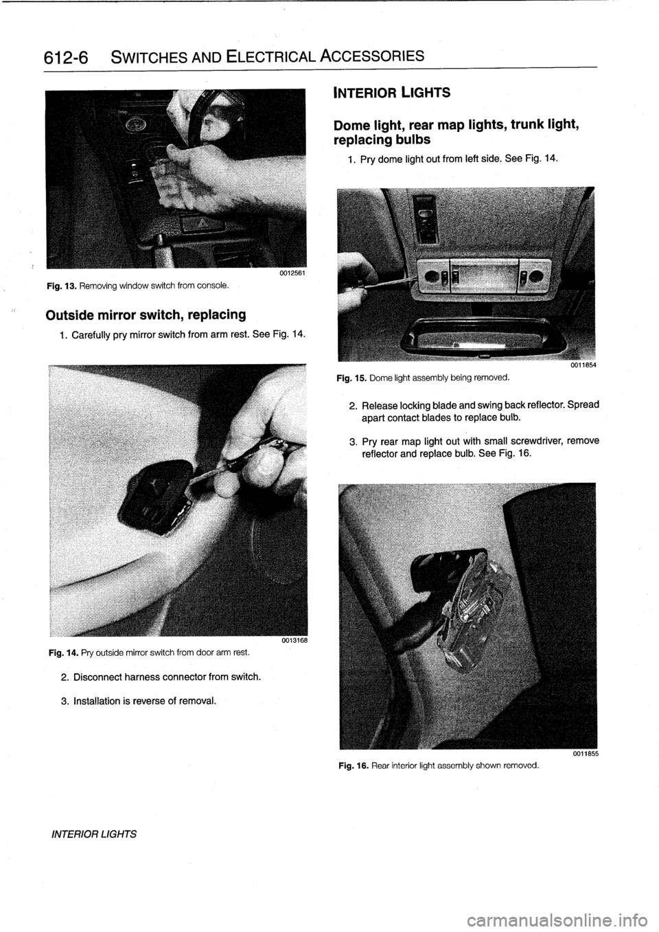
Fig
.
13
.
Removing
window
switch
from
console
.
Outside
mirror
switch,
replacing
0012561
1
.
Carefully
pry
mirror
switch
from
arm
rest
.
See
Fig
.
14
.
Fig
.
14
.
Pry
outside
mirror
switch
from
door
arm
rest
.
2
.
Disconnectharness
connector
from
switch
.
3
.
Installation
is
reverseof
removal
.
INTERIOR
LIGHTS
0013168
INTERIOR
LIGHTS
Dome
light,
rear
map
lights,
trunk
light,
replacing
bulbs
1
.
Pry
dome
light
out
from
left
side
.
See
Fig
.
14
.
Fig
.
15
.
Dome
light
assembly
being
removed
.
2
.
Release
locking
blade
and
swing
back
reflector
.
Spread
apart
contact
blades
toreplace
buib
.
3
.
Pry
rear
map
light
out
with
small
screwdriver,
remove
reflector
and
replace
bulb
.
See
Fig
.
16
.
Fig
.
16
.
Rear
interior
light
assembly
shown
removed
.
0011855
Page 435 of 759
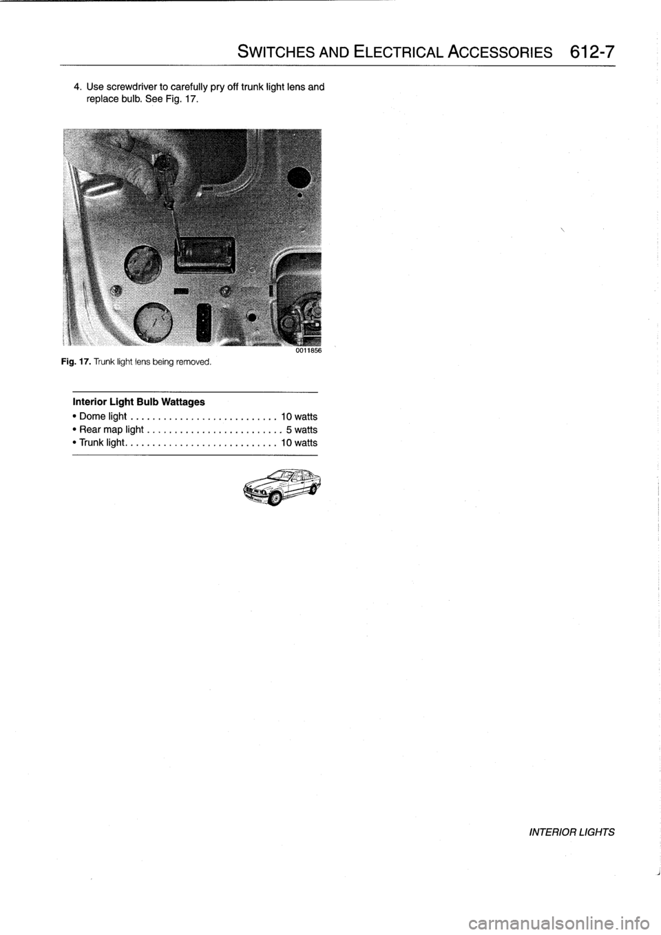
4
.
Use
screwdriver
to
carefully
pry
off
trunk
light
lens
and
replace
bulb
.
See
Fig
.
17
.
Fig
.
17
.
Trunk
light
lens
being
removed
.
Interior
Light
Bulb
Wattages
"
Dome
light
..
..
.
..
..
..................
10
watts
"
Rear
map
light
.
.
.
.
.
....................
5
watts
"
Trunk
light
...
..
.
..
....................
10
watts
SWITCHES
AND
ELECTRICAL
ACCESSORIES
612-7
uulio56
INTERIOR
LIGHTS
Page 445 of 759
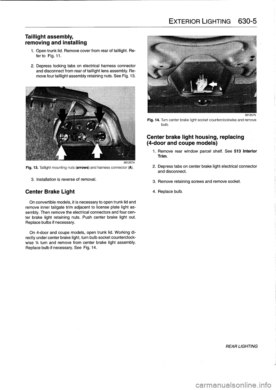
Taillight
assembly,
removing
and
installing
1
.
Open
trunk
lid
.
Remove
cover
from
rear
of
taillight
.
Re-
fer
to
Fig
.
11
.
2
.
Depress
locking
tabs
on
electrical
harness
convector
and
disconnect
from
rear
of
taillight
lens
assembly
.
Re-
move
four
taillight
assembly
retaining
nuts
.
See
Fig
.
13
.
0012574
Fig
.
13
.
Taillight
mounting
nuts
(arrows)
and
harness
connector
(A)
.
3
.
Installation
is
reverse
of
removal
.
Center
Brake
Light
On
convertible
models,
it
is
necessary
to
open
trunk
lid
and
remove
inner
tailgatetrim
adjacent
to
license
plate
light
as-
sembly
.
Then
remove
the
electrical
connectors
and
four
cen-
ter
brake
light
retaining
nuts
.
Push
center
brake
light
out
.
Replace
bulbs
if
necessary
.
On
4-door
and
coupe
models,
open
trunk
lid
.
Working
di-
rectly
under
center
brake
light,
turn
bulb
socket
counterclock-
wise
1
/4turn
andremove
from
center
brake
light
assembly
.
Replace
bulb
if
necessary
.
See
Fig
.
14
.
EXTERIOR
LIGHTING
630-
5
0012575
Fig
.
14
.
Turncenter
brake
light
socket
counterclockwise
and
remove
bulb
.
Center
brake
light
housing,
replacing
(4-door
andcoupe
models)
1
.
Remove
rear
window
parcel
shelf
.
See513
Interior
Trim
.
2
.
Depress
tabs
on
center
brake
light
electrical
connector
and
disconnect
.
3
.
Remove
retaining
screws
and
remove
socket
.
4
.
Replace
bulb
.
REAR
LIGHTING
Page 446 of 759
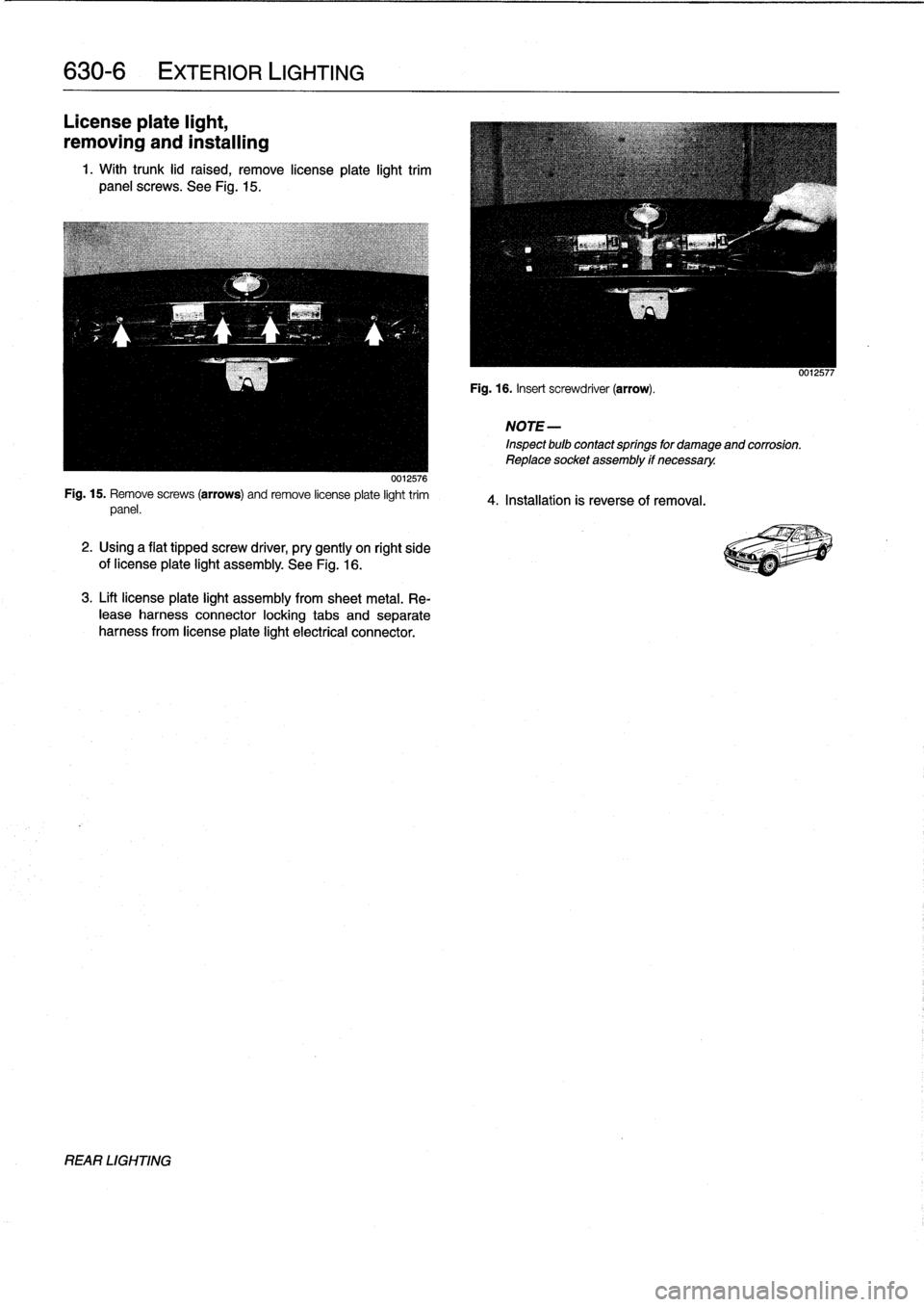
630-
6
EXTERIOR
LIGHTING
License
plate
light,
removing
and
installing
1
.
With
trunk
lid
raised,
remove
lícense
plate
light
trim
panel
screws
.
See
Fig
.
15
.
0012576
Fig
.
15
.
Remove
screws
(arrows)
and
remove
license
plate
light
trim
panel
.
2
.
Using
a
flat
tipped
screw
driver,
pry
gently
on
right
side
of
license
plate
light
assembly
.
See
Fig
.
16
.
3
.
Lift
license
plate
light
assembly
from
sheetmetal
.
Re-
lease
harness
connector
locking
tabs
and
separate
harness
from
license
plate
light
electrical
connector
.
REAR
LIGHTING
Fig
.
16
.
Insert
screwdriver
(arrow)
.
NOTE
-
Inspect
bulb
contactsprings
for
damageand
corrosión
.
Reptace
socket
assembly
if
necessary
.
4
.
Installatíon
is
reverse
of
removal
.
0012577
Page 469 of 759
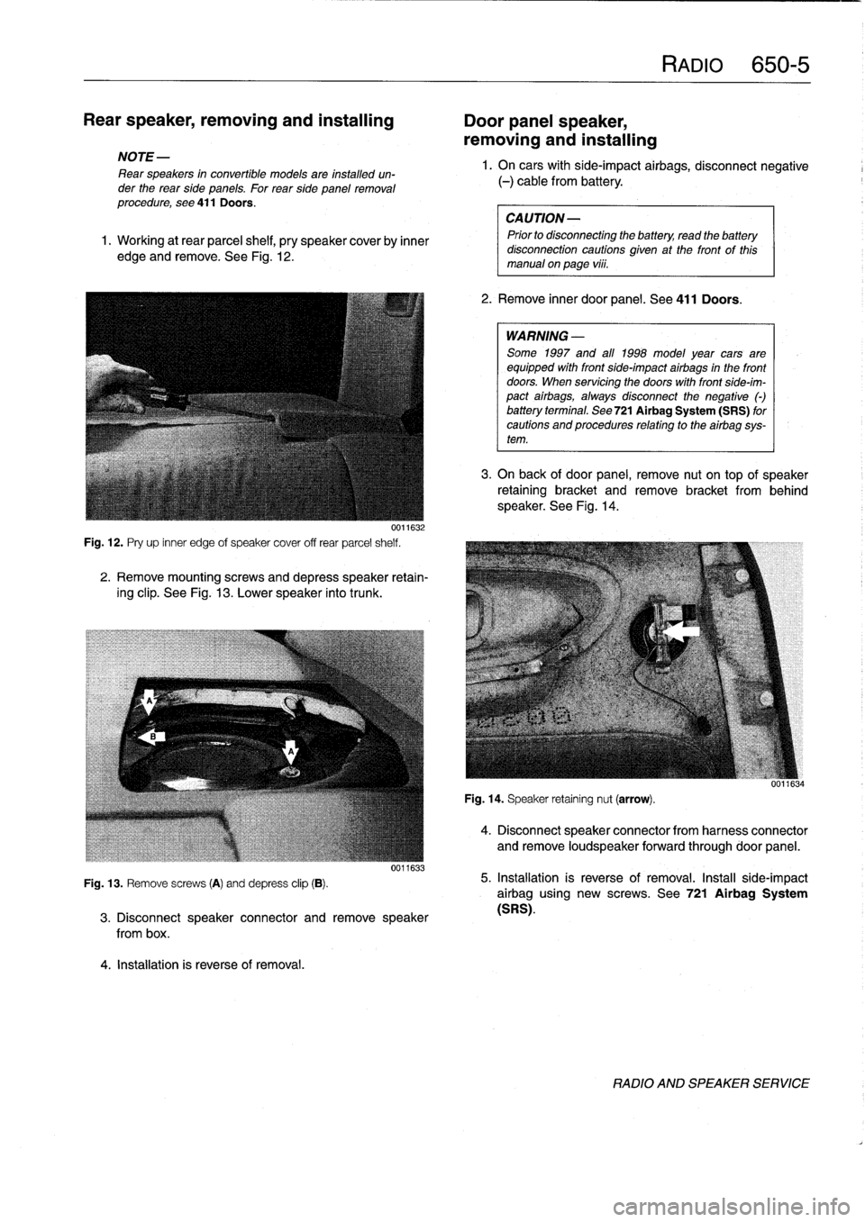
Rear
speaker,
removing
and
installing
Door
panel
speaker,
removing
and
installing
NOTE
-
Rear
speakers
in
convertible
models
are
installed
un-
der
the
rear
side
panels
.
For
rearside
panelremoval
procedure,
see
411Doors
.
1
.
Working
at
rear
parcel
shelf,
pry
speakercoverby
inner
edge
and
remove
.
See
Fig
.
12
.
0011632
Fig
.
12
.
Pry
up
inner
edge
of
speaker
cover
off
rear
parcel
shelf
.
2
.
Remove
mountingscrews
and
depress
speaker
retain-
ing
clip
.
See
Fig
.
13
.
Lower
speaker
into
trunk
.
Fig
.
13
.
Remove
screws
(A)
and
depress
clip
(B)
.
4
.
Installation
is
reverse
of
removal
.
0011633
3
.
Disconnect
speaker
connector
andremove
speaker
from
box
.
RAM
650-5
1.
On
carswith
side-impact
airbags,
disconnect
negative
(-)
cable
from
battery
.
CAUTION-
Prior
to
disconnecttog
the
battery,
read
the
battery
disconnection
cautions
given
at
the
front
of
this
manual
on
page
vi¡¡
.
2
.
Remove
inner
door
panel
.
See
411
Doors
.
WARNING
-
Some
1997
and
all
1998
model
year
cars
are
equipped
with
front
side-impact
airbags
in
the
front
doors
.
When
servicing
the
doors
with
front
side-im-
pact
airbags,
alwaysdisconnect
the
negative
()
battery
terminal
.
See
721Airbag
System
(SRS)
for
cautions
and
procedures
relating
to
theairbag
sys-
tem
.
3
.
On
back
of
door
panel,
remove
nut
on
top
of
speaker
retaining
bracket
and
remove
bracket
from
behind
speaker
.
See
Fig
.
14
.
Fig
.
14
.
Speaker
retaining
nut
(arrow)
.
4
.
Disconnect
speaker
connector
from
harness
connector
and
remove
loudspeaker
forwardthrough
door
panel
.
5
.
Installation
is
reverse
of
removal
.
Install
side-impact
airbag
using
new
screws
.
See
721
Airbag
System
(SRS)
.
RADIO
AND
SPEAKER
SERVICE
Page 486 of 759
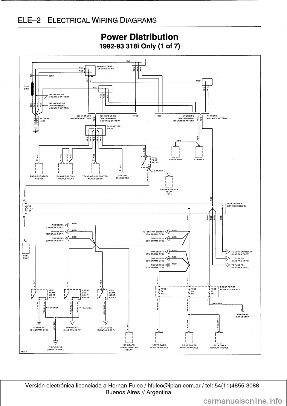
ELE--2
ELECTRICAL
WIRING
DIAGRAMS
FUSE
LINK
64766
I-i
I
-
i
a
1
I
_
ZJ
I
I
I
I
I
I.
4
2
GRN/VIO
I_I
!
___I
I_I
1
D>
6
END
INECONTROL
ENGINECONTROL
TRANSMISSION
CONTROL
DATALINK
MODULE
MODULE
RELAY
MODULE
(EGS)
CONNECTOR
I
I
I
I
5
(F18
--_______________________________________________
O19~
N
RIBUON
BOX
I
FUSE
II
15A
o~___________________________________________________Q~____-aft
TO
FUSE
F5
C
RED
(DIAGRAM
6
OF
7)
FUELPUMP
I
(DIAGRAM60F7)
C'
RED
\
L------r>
(DIAGRAM60F7)
I
LOW
F
I
FRONT
HIGH
BEAM
FOGJ
BEAM
I
I
LIGHT
I
I
LIGHT
I
j
/
I
LIGHT
RELAY
I
RELAY
li
SJ
RELAY
1992
1993W/TRUNK
MOUNTEDBATTERV
1993W/ENGINE
COMPARTMENTMOUNTEDBATTERV
1993W/TRUNK
1993W/ENGINE
1992
1992
WI
ENGINE
W/TRUNK
BATTERY
MOUNTEDBATTERV
¢)
MOUNTED
BATTERY
MOUN
O
TEDBATT
I
ERV
¢I¢I
MOUNTEDBATTERV
TOFUSEF40
<
,.k
RED
(DIAGRAM
6
OF
7)
I
I
(DIAGRAM
3
OF
7)
TO
FUSEF3
E
RED
(DIAGRAMfiOF7)
"
.
1k
I
(DIAGRAM
6OF7)
>I
mJ~CANADA
RED
BNUMPSTART
JUNCTION
POINT
REO
Power
Distribution
1992-93
318i
Only
(1
of
7)
-UNCTION
POINT
TOFUSEF15
TO
FUSE
F29
(DIAGRAM60F7)
(OIAGRAM6OF7)
I
~1
.
FUEL
_I
I
_I
~
(PUMP
GENERATOR
STARTER
I
,(
I
RELAY
TO
IGNITION
SWITCH
QA
TOFUSE
F20
TOFUSEF19
FRED
(DIAGRAM6OF7)
`
I
III
-
(DIAGRAM70F7)
OXVGENSENSOR
RELAY
(4CVL)
RED
RED
RED
ON-BOARD
LEFTPOWERRIGHTPOWERLEFTPOWER
TOFUSEF17
COMPUTERHORN
WINDOWMODULE
WINDOWMODULE
WINDOW
MODULE
(DIAGRAM
60F
7)
RELAY
TO
COMFORTRELAV
Page 490 of 759
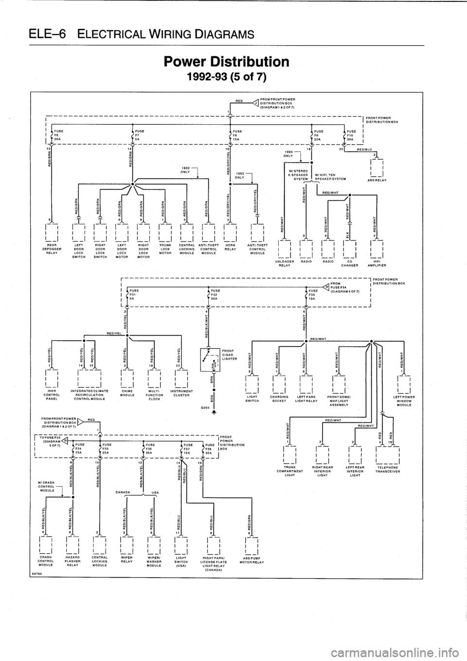
CALWIRING
DIAGF
Power
Di
:
1992-93
RED
FROMFRONTPOWER
DISTRIBUTION
BOX
(DIAGRAM
1
620F7)
1
FRONTPOWER
DISTRIBUTION
BOX
i
I
I
1592
II
ONLY
WI
STEREO
-
I
ONLY
6-
SVS
SPEAKER
I
W/HIFI,TEN
I
TE~~PEAKERSYSTEM
ASSRELAY
3
RED/WHT
O
t7
0
t7
3
6
6
8
1
3
¢
3
F
~
~
3
a
a
o
I
I
I
II
I
I
I
I
I
I
I
I
I
I
I
I
I
i
I
¢
5
s
z
I
REAR
I
I
LEFT
I
I
RIGHT
I
I
LEFT
I
I
RIGHT
I
I
TRUNK
I
CENT
RA
I
L
ANTI-THEFT
I
HORN
I
ANTI-THEFT
I
I
I
I
I
I
I
I
I
I
DEFOGGERDOOR
DOOR
DOORDOOR
LOCK
LOCKING
CONTROL
RELAY
CONTROL
II
I
IIIIIII
RELAY
LOCK
LOCKLOCKLOCK
MOTOR
MODULEMODULE
MODULE
I
_
II
-
II
_
II
-
II
_
I
SWITCHSWITCH
MOTORMOTOR
UNLOADER
RADIO
RADIO
CD
HIF'
RELAY
CHANGER
AMPLIFIER
r________________________________________________-FRONT
POWER
I
FROM
I
DISTRIBUTION
BOXR
FUSE
I
FUSE
FUSE
FUSE
(DIAGRAMSOF7)
I
F31
F32
F33
II
5A
30A
I,0
OA
I
L
-----
______
.......
.
.
.
.
.
.
.
.
.
..
________J
z
4
6
3
3
a
"
"
REDIYEL
RED/WHT
"
FRONT
Y
CIGAR
I
LIGHTED
3
3
3
3
3
3
1
-
19
15
3
-
18
-
22
-
I
_
_I
I
I
iI
(
I
II
5
1
s
s
1
I
I
I
I
II
I
I
II
~
(-
I
I
I
I
-
I
II
IiI
_I
!
___I
!
_I
!
_I
i
-I_
I
I
I
I
I
I
I
I
I
I
I"
KIM
INTEGRATED
CLIMATE
CHIME
MULTI-
INSTRUMENT
"
I
_I
I
-
I
I
~I
I
-I
I
_I
CONTROL
RECIRCULATION
MODULE
FUNCTION
CLUSTER
LIGHT
CHARGING
LEFTPAPK
FRONT
DOME/
LEFT
POW
PANEL
CONTROLMODULE
CLOCK
SWITCH
SOCKET
LIGHTRELAV
MAP
LIGHT
WINDON
ASSEMBLY
MODULE
G203
1
FROMFRONTPOWER
RED
RED/WHT
DISTRIBUTION
BOX
(DIAGRAM
1
82OF7)
RED/WIT
3
TFUSEF33
FRONT
ODAORAM
R
______
__________________-
I
POWER
¢
1
2
2
416
I
SOFT)
FUSE
FUSE
FUSE
FUSE
FUSEFUSE
(DISTRIBUTION
F34
136
F37
F38
BOX
I
I
II
III
I
z'235
A-____
t0A
-
30=~
IIIII11I
10
1z
14Es
TRUNK
RIGHTREAR
LEFTREAR
TELEPHONE
COMPARTMENT
INTERIOR
INTERIOR
TRANSCEIVER
LIGHT
LIGHTLIGHT
P
W1
C
RASH
CONTROL
MODULE
CANADAUSA
fl
6
2
2
8
11
8
0
I
I
I
I
I
I
I
I
I
I
I
I
I
I
I
II
I
I
I
I
I
I
I
I
I
I
I
I
I
I
I
CRASH
HAZARD
CENTRAL
WIPER
WIPER/
LIGHT
RIGHTPARK/
ABSPUMP
CONTROLFLASHER
LOCKING
RELAY
WASHER
SWITCH
LICENSEPLATE
MOTORRELAV
MODULE
RELAY
MODULE
MODULE
(USA)
LIGHTRELAV
(CANADA)
64784
Page 493 of 759
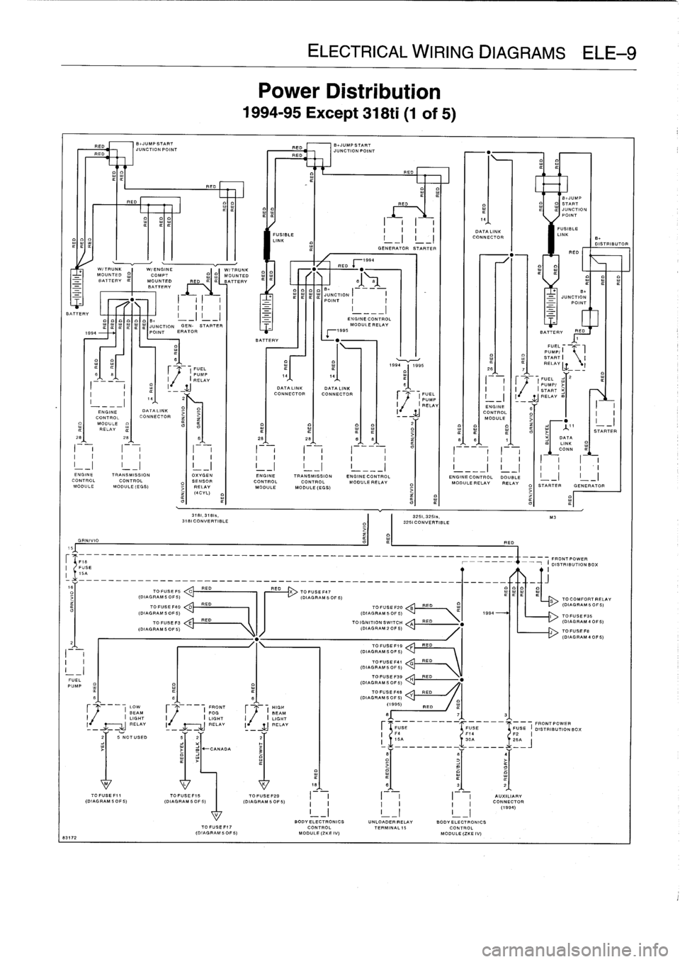
ELE
Power
E
1994-95
Exc
JMPSTART
B+JUMP
START
C710NPOINT
RED
JUNC710NPOIN7
RED
REO
.,
.
..
Fil
-----------
FUSIBLE
I
-
I
I
-I
CONNECTOR
I
LINK
B
LINK
m
D
¢
GENERATOR
STARTER
RED
x1994
W/TRUNK
W/ENGINE
W/TRUNK
RED
+
.
-
MOUNTED
MOUNTED
I~
BATTERY
MOUNTED
RED
BATTERY
61
81
w
_¢
BATTERY
o
B+
.
.'S
.
JS
_
JUONCINT
TION
I
I
B+_
I
I
I
P
I
I
-
JUNCTION
_
POINT
BATTERY
I
II
-
-_-
I
-
0
ENGINECON7ROL
¢
JUNCTION
GEN-
STARTER
MODULERELAY
1994
POINT
ERATOR
x1995
BATTERY
REO
Iffm
BATTERY
+
"
1
o
FUEL'w
PUMP/
I
B
w
w
START
I
I
mm
O
0
~
~
Y
¢¢ww
r'
19941995
RELAY
¢
Lz
(
PUMP
2
2fi
7
¢
¢
I
R
r
ELAY
14
14
r
2
'
8
I
1
(
P/
M
i
II
w
-
yJ
DATA
LINK
DATA
LINK
I
I
I~
SPT
U
ART
I
CONNECTOR
CONNECTOR
FUEL
I
I
14
22
PUMP
-_I
_--
IJRELAYm
_--I
O
I
RELAY
ENGINE
I
ENGINE
DATALINK
CONTROLCONTROL
CONNECTOR
-
MODULEj
MODULE
2
RELAY
-
S'
28
B
28
28
BB
86
1
DATA
LI
NK
II
I2
I
I
I
I
I
I
_
__
__
__
m
C.
NN
I
I
I
I
I
I
I
I
I
I
I
I
I
I
I
¢
I__I
I__I
!
_I
!
_I
!
_I
!
___I
!
___I
!
_I
I
I
ENGINETRANSMISSION
OXYGEN
ENGINE
TRANSMISSION
ENGINECONTROL
ENGINECONTROL
DOUBLE
CONTROL
CONTROL
SENSOR
CONTROL
CONTROL
MODULERELAY
MODULE
BELAY
RELAY
MODULE
MODULE
(EGB)
RELAY
MODULE
MODULE(EGS)
O
STARTER
GENERAT
(4CYL)
3181,37815,
3251,3251
.,
M3
3181
CONVERTIBLE
3251
CONVERTIBLE
GRN/VIO
RED
15
P1B
FRONT
POWER
USE
-1
I
DISTRIBUTION
BOX
-
-
-
---
--
-
---
-
-
-
-
-
-
-
-
-
---
--
-
---
-
---
-
-
-
-
-
-
-
-
-
-
-
-
----
-
-
-
-
-
-
-
-
-----
---
g
TO
FUSE
15
C
RED
RED
X
TO
FUSEF47
-
1.20
(DIAGRAM50F5)
(DIAGRAMSOF5)
S
TOCOMFORTR
TO
FUSEF40
0
RED
TO
TUBEF20
B
RED
(DIAGRAMSOF
(D(AGRAM
5
0F
5)
(DIAGRAM
5
0F
5)
R
1994
I
TO
'
.BE
P
.1
70
FUSE
F3
E
RED
TO
IGNITION
SWITCH
A
RED
"
(DIAGSAM4OF
(DIAGRAM5OF5)
ID
IAGRAM2OF5)
J
70
FUSE
FB
(DIAG
RAM
4
OF
2
TO
FUSEFI9
F
RED
I
I
(DIAGRAMSOF5)
I
I
TO
FUSE-
G
RED
I
-
I
(DIAGRAMSORS)
TOFUSEF39
RED
FUEL
PUMP
(DIAGRAMSOFS)
H
fi
6
g
(DIAGRAMSOFSTOFUSE
'48
I
Y
RED
(1
O
I
FRONT
HIGH
99
5)
RED
¢BEAM
FOG
I
BEAM
8
7
3
(
LIGHT
I
(
LIGHT
I
(
LIGHT
RELAY
I
j~(
RELAY
I~
~j
RELAY
r
FUBE
FUSE
FUSE
I
FRONTPOWER
OISTRIBUTIONBCX
2
I
F4
14
F25
NOTUSED
5
2
2
5
S
2
_
CANADA
3
v
8
B
4
M
L
K
18
8
3
2
TOFUSEF11
TOFUSEFIS
TOFUSEF29
I
I
I
I
AUXILIARY
(OIAGRAMSOFS)
(DIAGRAM
5DF5/
(DIAGRAM
SOBS)
I
I
I
I
I
I
CONNECTOR
V
I
_I
_
I
-I
(19)
BODY
ELECTRONICS
UNLO
I
ADERRELAY
BODY
EI
LCTRDNCS
TOFUSEFI7
CONTROL
TERMINAL15
CONTROL
IDIAGRAM50F5(
MODUL
.(ZKEIV)
MODULE(ZKEIV)
83172
-