Freeze BMW 318i 1997 E36 Workshop Manual
[x] Cancel search | Manufacturer: BMW, Model Year: 1997, Model line: 318i, Model: BMW 318i 1997 E36Pages: 759
Page 20 of 759
010-12
FUNDAMENTALSFOR
THE
DO-IT
YOURSELF
OWNER
Jump
Starting
Car
Cars
with
discharged
or
dead
batteries
can
be
jump-started
using
the
good
battery
from
another
car
.
When
jump-starting
the
engine,
always
note
the
following
warnings
.
WARNING
-
"
Battery
acid
(electrolyte)
can
cause
severe
burns,
and
will
damage
the
car
and
clothing
.
lf
electrolyte
is
spilled,
wash
the
surface
with
large
quantities
of
water
.
lfit
gets
finto
eyes,
flush
them
with
water
for
severa¡
minutes
and
cal¡
a
doctor
.
"
Batteries
produce
explosive
and
noxious
gas-
ses
.
Keep
sparks
and
flames
away
.
Do
not
smoke
near
batteries
.
"
Do
not
jump-start
the
engine
if
you
suspect
that
the
battery
is
frozen
.
Trapped
gas
may
explode
.
Allow
the
battery
to
thaw
first
.
"
Do
not
quick-charge
the
battery
(for
boost
start-
ing)for
longer
than
one
minute,
and
donot
ex-
ceed
15
volts
at
the
battery
with
the
boosting
cables
attached
.
Wait
at
least
one
minutebefore
boosting
the
battery
a
second
time
.
"
Some
electrical
system
'comfort"
features
may
not
function
correctly
once
battery
power
is
restored
.
For
example,
the
front
window
one-touch-up
func-
tion
may
be
disabled
.
Some
electrical
systems
will
need
to
be
reinitialized
Consult
the
appropriate
re-
pairgroup
formore
specific
information
.
1
.
Place
cars
close
together,
but
do
not
allow
them
to'touch
each
other
.
Turn
off
the
engine
of
thecar
with
the
good
battery
.
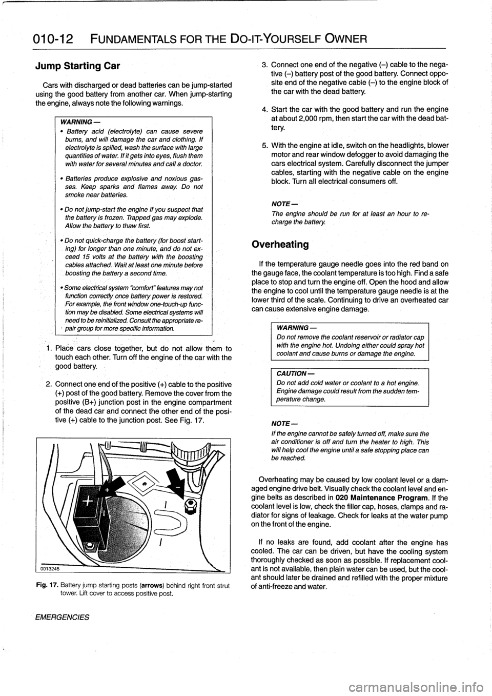
2
.
Connect
oneend
of
the
positive
(+)
cable
to
the
positive
(+)
post
of
the
good
battery
.
Remove
the
coverfromthe
positive
(B+)
junction
post
in
the
engine
compartment
of
the
dead
car
and
connect
the
other
end
of
the
posi-
tive
(+)
cable
to
the
junction
post
.
See
Fig
.
17
.
EMERGENCIES
3
.
Connect
one
end
of
the
negative
(-)
cable
to
the
nega-
tive
(-)
battery
post
of
the
good
battery
.
Connect
oppo-
site
end
of
the
negative
cable
(-)
to
the
engine
block
of
thecar
with
the
dead
battery
.
4
.
Start
thecar
with
the
good
battery
and
runthe
engine
at
about2,000
rpm,
then
start
the
car
with
the
dead
bat-
tery
.
5
.
With
the
engine
at
¡dle,
switch
on
the
headlights,
blower
motor
and
rear
window
defogger
to
avoid
damaging
the
cars
electrical
system
.
Carefully
disconnect
the
jumper
cables,
starting
with
the
negative
cable
on
the
engine
block
.
Turn
all
electrical
consumers
off
.
NOTE-
The
engineshould
be
run
for
at
least
an
hour
to
re-
charge
the
battery
.
Overheating
lf
the
temperature
gauge
needle
goes
into
the
red
band
on
the
gauge
face,
the
coolant
temperature
is
too
high
.
Find
a
safe
place
to
stop
and
turn
the
engine
off
.
Open
the
hood
and
allow
the
engine
to
cool
until
the
temperature
gauge
needle
is
at
the
lower
thirdof
the
scale
.
Continuing
to
drive
an
overheated
car
can
cause
extensive
engine
damage
.
WARNING
-
Do
not
remove
the
coolant
reservoir
or
radíator
cap
with
the
engine
hot
.
Undoing
either
couldspray
hot
coolant
and
cause
burns
or
damage
the
engine
.
CAUTION-
Do
not
add
cold
water
or
coolant
to
a
hot
engine
.
Engine
damage
could
result
from
the
sudden
tem-
perature
change
.
NOTE-
If
the
enginecannot
be
safely
tumed
off,
make
sure
the
air
condifioner
isoff
and
turn
the
heater
to
high
.
This
will
helo
cool
the
engine
until
a
salestopping
place
canbe
reached
.
Overheating
may
be
caused
bylow
coolant
leve¡
or
a
dam-aged
engine
drive
belt
.
Visually
check
the
coolant
leve¡
and
en-
gine
belts
as
described
in
020
Maintenance
Program
.
lf
the
coolant
leve¡
is
low,
check
the
filler
cap,hoses,
clamps
and
ra-
diator
for
signs
of
leakage
.
Check
for
leaks
at
the
water
pump
on
the
frontof
theengine
.
lf
no
leaks
are
found,
add
coolant
after
the
engine
has
cooled
.
The
carcan
be
driven,
but
have
the
cooling
system
thoroughly
checked
assoonas
possible
.
lf
replacement
cool
0013245
-
ant
is
not
available,
then
plain
water
canbe
used,
butthe
cool-
antshould
later
be
drained
and
refilled
with
theproper
mixture
Fig
.
17
.
Battery
jump
starting
posts
(arrows)
behind
right
frontstrut
of
anti-freeze
and
water
.
tower
.
Lift
cover
to
access
positive
post
.
Page 22 of 759
010-14
FUNDAMENTALS
FOR
THE
DO-ITYOURSELF
OWNER
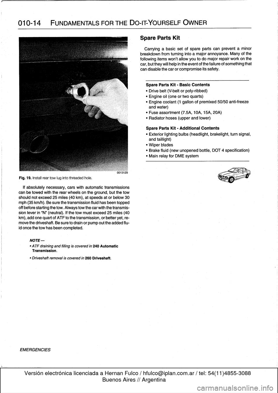
Fig
.
19
.
Instaf
rear
tow
lug
into
threaded
hole
.
if
absolutely
necessary,
cars
with
automatic
transmissions
can
be
towed
with
the
rear
wheels
on
the
ground,
butthe
tow
should
not
exceed
25
miles
(40
km),at
speeds
at
or
below30
mph
(35
km/h)
.
Be
sure
the
transmission
fluid
hasbeen
topped
off
before
starting
the
tow
.
Always
tow
thecar
with
the
transmis-
sion
lever
in
"N"
(neutral)
.
If
the
tow
must
exceed25
miles
(40
km),
add
one
quart
of
ATF
to
the
transmission,
or
better
yet,
re-
move
the
driveshaft
.
Be
sure
to
drain
or
pump
outthe
added
flu-
id
once
the
tow
has
been
completed
.
NOTE-
"
ATF
draining
and
filling
is
covered
in
240
Automatic
Transmission
.
"
Driveshaft
removal
is
covered
in
260
Driveshaft
.
EMERGENCIES
úo1W¿b
Spare
Parts
Kit
Carrying
a
basic
set
of
spare
parts
can
prevent
a
minor
breakdown
from
turning
into
a
major
annoyance
.
Many
of
the
following
itemswon't
allow
you
todo
major
repair
workon
the
car,
but
they
will
help
in
the
event
of
the
failure
of
something
that
can
disable
thecar
or
compromise
its
safety
.
Spare
Parts
Kit
-
Basic
Contents
"
Drive
belt
(V-belt
or
poly-ribbed)
"
Engine
oil
(one
or
two
quarts)
"
Engine
coolant
(1
gallonof
premixed
50/50
anti-freeze
and
water)
"
Fuse
assortment
(7
.5A,
10A,
15A,
20A)
"
Radiator
hoses
(upper
and
lower)
Spare
Parts
Kit
-
Additional
Contents
"
Exterior
lighting
bulbs
(headlight,
brakelight,
turn
signal,
and
taillight)
"
Wiper
biades
"
Brake
fluid
(new
unopened
bottle,
DOT
4
specification)
"
Main
relay
for
DME
system
Page 23 of 759
020
Maintenance
Program
GENERAL
.
.
...
.
.
.
...
.
.
.
.
.
.
.
.
.
.
.
...
.
..
020-2
BMW
Service
Indicator
......
..
....
..
...
..
.
020-2
Oil
Service
.....
.
..........
..
...
...
...
..
.
020-2
Inspection
I
and
Inspection
II
.
..
....
..
...
..
.
020-2
Resetting
Service
Indicator
....
.
....
..
...
..
.
020-3
MAINTENANCE
TABLES
..
.
.
.
.
.
........
020-3
FLUID
AND
LUBRICANT
SPECIFICATIONS
.
.
.
.
.
.
.
...
.
.
.
....
.
...
020-8
Manual
Transmission
Fluid
..
.
.
.
.
.
....
.
.
.
.
020-8
Automatic
Transmission
Fluid
.
.
.
.
.
....
.
.
.
.
020-8
Final
Drive
Gear
Oil
................
.
.
.
.
020-9
Brake
Fluid
.
.
.
.
.
................
.
.
.
.
020-9
Engine
Coolant
(Anti-freeze)
.
.
...
.
....
.
.
.
.
020-9
Power
Steering
Fluid
........
..
......
.
.
.
.
020-9
ENGINE
OIL
SERVICE
.
.
...
.
.
.
...
.
.
.
.
.
.
020-9
Engine
oil,
checking
leve¡
..
...
...
..
........
020-9
Engine
oil
and
filter,
changing
....
.
......
.
..
020-9
ENGINE
COMPARTMENT
MAINTENANCE
...
.
.
.
.
.
.
.
.
.
.
.
.
.
......
020-10
Air
filter,
replacing
.
...
...
.
.....
.
.....
.
...
020-11
Spark
plugs,
replacing
...
.
......
.
...
..
...
020-11
¡dle
Speed
.
..
...
...
....
.
......
.
...
..
...
020-12
Battery,
checking
and
cleaning
.......
..
...
020-12
Battery,
replacing
.
.....
.
.....
.
.....
..
...
020-12
Accelerator
and
Throttle
Linkage
.
.....
..
...
020-13
Engine
DriveBelts
.....
.
....
..
...
...
...
.
020-13
V-belt,
replacing
(4-cylinder
engines
built
up
to
1/94)
..
....
.
020-13
Poly-ribbed
belt,
replacing
(4-cylinder
engines
built
from
1194
and
all
6-cylinder
engines)
.
.
....
..
......
020-13
Cooling
System
Service
.
...
..
....
..
....
..
020-14
Power
steering
fluid,
checking
leve¡
.
..
....
.
.
020-14
Oxygen
Sensors
....
...
..
..
....
.
.....
.
.
020-15
MAINTENANCE
PROGRAM
020-1
UNDER-CAR
MAINTENANCE
.
..
.
...
.
.
.020-16
'
Fuel
filter,
replacing
...
.
.....
..
.....
..
..
.020-16
Tires,
checking
inflation
pressure
.
.....
.
....
020-17
Tires,
rotating
...
..
.....
..
....
..
....
.
....
020-17
Wheels,
aligning
..
.....
.
...........
.
....
'020-17
Brake
system,
inspecting
.
.
....
.
.....
..
...
020-17
Brake
pad/rotor
wear,checking
.
......
.
....
020-17
Brake
fluid,
replacing
.........
..
.
..
..
.
020-17
Parking
brake,
checking
......
.
.....
..
....
020-17
Exhaust
system,
inspecting
....
..
.....
.
...
.020-18
Manual
Transmission
Senrice
..
..
.....
.
....
020-18
Manual
transmission
fluida
checking
and
filling
..
.
....
..
.
.
..
..
....
020-18
AutomaticTransmission
Service
.
....
...
....
020-18
Front
suspension
and
steeringlinkages,
inspecting
..
.
:.....
.
....
..
.....
..
...
.
.020-18
Rear
suspension,
inspecting
.
..
...
...
....
..
020-18
Final
drive
oil
leve¡,
checking
.
.
.
...
....
...
..
020-18
Fuel
tank
and
fuel
lines,
inspecting
.
.....
....
020-19
Clutch
fluid,
checking
...
...
...
...
....
.....
020-19
Drive
axle
joint
boots,
inspecting
...
..
.....
..
020-19
BODY
AND
INTERIOR
MAINTENANCE
.
.
.
.
.
.
.
.
.
.
.
.
.
.
.
.
.
.
...
.
.020-19
Windshield
Wiper
Blade
Maintenance
....
.
.
020-19
Body
and
hinges,
lubricating
.
.....
..
......
.
020-19
Seat
Belts
...
..
...
...
...
..
.....
..
.....
.
.
020-20
Exterior
Washing
..
...
...
..
.
.
...
..
......
.020-20
Waxing
.....
..
...
...
...
..
.....
..
.......
020-20
Polishing
..
...
...
...
....
..
..........
..
.
.'020-20
Washing
Chassis
.
...
....
.
....
..
.....
.
...
020-20
Special
Cleaning
.
.
.....
..
...
.
.....
..
..
.020-20
Interior
Care
.
....
..
....
..
..
.
.
......
.
...
020-20
Leather
Upholstery
and
Trim
...
..
....
...
...
020-20
TABLES
a
.
Oil
Service
......
...
.
..
.............
...
---
020-4
b
.
Inspection
1
Service
..
.
.
.............
....
...
020-5
c
.
Inspection
11
Service
.
.
...
...........
..
.
..
..
020-6
d
.
Scheduled
Maintenance-Time/Mileage
Intervals
..
020-7
e
.
Fluids
and
Lubricants
..
...
...........
.....
..
020-8
Page 27 of 759
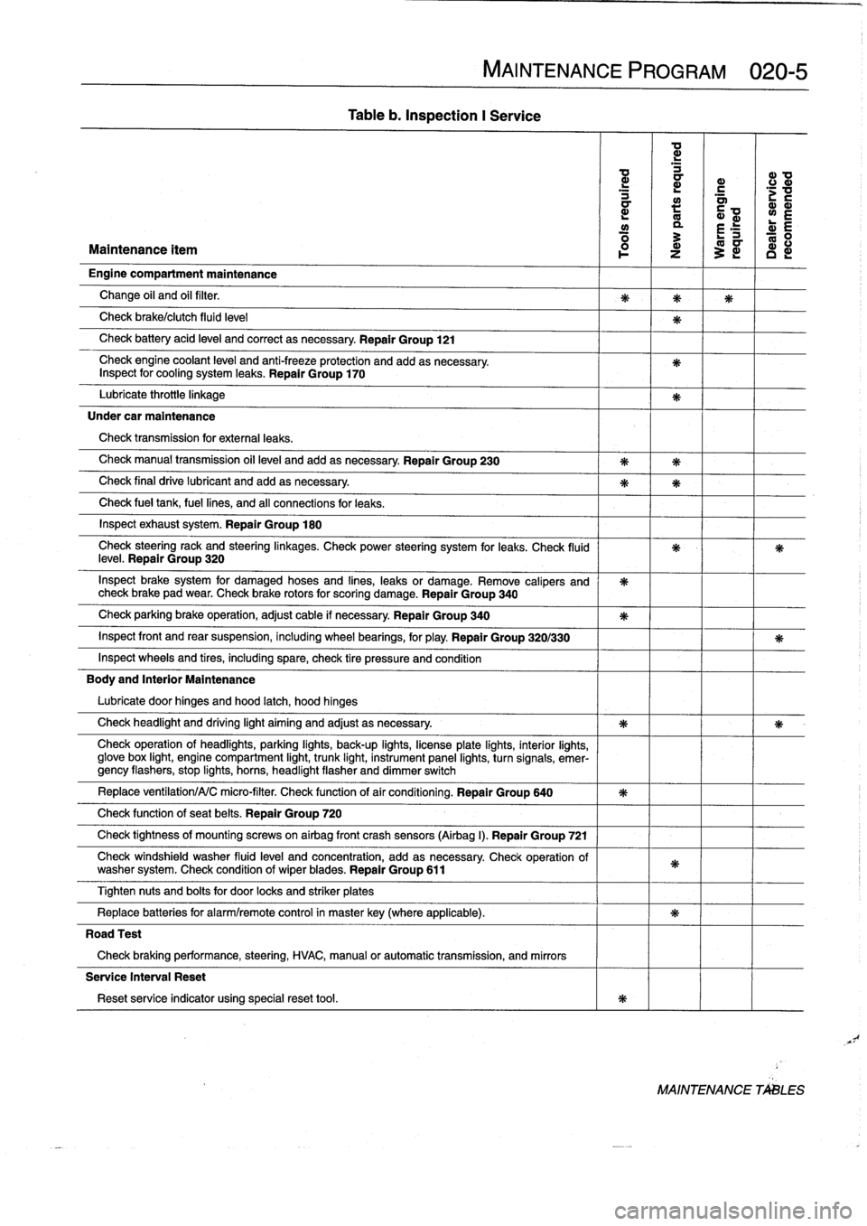
Table
b
.
Inspection
I
Service
MAINTENANCE
PROGRAM
020-5
ad
d
d
ID
a
r
c
d
a~
;v
a
:
Q~
wE
y
a
r
E
R
:
L-
0
Maintenance
ítem
1
z
3
~
c
d
Engine
compartment
maintenance
Change
oil
and
oil
filter
.
Check
brake/clutch
fluid
leve¡
Check
battery
acid
leve¡
and
correct
asnecessary
.
Repair
Group
121
Check
engine
coolant
level
and
anti-freeze
protection
and
addasnecessary
.
Inspect
for
cooling
system
leaks
.
Repair
Group
170
Lubricate
throttie
linkage
Under
car
maintenance
Check
transmission
for
externa¡
leaks
.
Check
manual
transmission
oil
leve¡
andadd
asnecessary
.
Repair
Group
230
Check
final
drive
lubricant
and
addasnecessary
.
Check
fue¡
tank,
fuel
lines,
and
all
connections
for
leaks
.
Inspect
exhaust
system
.
Repair
Group
180
Check
steeringrack
and
steeringlinkages
.
Check
power
steering
system
for
leaks
.
Check
(luid
leve¡
.
Repair
Group
320
Inspect
brake
system
for
damaged
hoses
and
fines,
leaks
or
damage
.
Remove
calipers
and
check
brake
pad
wear
.
Check
brake
rotors
for
scoring
damage
.
Repair
Group
340
Check
parking
brake
operation,
adjust
cable
if
necessary
Repair
Group
340
Inspect
front
and
rear
suspension,
including
wheel
bearings,
for
play
.
Repair
Group
320/330
Inspect
wheelsand
tires,
including
spare,
check
tire
pressure
and
condition
Body
and
Interior
Maintenance
Lubricate
door
hinges
and
hood
latch,
hood
hinges
Check
headlight
and
driving
light
aiming
and
adjust
as
necessary
.
Check
operation
of
headlights,
parking
lights,
back-up
fights,
licenseplate
lights,
interior
lights,
glove
box
light,
engine
compartment
light,
trunk
light,
instrument
panel
lights,
turnsignals,
emer-gency
flashers,
stop
fights,
horas,
headlight
flasher
and
dimmer
switch
Replace
ventilation/A/C
micro-filter
.
Check
functionof
air
conditioning
.
Repair
Group
640
Check
function
of
seat
belts
.
Repair
Group
720
Check
tightness
of
mountfng
screws
on
airbag
front
crash
sensors
(Airbag
I)
.
Repair
Group
721
Check
windshield
washer
fluid
leve¡
and
concentration,
add
as
necessary
Check
operation
of
washer
system
.
Check
condition
of
wiperblades
.
Repair
Group
611
Tighten
nuts
and
bolts
for
door
locks
and
striker
plates
Replace
batteries
for
alarm/remote
control
in
masterkey(where
applicable)
.
Road
Test
Check
braking
performance,
steering,
HVAC,
manual
or
automatic
transmission,
and
mirrors
Service
Interval
Reset
Reset
service
indicator
using
specialreset
tool
.
MAINTENANCE
TALES
Page 28 of 759
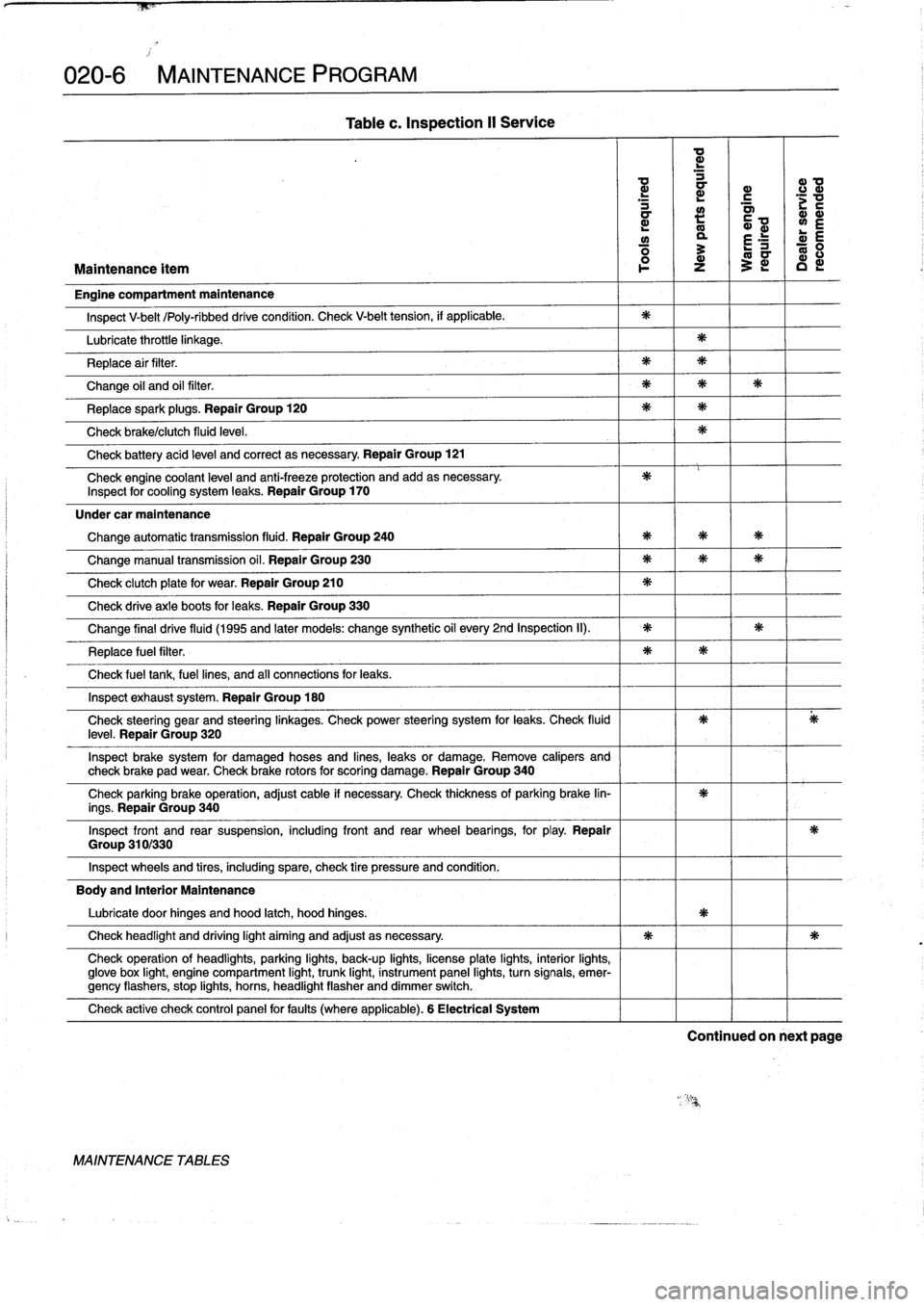
020-6
MAINTENANCE
PROGRAM
Group
310/330
Table
c
.
Inspection
II
Service
a
d
d
a
a>
0
d
a
r
.c
mm
L
m
y
L
E
ó
3
E
ó
Maintenance
ítem
l
o-
z
~
c
Engine
compartment
maintenance
Inspect
V-belt
/Poly-ribbeddrive
condition
.
Check
V-belt
tension,
if
applicable
.
Lubricate
throttle
linkage
.
Replace
air
filter
.
Change
oil
and
oil
filter
.
Replacespark
plugs
.
Repair
Group
120
Check
brake/clutch
fluid
leve¡
.
Check
battery
acid
leve¡
and
correct
asnecessary
.
Repair
Group
121
Check
engine
coolant
leve¡
and
anti-freeze
protection
and
add
asnecessary
.
Inspect
for
cooling
system
leaks
.
Repair
Group
170
Under
car
maintenance
Change
automatic
transmission
fluid
.
Repair
Group
240
Change
manual
transmission
oil
.
Repair
Group
230
Check
clutch
plate
for
wear
.
Repair
Group
210
Check
drive
axle
boots
for
leaks
.
Repair
Group
330
Change
final
drive
fluid
(1995
and
later
models
:
change
synthetic
oil
every
2nd
Inspection
II)
.
Replace
fuel
filter
.
Check
fuel
tank,
fuel
lines,
and
af
connections
for
leaks
.
Inspect
exhaust
system
.
Repair
Group
180
Check
steering
gear
and
steering
¡inkages
.
Check
power
steering
system
for
leaks
.
Check
fluidleve¡
.
Repair
Group
320
Inspect
brake
system
for
damaged
hoses
and
lines,
leaks
or
damage
.
Remove
calipers
and
check
brake
pad
wear
.
Check
brake
rotors
for
scoring
damage
.
Repair
Group
340
Check
parking
brake
operation,
adjust
cable
if
necessary
.
Check
thickness
of
parking
brake
lin-
ings
.
Repair
Group
340
Inspect
front
and
rear
suspension,
including
front
and
rear
wheel
bearings,
for
play
.
Repair
Inspect
wheels
and
tires,
including
spare,
check
tire
pressure
and
condition
.
Body
and
Interior
Maintenance
Lubricate
door
hinges
and
hood
latch,
hood
hinges
.
Check
headlight
and
driving
light
aiming
and
adjust
asnecessary
.
Check
operation
of
headlights,
parking
lights,
back-up
lights,
licenseplate
lights,
interior
lights,
glove
box
light,
engine
compartment
light,
trunk
light,
instrument
panel
lights,
turn
signals,
emer-gency
flashers,
stop
lights,
horns,
headlight
flasher
anddimmer
switch
.
Check
active
check
control
panel
forfauits
(where
applicable)
.
6
Electrical
System
MAINTENANCE
TABLES
Continued
on
next
page
Page 30 of 759
020-
8
MAINTENANCE
PROGRAM
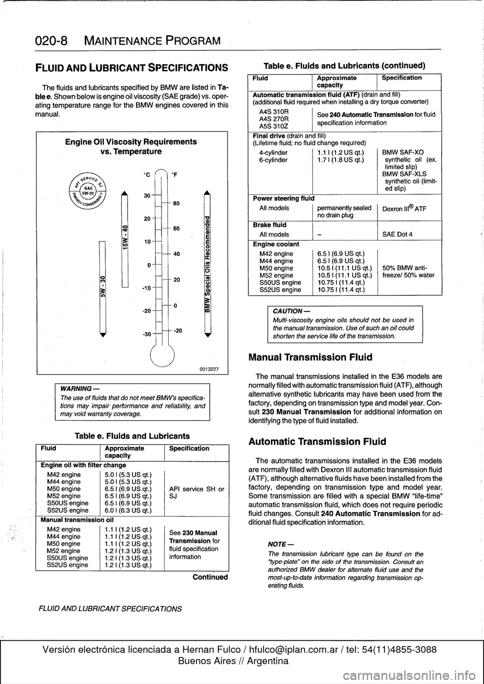
FLUID
AND
LUBRICANT
SPECIFICATIONS
The
fluids
and
lubricante
specified
by
BMW
are
listed
in
Ta-
ble
e
.
Shown
below
is
engine
oil
viscosity
(SAE
grade)
vs
.
oper-
ating
temperature
range
for
the
BMW
enginescovered
in
this
manual
.
Engine
Oil
Viscosity
Requirements
vs
.
Temperature
`S
EAVic
P
Q
SAE
swao
YCO
0
N
M42
engine
1
.1
I
(1
.2
US
qt
.)
M44
engine
1
.1
l(1.2
US
qt
.)
M50
engine
1
.1
1(1.2
US
qt
.)
M52
engine
1
.21(1.3
US
qt
.)
S50US
engine
1
.21(1.3
US
qt
.)
S52US
engine
1
.21(1.3
US
qt
.)
°F
80
-
1o-0
-
30
-----20
WARNING
-
The
use
of
fluids
that
do
not
meet
BMWs
specifica-
tions
may
impair
performance
and
refability,
and
may
void
warranty
coverage
.
Tablee
.
Fluids
and
Lubricants
0013227
Fluid
Approximate
Specification
capacity
Engine
oil
with
filter
change
M42
engine
5
.01
(5
.3
US
qt
.)
M44
engine
5
.0
I
(5
.3
US
qt
.)
M50
engine
6
.5
I
(6.9
US
qt
.)
API
service
SH
or
M52
engine
6
.51
(6.9
US
qt
.)
si
S50US
engine
6
.51
(6.9
US
qt
.)
S52US
engine
6.0
I
(6.3
US
qt
.)
Manual
transmission
oil
FLUID
AND
LUBRICANT
SPECIFICATIONS
See
230Manual
Transmission
for
NOTE-
fluid
specification
Tablee
.
Fluids
and
Lubricants
(continued)
Fluid
Approximate
Specification
capacity
Automatic
transmission
fluid
(ATF)
(drain
and
fill)
(additional
fluid
required
when
installing
a
drytorque
converter)
A4S
310R
See240
AutomaticTransmission
for
fluid
A4S
270R
specification
information
A5S
310Z
Final
drive
(drain
and
fill)
(Lifetime
fluid
;
no
fluid
change
required)
4-cylinder
1
.1
I
(1.2
US
qt
.)
BMW
SAF-XO
6-cylinder
1.7
l(1
.8
US
qt
.)
synthetic
oil
(ex
.
limited
slip)
BMW
SAF-X1-S
synthetic
oil
(limit-
ed
slip)
Power
steering
fluid
Al¡
modeis
permanentlysealed
Dexron
IIPATFno
drain
plug
rake
fluid
All
modeis
-
~
S
AE
Dot4
Engine
coolant
M42
engine
6
.51(6
.9
US
qt
.)
M44
engine
6
.51(6
.9
US
qt
.)
M50
engine
10
.51
(11
.1
US
qt
.)
50%
BMW
anti-
M52
engine
10
.5
1
(11
.1
US
qt
.)
freezel
50%
water
S50US
engine
10
.75
1(11
.4
qt
.)
S52US
engine
10
.75
I
(11
.4
qt
.)
CA
UTION-
Multi-viscosity
engine
oils
should
not
beused
in
the
manual
transmission
.
Use
of
such
an
oil
could
shorten
the
service
life
of
thetransmission
.
Manual
Transmission
Fluid
The
manual
transmissions
installed
in
the
E36
modeis
are
normallyfilled
with
automatic
transmission
fluid
(ATF),
although
alternative
synthetic
lubricants
may
havebeen
used
from
-
the
factory,
depending
on
transmission
type
and
model
year
.
Con-
sult
230
Manual
Transmission
for
additional
information
on
identifying
the
type
of
fluid
installed
.
Automatic
Transmission
Fluid
The
automatic
transmissions
installed
in
the
E36
modeis
are
normally
filled
with
Dexron
111
automatic
transmission
fluid
(ATF),
although
alternative
fluids
havebeen
installed
from
the
factory,
depending
on
transmission
type
and
model
year
.
Some
transmission
are
filled
with
a
special
BMW
"life-time"
automatic
transmission
fluid,
whích
does
not
requireperiodic
fluid
changes
.
Consult
240
Automatic
Transmission
for
ad-
ditional
fluid
specification
information
.
information
1
The
11-
11
lubrican
type
canbefound
on
ti
¡e
`Yype
plate"
on
the
side
of
the
transmission
.
Consult
an
authorized
BMW
dealer
foralternate
fluid
use
and
the
Continued
most-up-to-date
information
regarding
transmission
op-
erating
fluids
.
Page 31 of 759
Final
Drive
Gear
Oil
BMW
recommends
using
only
a
specially
formulatedsyn-
thetic
gear
oil
that
is
available
through
an
authorized
BMW
dealer
parts
department
.
For
additional
information
on
this
¡u-
bricant
andany
other
lubricants
that
may
be
compatible,
con-
tact
an
authorized
BMW
dealer
senrice
department
.
See
331
Final
Drive
.
Brake
Fluid
Brake
fluid
absorbs
moisture
easily,
and
moisture
in
the
fluid
affects
brake
performance
and
reliability
.
This
is
why
brake
fluid
should
be
flushed
from
the
system
every
two
years
.
When
re-
placing
or
adding
brake
fluid,
use
only
new
(luid
from
previously
unopened
containers
.
Do
not
use
brake
fluid
that
has
been
bled
from
the
system,
even
ifit
is
brand
new
.
Use
only
DOT
4
brake
fluid
.
See340
Brakes
for
more
information
.
Engine
Coolant
(Anti-freeze)
BMW
recommends
coolant
that
is
a
50/50
mixture
of
distilled
water
and
phosphate/nítrate
freeanti-freeze
containing
ethyl-
ene
glycol
.
Anti-freezeraises
the
boiling
point
and
lowersthe
freezingpoint
of
the
coolant
.
It
alsocontains
additives
that
help
prevent
cooling
system
corrosion
.
Power
Steering
Fluid
The
power
steering
fluid
is
Dexron
II]®
ATF,
or
equivalent
.
The
system
is
permanently
filled
and
does
not
have
a
drain
.
Routinely
adding
ATF
is
not
required
unlessthe
system
is
leak-
i
n
g,
WARNING
-
Be
sure
to
check
the
fluid
specifications
on
the
pow-
er
steering
reservoir
to
confirm
the
fluid
type
in-
stalled
in
the
system
.
In
some
instances,
the
power
steering
system
may
be
filled
with
an
alternative
hy-
draulic
fluid
designated
CHF
7
.1
.
MAINTENANCE
PROGRAM
020-
ENGINE
OIL
SERVICE
Engine
oil
and
fiiter,
changing
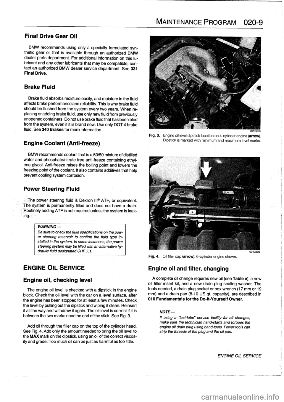
Fig
.
3
.
Engine
oil
level
dipsticklocation
on
4-cylinder
engine
(arrow)
.
Dipsfck
is
marked
with
mínimum
and
maximum
level
marks
.
Fig
.
4
.
Oil
filler
cap
(arrow)
.
6-cylinder
engine
shown
.
0012202
Engine
oii,
checking
leve¡
A
complete
oil
change
requires
new
oil
(see
Table
e),
a
new
oil
filter
insert
kit,
and
a
new
drain
plug
sealing
washer
.
The
The
engine
oil
leve]
is
checked
with
a
dipstick
in
the
engine
tools
needed,
a
drain
plug
socket
or
box
wrench
(17
mm
or19
block
.
Check
the
oii
leve¡
with
the
canon
a
level
surface,
after
mm)
and
a
drain
pan
(8-10
US
qt
.
capacity),
are
described
in
the
engine
has
been
stopped
for
atleast
a
few
minutes
.
Check
010
Fundamentals
for
the
Do-It-Yourself
Owner
.
the
leve¡
by
pulling
outthe
dipstick
and
wiping
it
clean
.
Reinsert
it
all
the
way
and
withdraw
it
again
.
The
oil
leve¡
is
correct
if
it
is
NOTE-
between
the
two
marks
near
the
end
of
the
stick
.
See
Fig
.
3
.
If
using
a
"fast-lube"
service
facility
for
oil
changes,
make
sure
the
technician
hand-starts
and
torques
the
Add
oil
through
the
filler
cap
on
thetop
of
the
cylinder
head
.
engine
oil
drain
plug
using
hand-tools
.
Power
tools
can
See
Fig
.
4
.
Add
only
the
amount
needed
to
bring
the
oil
leve¡to
strip
the
threads
of
the
plug
and
the
oil
pan
.
the
MAX
mark
on
the
dipstick,
using
an
oil
of
the
correctviscos-
ity
andgrade
.
Too
much
oil
canbe
just
as
harmful
as
too
little
.
ENGINE
OIL
SERVICE
Page 36 of 759
020-
1
4
MAINTENANCE
PROGRAM
uu11989
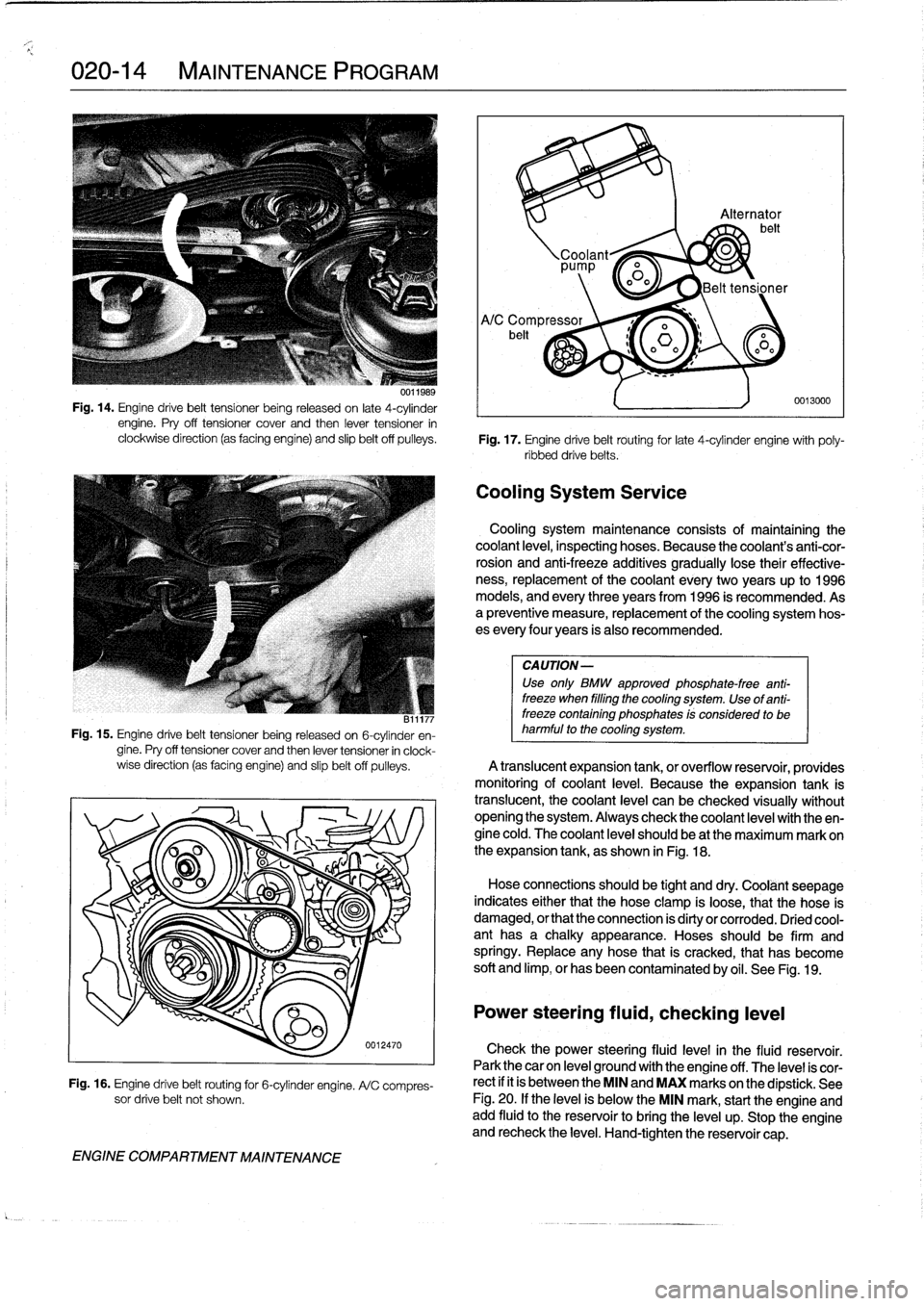
Fig
.
14
.
Engine
drive
belt
tensíoner
being
released
on
late
4-cylinder
engine
.
Pry
off
tensioner
cover
and
then
lever
tensioner
in
clockwise
direction
(as
facing
engine)
and
slip
beltoff
pulleys
.
Fig
.
17
.
Engine
drive
belt
routing
for
late
4-cylinder
engine
with
poly-
ribbed
drivebelts
.
CA
UTION-
Use
only
BMW
approved
phosphate-free
anti-
freeze
when
filling
the
cooling
system
.
Use
of
anti-
B11177
freeze
containing
phosphates
!s
considerad
to
be
Fig
.
15
.
Engine
drive
belt
tensioner
being
released
on
6-cylinder
en-
harmful
to
the
cooling
system
.
gine
.
Pry
off
tensioner
cover
and
then
lever
tensioner
in
clock-
wise
direction
(as
facing
engine)
and
slipbelt
off
pulleys
.
A
translucent
expansion
tank,
or
overflow
resenroir,
providesmonitóring
of
coolant
leve¡
.
Because
the
expansion
tank
is
translucent,
thecoolant
level
can
be
checked
visually
without
opening
the
system
.
Always
check
thecoolant
leve¡
with
theen-gine
cold
.
The
coolant
leve¡
should
be
at
the
maximum
mark
on
O
o
'~
I
the
expansion
tank,
as
shown
in
Fig
.
18
.
OO
Hose
connectionhld
b
tiht
s
soueg
an
ddry
.
Coolánt
seepage
indicates
either
that
the
hose
clamp
is
loose,
that
the
pose
is
ENGINE
COMPARTMENT
MAINTENANCE
0012470
Fig
.
16
.
Engine
drive
belt
routing
for
6-cylinder
engine
.
A/C
compres-
sor
drive
belt
not
shown
.
'92
irá
Alternator
belt
Coolant~
0
pp
o0o
Belt
tensioner
Cooling
System
Service
0013000
Cooling
system
maintenance
consists
of
maíntaining
thecoolant
leve¡,
inspecting
hoses
.
Because
the
coolant's
anti-cor-
rosion
and
anti-freeze
additives
gradually
lose
their
effective-
ness,
replacement
of
thecoolant
every
two
years
up
to
1996
models,
and
every
three
years
from
1996
is
recommended
.
Asa
preventive
measure,
replacement
of
the
cooling
system
hos-
es
every
four
years
is
also
recommended
.
damaged,
or
that
the
connection
is
dirty
or
corroded
.
Dried
cool-
ant
has
a
chalky
appearance
.
Hoses
should
be
firm
and
springy
.
Replace
any
hose
that
is
cracked,
that
has
become
soft
and
limp,
or
has
been
contaminated
by
oil
.
See
Fig
.
19
.
Power
steering
fluid,
checking
leve¡
Check
the
power
steering
fluid
level
in
the
fluid
reservoir
.
Park
thecar
on
leve¡
ground
with
the
engine
off
.
The
level
is
cor-
rect
if
it
is
between
the
MIN
and
MAX
marks
on
the
dipstick
.
See
Fig
.
20
.
If
the
leve¡
is
below
the
MIN
mark,
start
the
engine
andadd
fluid
to
the
reservoir
to
bríng
the
leve¡
up
.
Stop
the
engine
and
recheck
the
leve¡
.
Hand-tighten
the
reservoir
cap
.
Page 200 of 759
170-6
RADIATOR
AND
COOLING
SYSTEM
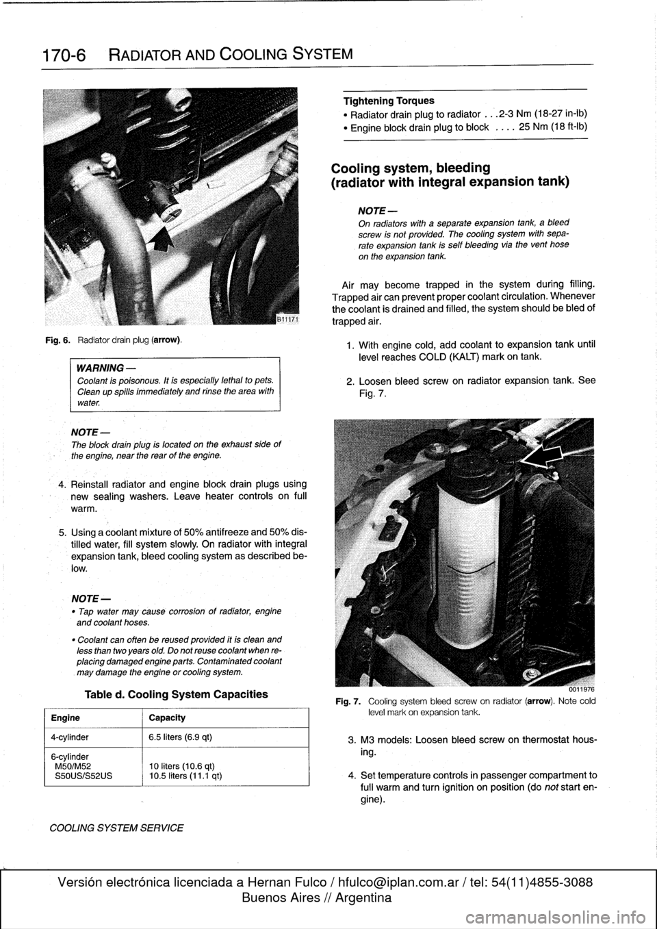
Fig
.
6
.
Radiator
drain
plug
(arrow)
.
WARNING
-
Coolant
is
poisonous
.
Itis
especially
lethal
to
pets
.
Cleanup
spills
immediately
and
rinse
the
area
with
water
.
NOTE
-
The
block
drain
plug
is
located
on
the
exhaust
side
of
the
engine,
near
the
reas
of
the
engine
.
4
.
Reinstall
radiator
and
engine
block
drain
plugsusing
new
sealing
washers
.
Leave
heater
controis
on
full
warm
.
5
.
Using
a
coolantmixture
of
50%
antifreeze
and
50%
dis-
tilled
water,
fill
system
slowly
On
radiator
with
integral
expansion
tank,
bleed
cooling
system
as
described
be-
low
.
NOTE-
"
Tap
water
may
cause
corrosion
of
radiator,
engine
and
coolant
hoses
.
"
Coolant
can
often
be
reused
provided
itis
clean
and
less
than
twoyears
old
.
Do
not
reuse
coolant
when
re-
placing
damaged
engine
parts
.
Contaminated
coolant
may
damage
the
engine
or
cooling
system
.
Tabled
.
Cooling
System
Capacities
Engine
j
Capacity
4-cylinder
1
6
.5
liters
(6.9
qt)
6-cylinder
M50/M52
10
liters
(10
.6
qt)
S50US/S52US
10
.5
liters
(11
.1
qt)
COOLING
SYSTEM
SERVICE
Tightehing
Torques
"
Radiator
drain
plug
to
radiator
...
2-3
Nm
(18-27
in-lb)
"
Engine
block
drain
plug
to
block
.
.
..
25
Nm
(18
ft-Ib)
Cooling
system,
bleeding
(radiator
with
integral
expansion
tank)
NOTE
-
On
radiators
with
a
separate
expansion
tank,
ableed
screw
is
not
provided
.
The
cooling
system
with
sepa-
rate
expansion
tank
is
self
bleeding
via
the
vent
hose
on
the
expansion
tank
.
Air
maybecome
trapped
in
the
system
during
filling
.
Trapped
air
can
prevent
proper
coolant
circulation
.
Whenever
the
coolant
is
drained
and
filled,
the
system
should
be
bled
of
trapped
air
.
1
.
With
engine
cold,
add
coolant
to
expansion
tank
until
level
reaches
COLD
(KALT)
mark
on
tank
.
2
.
Loosen
bleed
screw
on
radiator
expansion
tank
.
See
Fig
.
7
.
0011976
Fig
.
7
.
Cooling
system
bleed
screwon
radiator
(arrow)
.
Note
cold
level
mark
on
expansion
tank
.
3
.
M3
models
:
Loosen
bleed
screw
on
thermostathous-
ing
.
4
.
Set
temperature
controls
in
passenger
compartment
to
fui¡
warm
and
turn
ignition
on
position
(do
not
start
en-
gine)
.
Page 201 of 759
5
.
Slowly
add
coolant
until
it
spills
from
bleed
screws
.
When
coolant
spillíng
from
bleed
screws
is
free
of
air
bubbies,
tighten
screws
.
6
.
Run
engine
until
it
reaches
operatíng
temperature
.
Af-
ter
engine
has
cooled,
recheck
coolant
level
and
top
up
as
necessary
.
CAUTION-
Always
use
genuine
BMW
coolant
or
its
equiva-
lent
to
avoid
the
formation
of
harmful,
clogging
de-
posits
in
the
cooling
system
.
Use
of
other
antifreeze
solutions
may
be
harmful
to
the
cooling
system
.
Tightening
Torque
"
Radiator
bleed
screw
to
thermostat
housing
...
.
.
........
8
Nm
(71
in-lb)
Belt-driven
cooling
fan,
replacing
1
.
Usinga32
mm
wrench
on
fan
clutch
nut,
turn
wrench
quickly
in
a
clockwise
direction
(working
from
front
of
car)
to
loosen
.
Spin
fan
off
pump
.
See
Fig
.
8
.
NOTE-
"
The
radiator
cooling
fan
nut(32
mm
wrench)
has
left-
hand
threads
.
"
The
nut
may
be
difficult
to
loosen
.
Use
a
tool
to
hold
the
coolant
pump
pulleystationary
.
BMW
hasa
spe-
cial
tool
forthis
purpose
(BMW
special
tool
no
.
115
030)
.
2
.
Remove
expansion
rivets
holding
shroud
to
radiator
.
See
Fig
.
9
.
Remove
fan
and
shroud
together
.
NOTE-
Store
the
removed
fan
clutch
assembly
in
an
upright
(installed)
positionto
prevent
lossof
clutch
fluid
.
RADIATOR
AND
COOLING
SYSTEM
170-
7
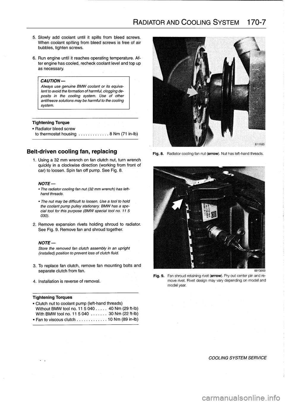
Fig
.
8
.
Radiatorcooling
fannut
(arrow)
.
Nuthas
left-hand
threads
.
3
.
To
replace
fan
clutch,
remove
fan
mounting
bolts
and
separate
clutch
from
fan
.
Fig
.
9
.
Fan
shroud
retaining
rivet
(arrow)
.
Pryout
center
pin
and
re
4
.
Installation
is
reverse
of
rernoval
.
move
rivet
.
Rivet
design
may
vary
depending
on
model
and
model
year
.
Tightening
Torques
"
Clutchnut
to
coolant
pump
(left-hand
threads)
Wíthout
BMW
tool
no
.
11
5
040
.....
40
Nm
(29
ft-lb)
With
BMW
tool
no
.
11
5
040
.
......
30
Nm
(22
ft-Ib)
"
Fan
to
viscous
clutch
...
.
..
.
......
10
Nm
(89
in-lb)
0013203
COOLING
SYSTEM
SERVICE