Soft too BMW 318i 1997 E36 Workshop Manual
[x] Cancel search | Manufacturer: BMW, Model Year: 1997, Model line: 318i, Model: BMW 318i 1997 E36Pages: 759
Page 13 of 759
FUNDAMENTALS
FOR
THEDO-ITYOURSELF
OWNER
010-
5
WARNING
-
Avoid
getting
tools
or
clothing
near
the
battery
.
Bat-tery
electrolyte
is
a
corrosive
acid
.
Be
careful
with
brake
fluid,
as
it
can
damage
the
cars
paint
Finally,
keep
rubber
parts
such
as
hoses
and
bolts
free
from
oil
orgasoline,
as
they
will
cause
the
material
to
soften
and
fail
prematurely
.
Non-reusable
Fasteners
Many
fasteners
usedon
the
cars
coveredby
this
manual
mustbe
replaced
with
new
osesonce
they
are
removed
.
These
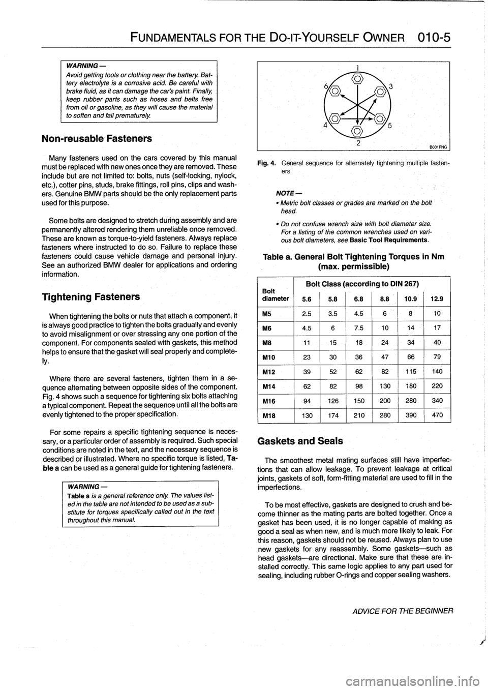
Fig
.
4
.
General
sequence
for
alternately
tightening
multiple
fasten-
include
butarenot
limited
to
:
bolts,
nuts
(self-locking,
nylock,
ers
.
etc
.),
cotterpins,
studs,
brake
fittings,
rol¡
pins,clips
and
wash-
ers
.
Genuine
BMW
parts
should
be
the
only
replacement
parts
NOTE-
used
for
this
purpose
.
"
Metric
bolt
classes
or
grades
are
markedon
the
bolt'
head
.
Some
bolts
are
designed
to
stretch
during
assembly
and
are
permanently
altered
rendering
them
unreliable
once
removed
.
These
are
known
as
torque-to-yield
fasteners
.
Always
replace
fasteners
where
instructed
to
doso
.
Failure
to
replace
these
fasteners
could
cause
vehicle
damage
and
personal
injury
.
See
an
authorized
BMW
dealer
for
applications
and
ordering
information
.
Tightening
Fasteners
When
tighteningthe
bolts
ornuts
that
attach
acomponent,
it
is
always
good
practice
to
tighten
the
bolts
gradually
and
evenly
to
avoid
misalignment
or
over
stressing
anyone
portion
of
the
component
.
For
components
sealed
with
gaskets,
this
method
helps
to
ensure
that
thegasket
will
seal
properly
and
complete-
ly
.
Where
there
are
severa¡
fasteners,
tighten
them
in
a
se-
quence
alternating
between
opposite
sides
of
the
component
.
Fig
.
4
shows
such
a
sequence
for
tightening
six
bolts
attaching
a
typical
component
.
Repeat
the
sequence
until
al¡
the
bolts
are
evenly
tightened
to
theproper
specification
.
"
Do
not
confuse
wrench
sizewithbolt
diameter
size
.
Fora
listing
of
the
common
wrenches
used
on
vari-
ous
bolt
diameters,
see
Basic
Tool
Requirements
.
Table
a
.
General
Bolt
Tightening
Torques
in
Nm
(max
.
permissible)
Bolt
Class
(according
to
DIN
267)
Bolt
diameter
5
.6
5
.8
6
.8
8
.8
10
.9
12
.9
M5
2
.5
3
.5
4
.5
6810
M6
4
.5
6
7
.5
10
14
`
17
M8
11
15
-
18
24
34
40
M10
233036476679
M12
3952
62
82115140
M14
6282
98
130
180220
M16
9426150
200280340
M18
130174210280
390
470
For
some
repairs
a
specific
tightening
sequence
is
neces-
sary,
or
a
particular
order
of
assembly
is
required
.
Such
special
Gaskets
and
Seals
conditions
are
noted
in
the
text,
and
the
necessary
sequence
is
described
or
illustrated
.
Where
no
specific
torque
is
listed,
Ta-
The
smoothest
metal
mating
surfaces
still
have
imperfec
blea
can
be
used
as
a
general
guide
for
tightening
fasteners
.
tions
that
can
allow
leakage
.
To
prevent
leakage
atcritica¡
joints,
gaskets
of
soft,
form-fitting
material
are
used
to
fill
in
the
WARNING
-
imperfections
.
Table
ais
a
general
reference
only
.
The
values
list-
ed
in
the
table
are
not
intended
to
be
used
asa
sub-
To
be
most
effective,
gaskets
are
designed
to
crush
and
be-
stitutefor
torques
specifically
called
out
in
the
text
come
thinner
as
the
mating
parts
are
bolted
together
.
Once
a
throughout
this
manual
.
gasket
has
been
used,
it
is
no
longer
capable
of
makingas
good
a
sea¡
as
when
new,
and
is
muchmore
likely
toleak
.
For
this
reason,
gaskets
should
not
be
reused
.
Always
plan
to
use
new
gaskets
for
any
reassembly
.
Some
gaskets-such
as
head
gaskets-are
directional
.
Make
sure
that
these
are
in-
stalled
correctly
.
This
same
logic
applies
to
any
part
used
for
sealing,
including
rubber
O-rings
and
copper
sealing
washers
.
ADVICE
FOR
THE
BEGINNER
Page 19 of 759
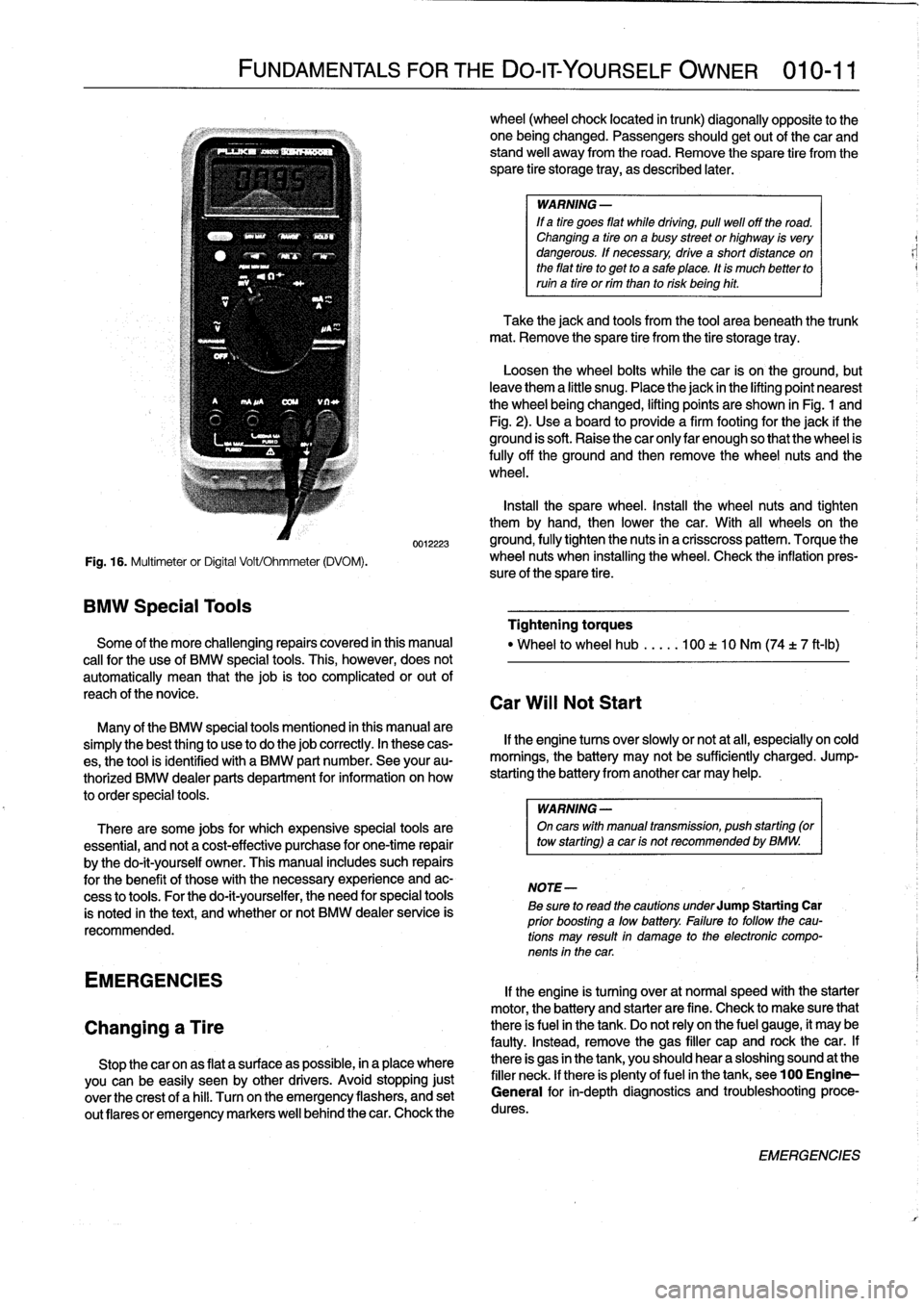
Fig
.
16
.
Multimeter
or
Digital
Volt/Ohmmeter
(DVOM)
.
BMW
Special
Tools
FUNDAMENTALS
FOR
THE
DO-ITYOURSELF
OWNER
010-11
0012223
Some
of
the
more
challenging
repairs
covered
in
this
manual
cal¡
for
the
use
of
BMW
special
tools
.
This,
however,
does
not
automatically
mean
that
thejob
is
too
complicated
or
out
of
reach
of
thenovice
.
Many
of
the
BMW
special
tools
mentioned
in
this
manual
are
simplythe
best
thing
to
use
to
do
thejob
correctly
.
In
these
cas-
es,
the
tool
is
identified
with
a
BMW
part
number
.
See
your
au-
thorized
BMW
dealer
parts
department
for
information
on
how
to
order
special
tools
.
There
are
some
jobs
for
which
expensive
special
tools
are
essential,
and
not
a
cost-effective
purchase
for
one-time
repair
by
the
do-it-yourself
owner
.
This
manual
includes
such
repairs
for
the
benefit
of
these
with
the
necessary
experience
and
ac-
cess
to
tools
.
For
the
do-it-yourselfer,
the
need
for
special
tools
is
noted
in
the
text,
and
whether
or
not
BMW
dealer
service
is
recommended
.
EMERGENCIES
Changing
a
Tire
Stop
thecar
onas
flat
a
surface
as
possible,
in
a
place
where
you
canbe
easily
seen
by
other
drivers
.
Avoid
stopping
just
over
the
crest
of
a
hill
.
Turnon
the
emergency
flashers,
and
set
out
(lares
or
emergency
markers
well
behindthecar
.
Chock
the
wheel
(wheel
chock
located
in
trunk)
diagonally
opposite
to
the
one
being
changed
.
Passengers
shouldgetout
of
thecar
and
stand
well
away
from
the
road
.
Remove
the
spare
tire
from
the
spare
tire
storage
tray,
as
described
later
.
WARNING
-
If
a
tire
goes
fíat
while
drtving,
pull
well
off
the
road
.
Changing
a
tire
ona
busy
street
or
highway
is
very
dangerous
.
If
necessary,
drive
a
short
distance
on
the
fíat
tire
to
get
to
a
sale
place
.
tt
is
much
better
to
ruin
a
tire
or
rim
than
to
risk
being
hit
.
Take
the
jack
and
tools
from
the
tool
area
beneath
the
trunk
mat
.
Remove
the
spare
tire
from
the
tire
storage
tray
.
Loosen
the
wheel
bolts
while
the
car
is
on
the
ground,
but
leave
them
a
little
snug
.
Placethe
jack
in
the
lifting
point
nearest
the
wheel
beingchanged,
lifting
points
are
shown
in
Fig
.
1
and
Fig
.
2)
.
Use
a
board
to
provide
a
firm
footing
for
the
jack
if
the
ground
is
soft
.
Raise
the
car
only
lar
enough
so
that
the
wheel
is
fully
off
the
ground
and
then
remove
the
wheel
nuts
and
the
wheel
.
Insta¡¡
the
spare
wheel
.
Install
the
wheel
nuts
and
tighten
them
by
hand,
then
lower
the
car
.
With
all
wheelson
the
ground,
fully
tighten
the
nuts
in
a
crisscross
pattern
.
Torque
the
wheel
nuts
when
installing
the
wheel
.
Check
the
inflation
pres-
sure
of
the
spare
tire
.
Tightening
torques
"
Wheel
to
wheel
hub
.....
100
t
10
Nm
(74
t
7
ft-Ib)
Car
Will
Not
Start
If
the
engine
tucos
over
slowly
or
not
at
all,
especially
on
cold
mornings,
the
battery
may
not
be
sufficiently
charged
.
Jump-
starting
the
battery
from
another
car
may
help
.
WARNING
-
On
carswith
manual
transmisston,
push
starting
(or
tow
starting)
acar
ts
not
recommended
by
BMW
.
NOTE-
Be
sure
to
read
the
cautions
underJump
Starting
Car
prior
boosting
a
low
battery
.
Fatlure
to
followthe
cau-
tions
may
result
in
damage
to
the
electronic
compo-
nents
in
the
car
.
If
the
engine
is
turning
over
at
normal
speed
with
the
starter
motor,
the
battery
and
starter
are
fine
.
Check
to
make
sure
that
there
is
fuel
in
the
tank
.
Do
not
rely
on
the
fuel
gauge,
it
may
be
faulty
.
Instead,
remove
the
gas
filler
cap
and
rock
thecar
.
If
there
is
gas
in
the
tank,
you
should
hear
a
sloshing
sound
at
the
filler
neck
.
lf
there
is
plenty
offuel
in
the
tank,
see100
Engine-
General
for
in-depth
diagnostics
and
troubleshootingproce-
dures
.
EMERGENCIES
Page 74 of 759
113-8
CYLINDER
HEAD
REMOVAL
AND
INSTALLATION
IW?
-
L
'/~f
W
~
4r
"
-
"
;,s
1
12
.
On
M44
engine
:
Place
sensor
wheel
on
intake
cam-
shaft
sprocket
so
that
arrowon
sensor
wheel
points
up
.
13
.
Instan
and
hand-tighten
sprocket
mounting
bolts
.
CAUTION-
Different
hydraulic
chaintensioners
were
used
during
manufacture,
depending
onengine
type
.
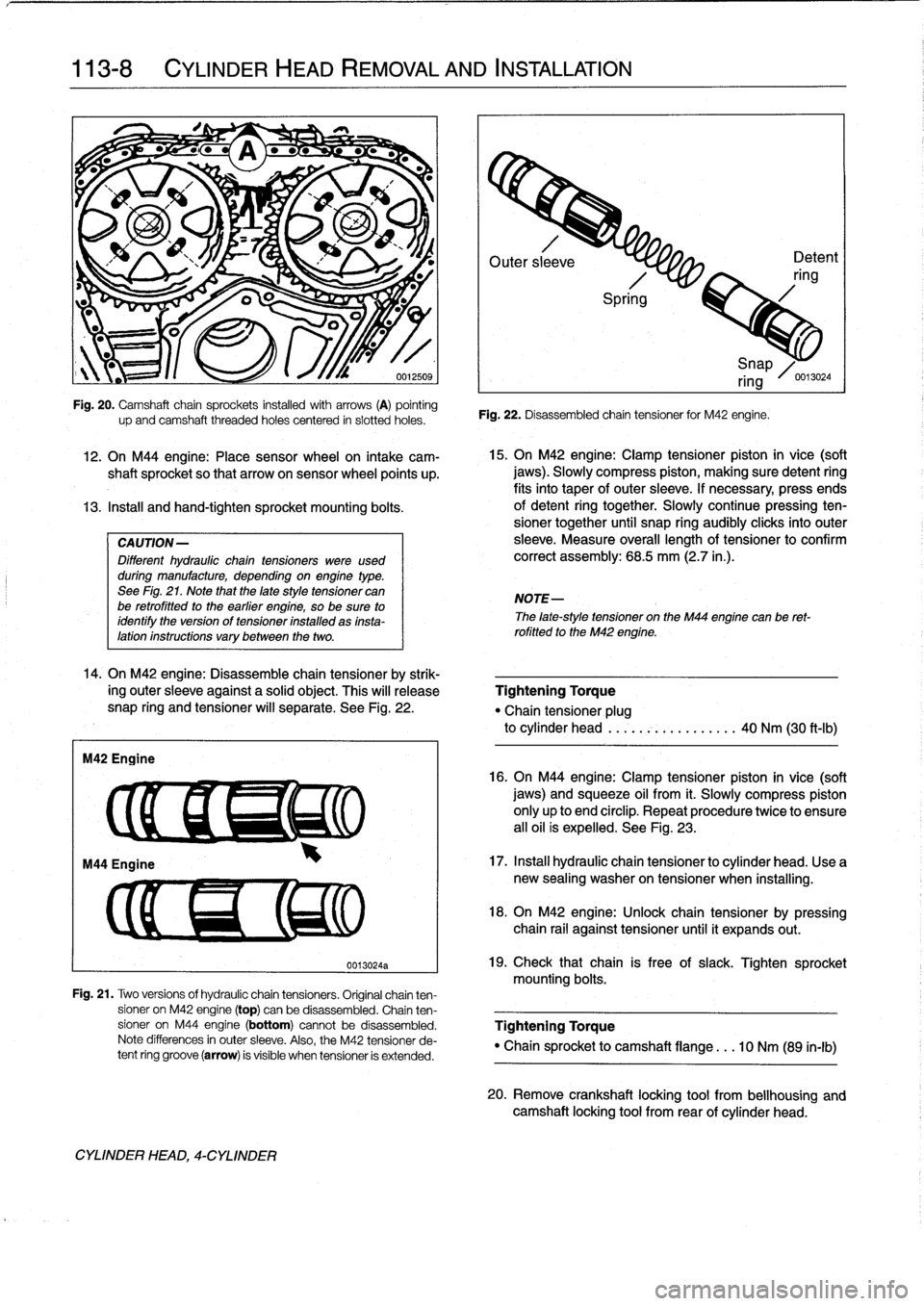
See
Fig
.
21
.
Note
that
the
late
style
tensioner
can
be
retrofitted
to
the
earlier
engine,
so
be
sure
to
identify
the
version
of
tensioner
installed
as
insta-lation
instructions
vary
between
the
two
.
14
.
On
M42
engine
:
Disassemble
chain
tensioner
by
strik-
ing
outer
sleeve
against
a
solid
object
.
This
will
release
snap
ring
and
tensioner
will
separate
.
See
Fig
.
22
.
M42
Engine
up
and
camshaft
threaded
holes
centered
in
siotted
holes
.
CYLINDER
HEAD,
4-CYLINDER
0013024a
Outer
sl
eve
Detent
ring
Spri
g
Fig
.
22
.
Disassembled
chain
tensioner
for
M42
engine
.
15
.
On
M42
engine
:
Clamp
tensioner
piston
in
vice
(soft
jaws)
.
Slowly
compress
piston,
making
sure
detent
ring
fits
into
taper
of
outer
sleeve
.
If
necessary,
press
ends
of
detent
ring
together
.
Slowly
continuepressing
ten-
sioner
together
until
snap
ring
audibly
clicksinto
outer
sleeve
.
Measure
overall
lengthof
tensioner
to
confirm
correct
assembly
:
68
.5
mm
(2.7
in
.)
.
NOTE-
i
Snap
ring
/0
.13024
The
late-style
tensioner
on
the
M44
engíne
canbe
ret-
rofitted
to
the
M42
engine
.
Tightening
Torque
"Chain
tensioner
plug
to
cylinder
head
.....
.-~
..........
40
Nm
(30
ft-Ib)
16
.
On
M44
engíne
:
Clamp
tensioner
píston
in
vice
(soft
jaws)
and
squeeze
oil
from
it
.
Slowly
compress
piston
only
up
to
end
circlip
.
Repeat
procedure
twice
to
ensure
all
oil
is
expelled
.
See
Fig
.
23
.
17
.
Instan
hydraulic
chain
tensioner
to
cylinder
head
.
Use
a
new
sealing
washer
on
tensioner
when
installing
.
18
.
On
M42
engine
:
Unlock
chain
tensioner
by
pressing
chain
rail
against
tensioner
until
it
expands
out
.
19
.
Check
that
chain
is
free
of
slack
.
Tighten
sprocket
mounting
bolts
.
Fig
.
21
.
Two
versions
of
hydraulic
chain
tensioners
.
Original
chainten-
sioner
on
M42
engine
(top)
can
be
disassembled
.
Chain
ten
sioner
on
M44
engine
(bottom)
cannotbe
disassembled
.
Tightening
Torque
Note
differences
in
outer
sleeve
.
Also,
the
M42
tensioner
de-
"
Chain
sprocket
to
camshaft
flange
.
..
10
Nm
(89
in-lb)
tent
ring
groove
(arrow)
is
visible
when
tensioner
is
extended
.
20
.
Remove
crankshaft
locking
tool
from
bellhousing
and
camshaft
locking
tool
from
rear
of
cylinder
head
.
Page 100 of 759
117-
4
CAMSHAFT
TIMING
CHAIN
15
.
Remove
mounting
bolts
from
left
and
right
camshaft
4
.
Insta¡¡
and
hand-tighten
sprocket
mounting
bolts
.
sprockets
.
16
.
On
M42
engines,
remove
upper
bolt
on
right
side
chainguide
and
unbolt
lower
timing
chainguide
below
crank-
shaft
.
17
.
Remove
camshaft
sprockets
from
camshafts
together
with
chain
and
crankshaft
sprocket
.
NoteWoodruffkey
when
removing
crankshaftsprocket
.
CA
UTION-
The
crankshaft
must
not
be
allowed
to
rotate
when
the
timing
chaín
is
removed
.
The
pistons
can
contact
the
valves
.
Camshaft
timing
chain,
installing
(4-cylinder
engines)
Inspectal¡
sprockets
for
wear
or
damage
.
Inspect
the
chain
guide
and
tensioner
rails
for
grooves
caused
by
chain
contact
.
Replace
any
partthat
is
worn
.
If
any
of
the
sprockets
are
worn,
the
chain
and
sprocketsare
replaced
asan
assembly
.
The
procedure
outlined
below
assumes
that
the
camshafts
and
the
crankshaft
arelocked
in
the
TDC
installation
positionwithspecial
tools
(shown
earlier
in
Fig
.
5
and
Fig
.
6)
.
1
.
Install
timing
chain
to
crankshaft
sprocket,
then
slide
sprocket
on
crankshaft
whílealigníng
woodruff
key
.
2
.
Place
camshaft
sprockets
on
chain,
then
place
sprock-
ets
oncamshafts
so
that
arrows
on
sprockets
point
up
and
elongatedholes
in
sprockets
are
centered
lo
tapped
holes
in
camshafts
.
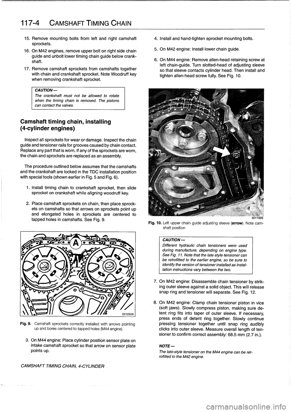
See
Fig
.
9
.
.
I
Pa
-
s
~_
a
Ge
..
.
0012509
5
.
On
M42
engine
:
Install
lowerchainguide
.
6
.
On
M44
engine
:
Remove
allen-head
retaining
screw
at
left
chain-guide
.
Turn
slotted-head
of
adjusting
sleeve
so
that
sleeve
contacts
cylinder
head
.
Then
install
and
tighten'allen-head
screw
fully
.
See
Fig
.
10
.
Fig
.
10
.
Left
upper
chain
guide
adjusting
sleeve
(arrow)
.
Note
cam-
shaft
position
CAUTION-
Different
hydraulic
chaintensioners
were
used
duringmanufacture,
depending
onengíne
type
.
See
Fig
.
11
.
Note
that
the
late
style
tensioner
canbe
retrofitted
to
the
earlier
engíne,
so
be
sure
to
identify
the
versíon
of
tensioner
ínstalled
as
ínstal-
lation
instructions
vary
between
the
two
.
7
.
On
M42
engine
:
Disassemble
chain
tensioner
by
strik-
ing
outer
sleeve
against
a
solid
object
.
This
will
release
snap
ring
and
tensioner
will
separate
.
See
Fig
.
12
.
8
.
On
M42
engine
:
Clamp
chain
tensioner
piston
in
vice
(soft
jaws)
.
Slowly
compress
piston,
making
sure
de-
tent
ring
fits
into
taper
of
outer
sleeve
.
If
necessary,
press
ends
of
detent
ring
together
.
Slowly
continueFig
.
9
.
Camshaft
sprockets
correctly
installed
with
arrows
pointing
pressing
tensioner
together
until
snap
ring
audibly
upand
bores
centered
to
tapped
holes
(M44
engine)
.
clicks
into
outer
sleeve
.
Measure
overall
length
of
ten-
sionerto
confirm
correct
assembly
:
68
.5
mm
(2
.7
in
.)
.
3
.
On
M44
engine
:
Place
cylinder
position
sensor
plate
on
intake
camshaft
sprocket
so
that
arrowonsensor
plate
NOTE-
points
up
.
The
¡ate-style
tensioner
on
the
M44
engine
can
be
ret-rofittedto
the
M42
engíne
.
CAMSHAFT
TIMING
CHAIN,
4-CYLINDER
Page 101 of 759
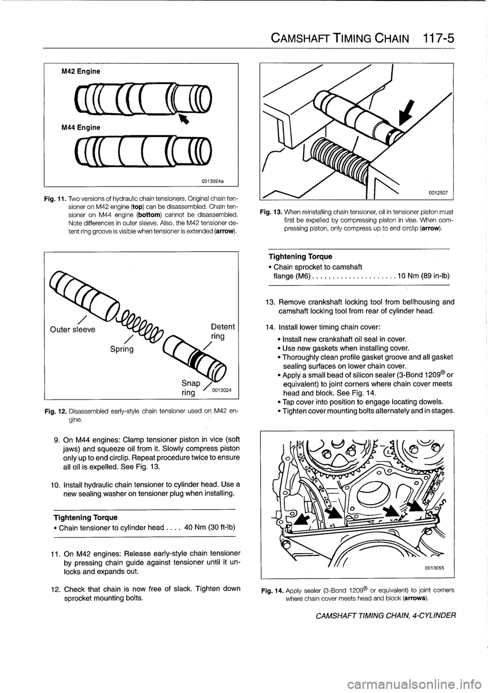
M42
Engine
CL
(EM
Fig
.
11
.
Two
versionsof
hydraulic
chaintensioners
.
Original
chain
ten-
sioner
on
M42
engine
(top)
canbe
disassembled
.
Chain
ten-
sioner
on
M44
engine
(bottom)
cannot
be
disassembled
.
Note
differences
in
outer
sleeve
.
Also,
the
M42
tensioner
de-
tent
ring
groove
is
visible
when
tensioner
is
extended
(arrow)
.
Outer
sleeve
Spring
0013024a
Detent
ring
9
.
On
M44
engines
:
Clamp
tensioner
piston
in
vice
(soft
jaws)
and
squeeze
oil
from
it
.
Slowly
compress
piston
only
up
to
end
círclip
.
Repeat
procedure
twice
to
ensure
al¡oil
is
expelled
.
See
Fig
.
13
.
10
.
Insta¡¡
hydraulic
chain
tensioner
lo
cylinder
head
.
Usea
new
sealing
washer
on
tensionerplug
when
installing
.
Tightening
Torque
"
Chain
tensioner
to
cylinder
head
....
40
Nm
(30
ft-Ib)
11
.
On
M42
engines
:
Release
early-style
chain
tensioner
by
pressing
chain
guide
against
tensioner
until
it
un-
locks
and
expands
out
.
CAMSHAFT
TIMING
CHAIN
117-
5
0012507
Fig
.
13
.
When
reinstalling
chain
tensiones,
oil
in
tensioner
piston
must
first
be
expelled
by
compressing
piston
in
vise
.
When
com-
pressing
piston,
only
compress
up
to
and
circlip
(arrow)
.
Tightening
Torque
"
Chain
sprocket
lo
camshaft
flange
(M6)
..
.
..
.............
.
..
10
Nm
(89
in-lb)
13
.
Remove
crankshaft
locking
tool
from
bellhousing
and
camshaft
locking
tool
from
rear
of
cylinder
head
.
14
.
Install
lower
timingchain
cover
:
"
Insta¡¡
new
crankshaft
oil
seal
in
cover
.
"
Use
new
gaskets
when
installing
cover
.
"
Thoroughly
clean
profile
gasketgroove
and
all
gasket
sealing
surfaces
on
lowerchaincover
.
"
Apply
a
small
bead
of
silicon
sealer
(3-Bond
1209
or
Snap
equivalent)
lo
joint
corners
where
chaincover
meets
ring
0013024
head
and
block
.
See
Fig
.
14
.
"
Tap
cover
into
position
to
engage
locating
dowels
.
Fig
.
12
.
Disassembled
early-style
chain
tensioner
usadon
M42
en-
"
Tighten
cover
mounting
bolts
alternately
and
in
stages
.
gine
.
12
.
Check
that
chain
is
now
free
of
siack
.
Tighten
down
sprocket
mounting
bolts
.
where
chain
cover
meets
head
and
block
(arrows)
.
Fig
.
14
.
Apply
sealer
(3-Bond
1209
0
or
equivalent)
to
joint
corners
CAMSHAFT
TIMING
CHAIN,
4-CYLINDER
Page 151 of 759
The
fuel
injection
systems
used
on
the
1996
and
later
cars
covered
bythis
manual
are
OBD
II
compliant
.
This
system
is
in-
corporated
into
both
the
Bosch
M5
.2
(M44
engine)
and
the
Si-
emens
MS
41
.1
(M52/S52US
engine)
engine
management
systems
.
OBD
II
systems
use
sophisticateddiagnostic
soft-
ware
capable
of
recognizing
and
electronically
storing
hun-
dreds
of
DTCs
in
the
system
ECM
.
DTCs
can
only
be
accessed
using
special
scan
tooltest
equipment
.
The
BMW
dealer
is
equipped
with
the
specialized
OBD
II
scan
toolto
quickly
and
efficiently
locate
engine
management
problems
.
Alternately,
a
"generic"
scan
tool
can
be
used
to
access
OBD
II
fault
informa-
tion
.
NOTE-
"
At
the
time
this
manual
went
to
press,
generic
scan
tools
were
notwidely
available
for
BMW
vehicles
.
The
generic
sean
tool
is
a
specialized
toolthat
plugs
into
a
standardized
OBD
11
connector
on
1996
and
later
pas-senger
vehícles
built
for
sale
in
the
US
.
"
The
OBD
11
fault
memory
(including
an
illuminated
Check
Engine
light)
can
only
be
reset
using
the
spe-
cial
scan
tool
.
Removing
the
connector
trom
the
ECM
or
disconnecting
the
battery
will
not
erase
the
fault
memory
.
"
The
16-pin
OBD
11
diagnostic
connector
is
located
on
the
lower
left
dash
panel
.
Refer
to
Fig
.
1
.
6
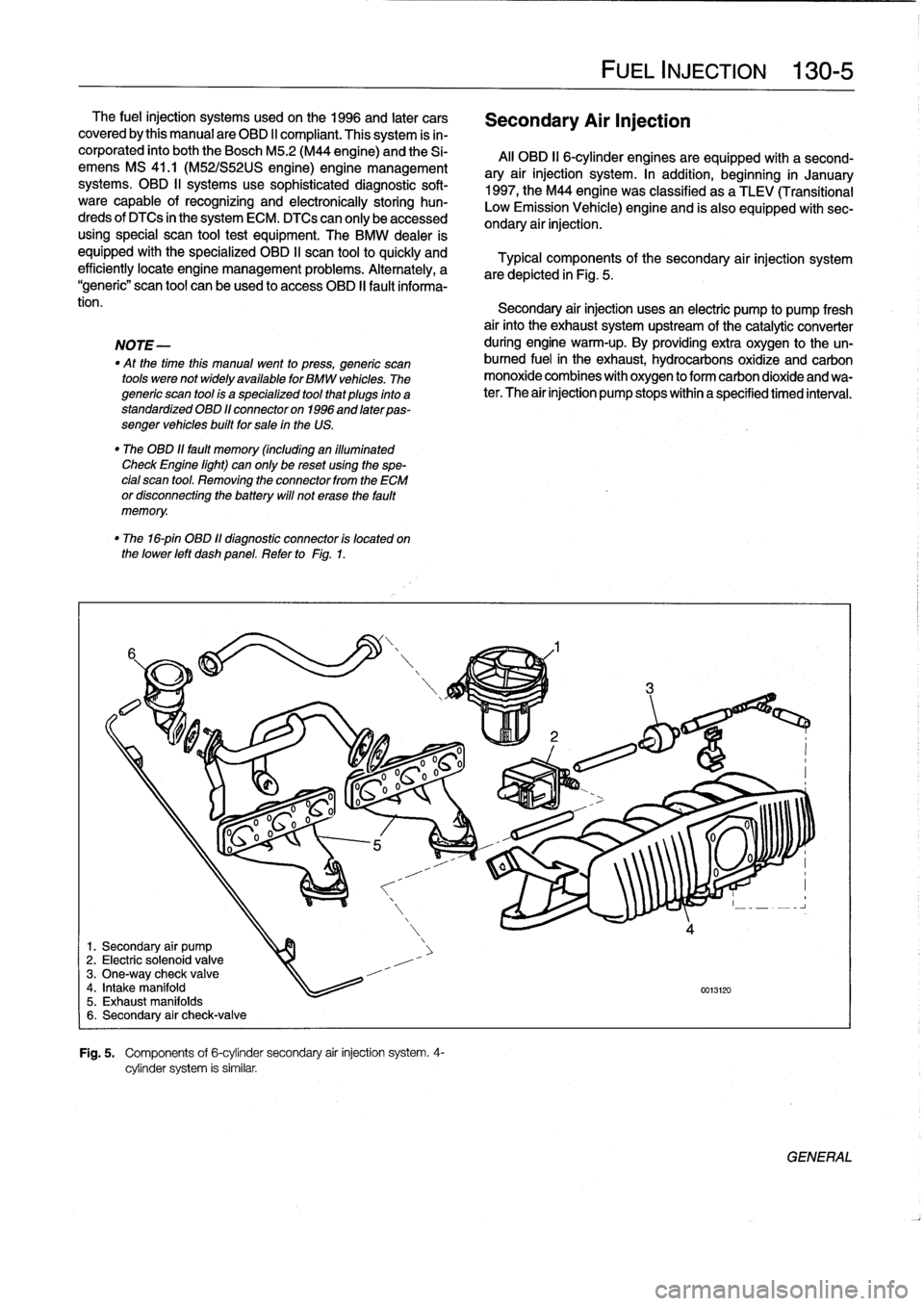
1
.
Secondary
air
pump
2
.
Electric
solenoid
valve
3
.
One-way
check
valve
4
.
Intake
manifold
5
.
Exhaust
manifolds
6
.
Secondary
air
check-valve
®
G~
i
o
o
0
0
G
0000
o
,-
00
~
1111111
in
,,
0
1--
a
Fig
.
5
.
Components
of
6-cylinder
secondary
air
injection
system
.
4-
cylinder
system
is
similar
.
Secondary
AirInjection
FUEL
INJECTION
130-
5
All
OBD
II
6-cylinder
engines
are
equípped
with
asecond-
ary
air
injection
system
.
In
addition,
beginning
in
January
1997,
the
M44
engine
was
classified
as
a
TLEV
(Transitional
Low
Emission
Vehicle)
engine
and
is
also
equipped
with
sec-
ondary
air
injection
.
Typical
components
of
the
secondary
air
injection
system
are
depicted
in
Fig
.
5
.
Secondary
air
injection
usesan
electric
pump
to
pump
fresh
air
finto
the
exhaust
systemupstream
of
the
catalytic
converter
during
engine
warm-up
.
By
providing
extra
oxygen
to
the
un-
burned
fuel
in
the
exhaust,
hydrocarbons
oxidize
and
carbon
monoxide
combines
with
oxygen
to
form
carbon
dioxide
andwa-
ter
.
The
air
injection
pump
stops
within
a
specified
timed
intenral
.
4
0013120
GENERAL
Page 215 of 759
GENERAL
..
.
.
.
.
.
.
.
.
.
.
.
.
.
......
.
......
210-1
CLUTCH
MECHANICAL
.
.
.
.
.
...
.
.....
.
.
210-3
CLUTCH
HYDRAULICS
.
.
.
.............
210-1
Clutch,
removing
.
.
.
.
.
.
.
.
.
.
.
.
.
.
.
.
...
.
.
.
.
210-4
Clutch,inspecting
and
installing
.
.
.
.
.
.
.
.
.
.
.
.210-5Clutch
hydraulic
system,
Transmission
pilot
bearing,replacing
.
.
.
.
...
210-6
bleeding
and
flushing
.
.
.
.
.
.......
.
.....
210-2
Clutch
master
cylinder,
replacing
..
.
.
.
.
.
...
210-2
Table
Clutch
slave
cylinder,
replacing
...
.
.
.
.
.
.
.
.
210-3
a
.
Clutch
Disc
Diameter
.............
..
..
.
......
210-3
GENERAL
CLUTCH
HYDRAULICS
This
repair
group
covers
replacement
of
the
clutch
mechan-
The
Clutch
is
hydraulically
actuated
by
the
master
and
slave
¡cal
and
hydraulic
components
.
Special
tools
may
be
required
cylinders
.
Clutch
disc
wear
is
automatically
taken
upby
the
for
some
of
the
procedures
.
Read
the
procedure
through
be-
pushrod
travelof
the
slave
cylinder,
making
periodic
adjust-fore
beginning
a
job
.
ments
unnecessary
.
NOTE-
See200
Transmission-General
for
transmission
applicatíon
information
.
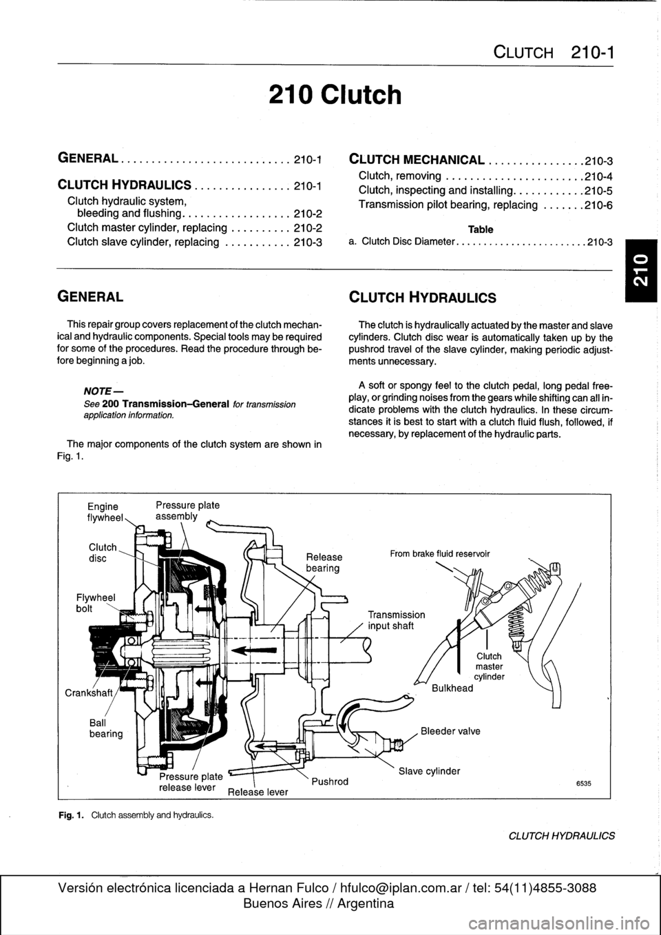
The
major
components
of
the
clutch
system
are
shown
in
Fig
.
1
.
Engine
Pressure
plate
flywheel,,
assembly
Clutch
Flywheel
bolt
Pressure
plate
release
lever
Release
lever
Fig
.
1
.
Clutch
assembly
and
hydraufcs
.
210
Clutch
Release
bearing
Pushrod
A
soft
or
spongy
feel
to
the
clutchpedal,
long
pedal
free-
play,
or
grinding
noises
from
thegears
while
shifting
can
all
in-
dicate
problems
with
the
Clutch
hydraulics
.
In
these
circum-
stances
it
is
best
to
start
with
a
clutch
fluid
flush,
followed,
if
necessary,
byreplacement
of
the
hydraulic
parts
.
From
brake
fluid
reservoir
CLUTCH
210-1
0
0
Transmission
inputshaft
Clutch
master
cylinder
Bulkhead
Slave
cylinder
6535
CLUTCH
HYDRAULICS
Page 223 of 759
Selector
shaft
seal,
replacing
(transmission
instalied)
1
.
Raise
and
safely
support
vehicle
to
access
drain
plug
.
2
.
Support
transmission
with
transmission
jack
.
3
.
Remove
driveshaft
.
See
260
Driveshaft
.
4
.
Remove
transmission
crossmember
and
tilt
down
rear
of
transmission
.
CA
UTION--
Tilting
the
engine
to
lower
the
transmission
can
lead
to
damage
to
various
cgmponents
due
to
lack
of
clearance
.
-On
cars
with
AST
(traction
control)
remove
throt-
tle
body
before
tiltlng
engine
.
-Remove
brake
fluid
reservoir
lf
necessary
.
Locking
pin
á
Locking
clip
8
.
Reinstall
shift
linkage
to
selectorshaft
.
7
.
Coat
new
seal
with
transmission
fluid
.
Drive
new
seal
in
flush
with
housing
.
Use
BMW
special
seal
installation
tool
no
.
23
2
260
orequivalent
and
a
soft-faced
(plastic)
hammer
.
See
Fig
.
4
.
9
.
Fiaise
transmission
and
reinstall
crossmember
.
MANUAL
TRANSMISSION
230-
3
Seal
Selector
_
shaft
5
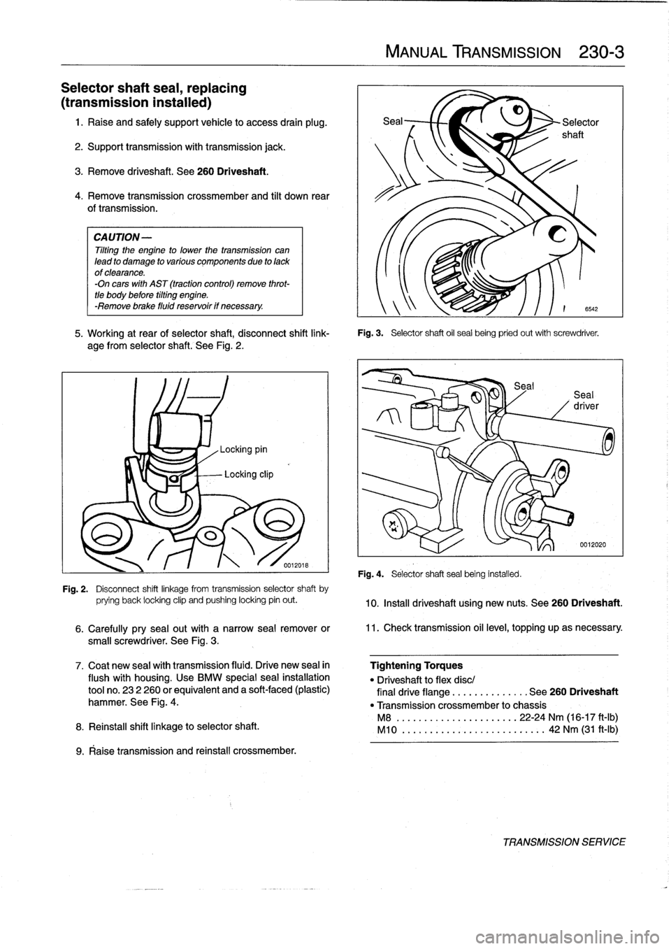
.
Working
at
rear
of
selector
shaft,
disconnect
shift
link-
Fig
.
3
.
Selector
shaft
oil
sea¡
being
pried
out
with
screwdriver
.
age
from
selectorshaft
.
See
Fig
.
2
.
Fig
.
4
.
Selector
shaftseal
being
installed
.
6542
0012020
Fig
.
2
.
Disconnect
shift
linkage
from
transmission
selector
shaft
by
prying
back
locking
clip
and
pushing
locking
pin
out
.
10
.
Install
driveshaft
using
new
nuts
.
See260
Driveshaft
.
6
.
Carefully
pry
sea¡
out
with
a
narrow
seal
remover
or
11
.
Check
transmission
oil
level,
topping
upas
necessary
.
small
screwdriver
.
See
Fig
.
3
.
Tightening
Torques
"
Driveshaftto
flex
disc/
final
drive
flange
..............
See
260
Driveshaft
"
Transmission
crossmember
to
chassis
M8
........
..
.
...
........
22-24
Nm
(16-17
ft-1b)
M10
........
.
.
...
...
.
.........
42
Nm
(31
ft-Ib)
TRANSMISSIONSERVICE