sensor BMW 318i 1998 E36 Workshop Manual
[x] Cancel search | Manufacturer: BMW, Model Year: 1998, Model line: 318i, Model: BMW 318i 1998 E36Pages: 759
Page 439 of 759
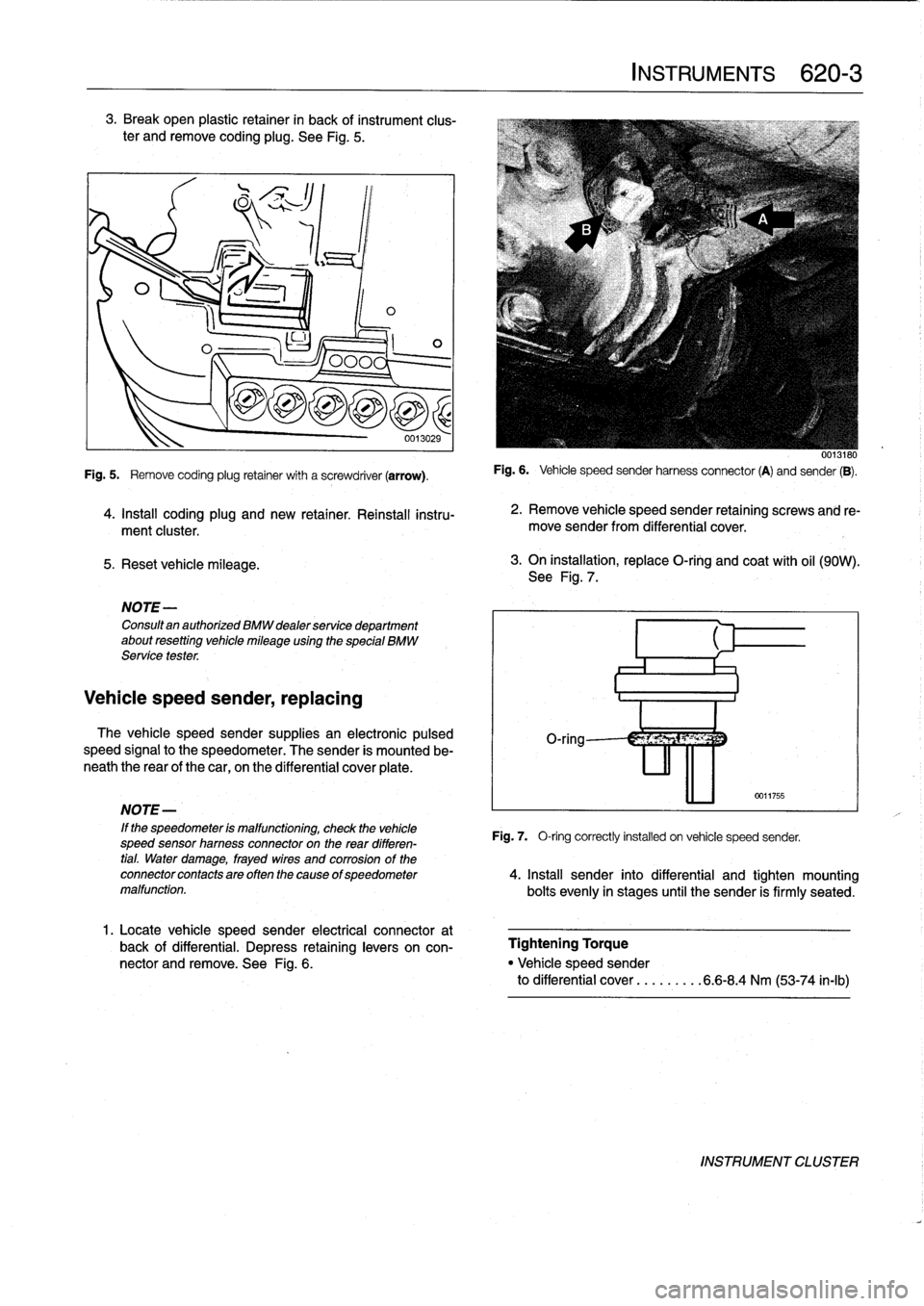
3
.
Break
open
plastic
retainer
in
back
of
instrument
clus-
ter
andremove
coding
plug
.
See
Fig
.
5
.
5
.
Reset
vehicle
mileage
.
1
ILO
NOTE-
Consultan
authorized
BMW
dealer
service
department
about
resetting
vehicle
mileage
using
the
special
BMW
Service
tester
.
Vehicle
speed
sender,
replacing
0
0013029
Fig
.
5
.
Remove
coding
plug
retainer
with
a
screwdriver
(arrow)
.
4
.
Install
coding
plug
and
new
retainer
.
Reinstall
instru-
ment
cluster
.
The
vehicle
speed
sender
supplies
an
electronic
pulsed
speed
signal
to
the
speedometer
.
The
sender
is
mounted
be-
neath
the
rear
of
the
car,
on
the
differential
cover
plate
.
1
.
Locate
vehicle
speed
sender
electrical
connector
at
back
of
differential
.
Depress
retaininglevers
on
con-
nector
and
remove
.
See
Fig
.
6
.
INSTRUMENTS
620-
3
0013180
Fig
.
6
.
Vehicle
speed
sender
harnessconnector
(A)
and
sender
(B)
.
2
.
Remove
vehicle
speed
sender
retaining
screws
and
re-
move
sender
from
differential
cover
.
3
.
On
installation,
replace
O-ring
and
coat
with
oil
(90W)
.
See
Fig
.
7
.
0011755
NOTE-
'
If
the
speedometer
is
malfunctioning,
check
the
vehicle
Fig
.
7,
O-ring
correctly
installed
on
vehicle
speed
sender,
speed
sensor
hamess
connectoron
the
rear
differen-
tial
.
Water
damage,
frayed
wires
and
corrosion
of
the
connectorcontactsareoftenthecause
ofspeedometer
4
.
Insta¡¡
sender
into
differential
and
tighten
mounting
malfunction
.
bolts
evenly
in
stages
until
the
sender
is
firmly
seated
.
Tightening
Torque
"
Vehicle
speed
sender
to
differential
cover
...
.
.....
6
.6-8
.4
Nm
(53-74
in-lb)
INSTRUMENT
CLUSTER
Page 447 of 759
GENERAL
E36
cars
are
equipped
with
integrated
automatic
heating
and
air
conditioning
systems
.
Many
of
the
procedures
given
in
this
repair
group
require
that
the
A/C
refrigerant
charge
be
evacuated
using
specialized
equipment
.
See
A/C
System
Warningsand
Cautions
later
in
this
repair
group
.
HEATER
AND
CONTROLS
Blower
motor,
removing
and
installing
NOTE-
On
6-cylinder
cars,
the
plastic
top
enginecover
and
fuel
rail
covermustbe
removed
.
The
fuel
injectorhamess
re-
taining
screws
must
be
removed
and
the
harness
set
aside
.
The
engine
control
module
(ECM)
cover
must
be
removed,
the
control
unit
connectors
unplugged
and
the
harness
pulled
out
of
the
way
.
See
130
Fuel
Injection
.
1
.
Disconnect
negative
(-)
cable
from
battery
.
2
.
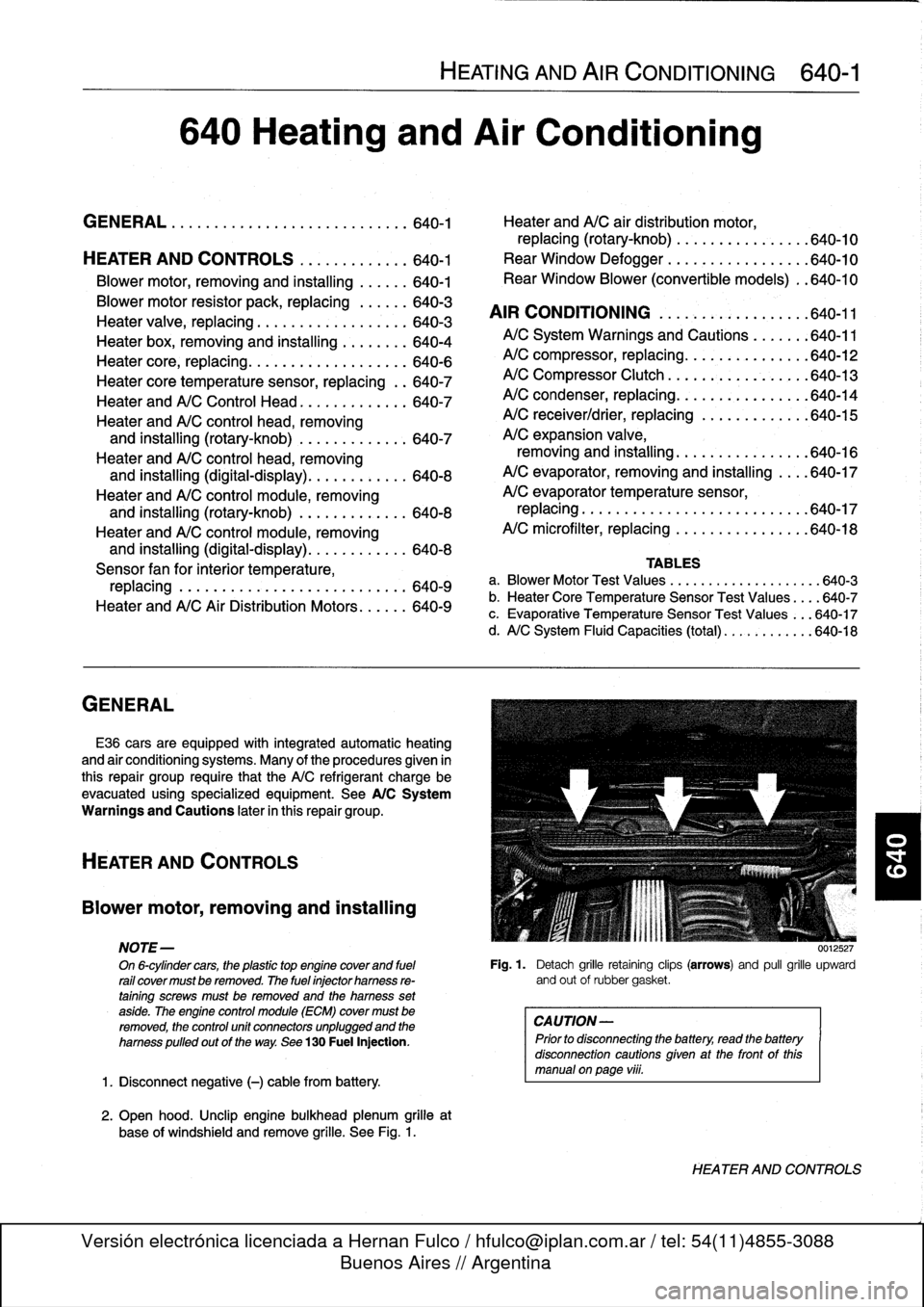
Open
hood
.
Unclip
engine
bulkhead
plenum
grille
at
base
of
windshíeld
and
remove
grille
.
See
Fig
.
1
.
HEATING
AND
AIR
CONDITIONING
640-1
640
Heating
and
Air
Conditioning
GENERAL
.
...
.
....
.
.
.
.
.
.
.
.
.
.......
.
.
.
640-1
Heater
andA/C
air
distribution
motor,
replacing(rotary-knob)
.
.
...
.
.
.
.......
.
640-10
HEATER
AND
CONTROLS
.
.....
.
.
.
.
.
.
.640-1
Rear
Window
Defogger
.
.
.
.
.
.
.
.
.
.
...
.
.
.
640-10
Blower
motor,
removing
and
installing
.
.
.
.
.
.
640-1
Rear
Window
Blower
(convertible
models)
.
.640-10
Blowermotor
resistor
pack,
replacing
.
.
.
.
.
.
640-3
AIR
CONDITIONING
.
.
.
.
.
.
.
.
.
.
.
.
.
.
.
.
.
.
640-11
Heater
valve,
replacing
...........
.
.
.
.
.
.
.
640-3
Heater
box,
removing
and
installing
.
.
.
.
.
.
.
.
640-4
A/CSystem
Warnings
and
Cautions
.
.
.
.
.
.
:640-11
Heater
core,
replacing
.....
.
.
:
....
.
.
.
.
.
.
.
640-6
A/C
compressor,
replacing
.
.
::.
:
:
.
.
.
.
.
.
.
.640-12
Heater
core
temperature
sensor,
replacing
.
.
640-7
A/C
Compressor
Clutch
.
.
.
.
.
.
.
:
.
.
.
.
.
.
.
.
.
640-13
Heater
andA/C
Control
Head
.
.
....
.
.....
.
640-7
A/C
condenser,
replacing
.
.
.
.
.
.
.
.
.
.
.
.
.
.
.
.
640-14
Heater
andA/C
control
head,
removing
A/C
receiver/drier,
replacing
.
.
.
.
.
.
.
.
.
.
.
.
.
640-15
and
installing
(rotary-knob)
.
.
....
.
......
640-7
A/C
expansion
valve,
Heater
andA/C
control
head,
removing
removing
and
installing
...
.
.....
.
.
.
.
.
.
.
640-16
and
installing
(digital-display)
.
.....
.
.....
640-8
A/C
evaporator,
removing
and
installing
.
.
..
640-17
Heater
andA/C
control
module,removing
A/C
evaporator
temperature
sensor,
and
installing
(rotary-knob)
.
.
...
.
.
.
.
.
.
.
.
640-8
replacing
.
.
.
.
.
.
..............
.
.
.
.
.
..
640-17
Heater
andA/C
control
module,removing
A/C
microfilter,
replacing
......
.
....
.
.
.
..
640-18
and
installing
(digital-display)
.
...
.
.
.
.
.
...
640-8
Sensor
fan
for
interior
temperature,
TABLES
replacing
.
.
.
....
.
.
.
.
.
.
.
.
.
.
.
.
.
.
.
.
.
.
.
.
640-9
a
.
Blower
Motor
Test
Values
.........
...
.
.
......
640-3
Heater
andA/C
AirDistribution
Motors
.
.
.
.
.
.
640-9
b
.
Heater
Core
Temperature
Sensor
Test
Values
...
.640-7
c
.
Evaporative
Temperature
Sensor
Test
Values
...
640-17
d
.
A/C
System
Fluid
Capacities
(total)
..
..........
640-18
0012527
Fig
.
1
.
Detach
grille
retaining
clips
(arrows)
and
pull
grille
upward
and
out
of
rubbergasket
.
CAUTION-
Prior
to
disconnectiog
the
battery,
read
the
battery
disconnection
cautionsgiven
at
the
front
of
this
manual
onpage
viii
.
HEATER
AND
CONTROLS
Page 450 of 759
640-4
HEATING
AND
AIR
CONDITIONING
Heater
box,
removing
and
installing
The
heater
box,
located
underneath
thecenter
of
the
dash-
board,
houses
theheater
core,
the
A/C
evaporator,
and
asso-
ciated
sensors
and
actuators
.
Removal
of
theheater
box
requires
that
the
A/C
refrigerant
be
discharged
.
CAUTION-
"
Removing
the
heater
box
requires
evacuating
the
AIC
system
.
DO
NOT
attempt
this
procedure
without
proper
tools
and
training
.
"
Any
person
who
services
a
motor
vehicle
air
con-
ditioner
must,
by
law,
be
properly
trained
and
cer-
tified,
and
use
approved
refrigerant
recycling
equipment
.
Technicians
must
complete
an
EPA-
approved
recycling
course
to
be
certified
UU12639
Fig
.
10
.
Heater
core
mounting
nuts
at
left
sideof
bulkhead
(arrow)
.
1
.
Drain
engine
coolant
.
See
170
Radiator
and
Cooling
wiper
assembly
shown
removed
for
clarity
.
System
.
2
.
Remove
complete
dashboard
.
See513
Interior
Trim
.
3
.
Remove
blower
motoras
described
earlier
.
4
.
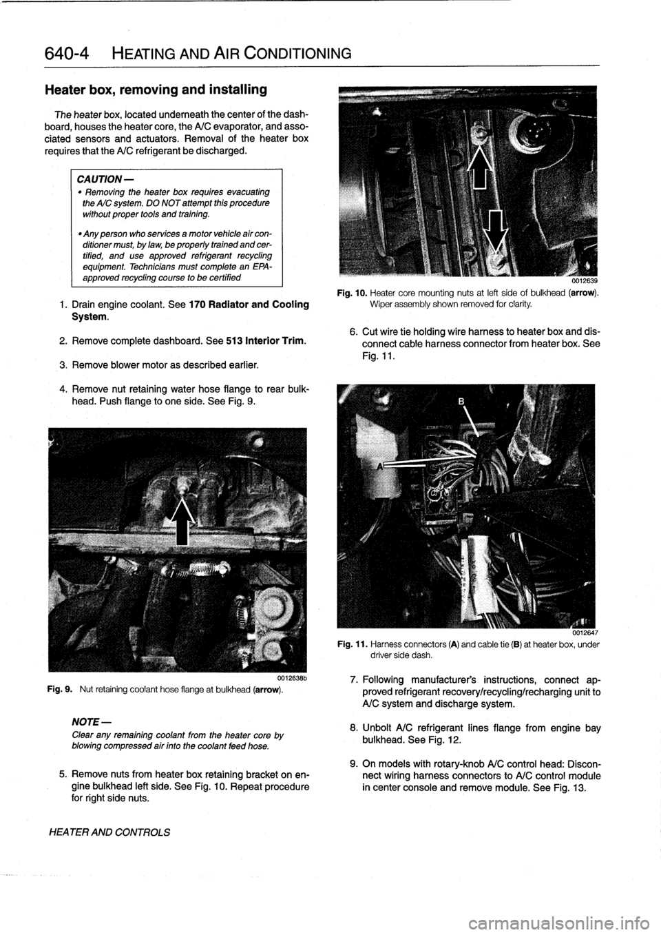
Remove
nut
retaining
water
hose
flange
to
rear
bulk-
head
.
I'ush
flange
to
one
side
.
See
Fig
.
9
.
Fig
.
9
.
Nut
retaining
coolant
hose
flangeat
bulkhead
(arrow)
.
NOTE-
Clear
any
remaining
coolant
from
the
heater
core
by
blowing
compressed
air
finto
the
coolant
feed
hose
.
HEATER
AND
CONTROLS
0012638b
6
.
Cut
wire
tie
holding
wire
harness
to
heater
box
and
dis-
connect
cable
harness
connector
from
heater
box
.
See
Fig
.
11
.
0012647
Fig
.
11
.
Harness
connectors
(A)
and
cable
tie
(B)
at
heaterbox,
under
driver
side
dash
.
7
.
Followingmanufacturer's
instructions,
connect
ap-
proved
refrigerant
recovery/recycling/recharging
unitto
A/C
system
and
discharge
system
.
8
.
Unbolt
A/C
refrigerantlines
flange
from
engine
bay
bulkhead
.
See
Fig
.
12
.
9
.
On
models
with
rotary-knob
A/C
control
head
:
Discon-
5
.
Remove
nuts
from
heater
box
retaining
bracket
on
en-
nect
wiring
harness
connectors
to
A/C
control
module
gine
bulkhead
left
side
.
See
Fig
.
10
.
Repeat
procedure
in
center
console
and
remove
module
.
See
Fig
.
13
.
for
right
side
nuts
.
Page 452 of 759
640-6
HEATING
AND
AIRCONDITIONING
Heater
core,replacing
1.
Drain
engíne
coolant
.
See170
Radiator
and
Cooling
System
.
WARNING
-
Allow
the
cooling
system
to
cool
before
opening
or
drainíng
the
cooling
system
.
2
.
Remove
center
console
.
See
513
Interior
Trim
.
3
.
Remove
Multi-Information
Display
(MID)
module
.
See
620
Instruments
.
4
.
Remove
lower
dash
panel
and
knee
bolster
on
driver
side
.
See
513
Interior
Trim
.
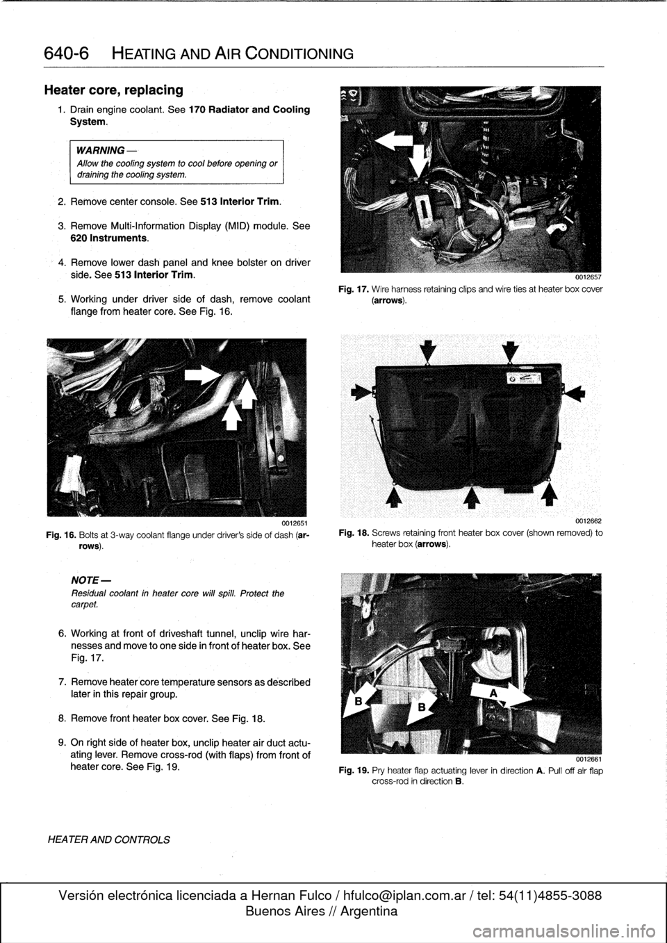
Fig
.
17
.
Wire
harness
retaining
clips
and
wire
ties
at
heater
box
cover
5
.
Working
under
driver
side
of
dash,
remove
coolant
(arrows)
.
flange
from
heater
core
.
See
Fig
.
16
.
0012651
Fig
.
16
.
Bolts
at
3-way
coolant
flange
under
driver's
side
of
dash
(ar-
rows)
.
NOTE-
Residual
coolant
in
heater
core
will
spill
.
Protect
thecarpet
.
6
.
Working
at
front
of
driveshaft
tunnel,
unclip
wire
har-
nesses
and
move
to
one
side
in
front
of
heater
box
.
See
Fig
.
17
.
7
.
Remove
heatercore
temperature
sensorsas
described
later
in
this
repair
group
.
8
.
Remove
front
heater
box
cover
.
See
Fig
.
18
.
9
.
On
right
side
of
heater
box,
unclip
heater
air
duct
actu-
ating
lever
.
Remove
cross-rod
(with
flaps)
from
frontof
heater
core
.
See
Fig
.
19
.
HEATER
AND
CONTROLS
0012662
Fig
.
18
.
Screws
retaining
front
heater
box
cover
(shown
removed)
to
heater
box
(arrows)
.
0012661
Fig
.
19
.
Pry
heater
flap
actuating
lever
in
direction
A
.
Pull
offair
flap
cross-rod
in
direction
B
.
Page 453 of 759
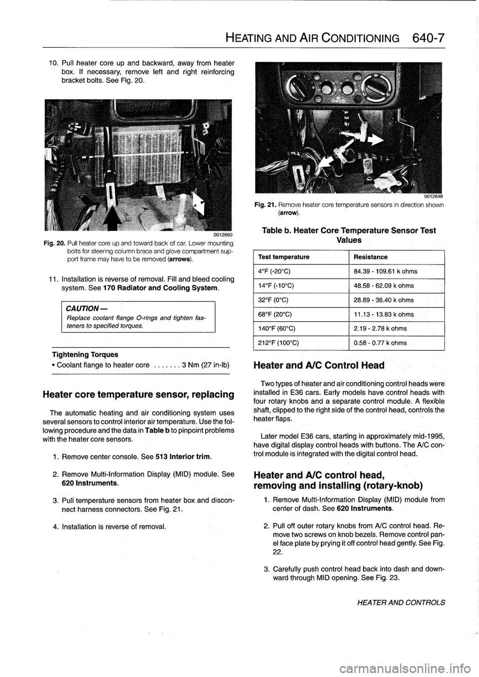
10
.
Pul¡
heater
core
up
and
backward,
away
from
heater
box
.
If
necessary,
remove
left
and
right
reinforcing
bracket
bolts
.
See
Fig
.
20
.
CAUTION-
Replace
coolant
flange
O-rings
and
tighten
fas-
teners
to
specified
torques
.
Tightening
Torques
1
.
Remove
center
console
.
See
513
Interior
trim
.
0012660
Fig
.
20
.
PA
heater
core
upand
towardback
of
car
.
Lower
mounting
bolts
for
steering
column
brace
and
glove
compartment
sup-
port
frame
may
have
to
be
removed
(arrows)
.
11
.
Installation
is
reverse
of
removal
.
Fill
and
bleed
cooling
system
.
See
170
Radiator
and
Cooling
System
.
"
Coolant
flange
to
heater
core
.
..
....
3
Nm
(27
in-lb)
Heater
andA/C
Control
Head
Heatercore
temperature
sensor,
replacing
The
automatic
heating
and
air
conditioning
systemuses
severa¡
sensors
to
control
interior
air
temperature
.
Use
the
fol-
lowing
procedure
and
the
data
in
Table
b
to
pinpoint
problems
with
theheater
core
sensors
.
2
.
Remove
Multi-Information
Display
(MID)
module
.
See
6201nstruments
.
HEATING
AND
AIR
CONDITIONING
640-7
0012648
Fig
.
21
.
Remove
heatercore
temperaturesensors
in
direction
shown
(arrow)
.
Table
b
.
Heater
CoreTemperatureSensor
Test
Values
Test
temperature
Resistance
4°F
(-20°C)
84
.39
-
109
.61
k
ohms
14
°
F
(-10°C)
48
.58
-
62
.09
k
ohms
32°F
(0°C)
28
.89
-
36
.40
k
ohms
68°F
(20°C)
11
.13
-
13
.83
k
ohms
140°F
(60°C)
2
.19
-
2
.78
k
ohms
212°F
(100°C)
0
.58
-
0
.77
k
ohms
Two
types
of
heater
and
aír
conditioning
control
heads
viere
installed
in
E36
cars
.
Early
models
have
control
heads
with
four
rotary
knobs
and
a
separate
control
module
.
A
flexible
shaft,
clipped
to
the
right
sideof
the
control
head,
controls
the
heater
flaps
.
Later
model
E36
cars,
starting
in
approximately
mid-1995,
have
digital
display
control
heads
with
buttons
.
The
A/C
con-
trol
module
is
integrated
with
the
digital
control
head
.
Heater
and
A/C
control
head,
removing
and
installing
(rotary-knob)
3
.
Pul¡
temperature
sensors
from
heater
box
and
discon-
1
.
Remove
Multi-Information
Display
(MID)
module
from
nect
harness
connectors
.
See
Fig
.
21
.
center
of
dash
.
See
620
Instruments
.
4
.
Installation
is
reverse
of
removal
.
2
.
Pul¡
off
outer
rotary
knobs
from
A/C
control
head
.
Re-
move
two
screwsonknob
bezels
.
Remove
control
pan-
el
face
plate
by
prying
it
off
control
head
gently
.
See
Fig
.
22
.
3
.
Carefully
push
control
head
back
into
dash
and
down-
ward
through
MID
opening
.
See
Fig
.
23
.
HEATER
AND
CONTROLS
Page 455 of 759
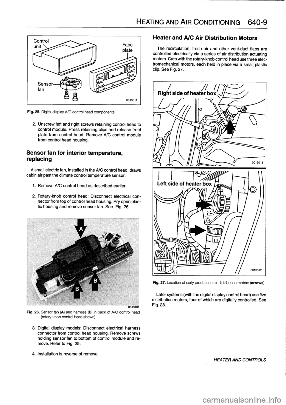
Sensor
fan
Fig
.
25
.
Digital
display
A/C
control
head
components
.
2
.
Unscrew
left
and
right
screws
retaining
control
head
to
control
module
.
Press
retaining
clips
and
release
front
plate
from
control
head
.
Remove
A/C
control
module
from
control
head
housing
.
Sensor
fan
for
interior
temperature,
repiacing
A
small
electricfan,installed
in
the
A/C
control
head,
draws
cabin
air
past
the
climate
control
temperature
sensor
.
1.
Remove
A/C
control
head
as
described
earlier
.
2
.
Rotary-knob
control
head
:
Disconnect
electrical
con-
nector
from
top
of
control
head
housing
.
Pry
open
plas-
tic
housing
and
remove
sensor
fan
.
See
Fig
.
26
.
0013181
Fig
.
26
.
Sensor
fan
(A)
and
harness
(B)
in
back
of
A/C
control
head
(rotary-knob
control
head
shown)
.
3
.
Digital
display
models
:
Disconnect
electrical
harness
connector
from
control
head
housing
.
Remove
screws
holding
sensor
fan
to
bottom
of
control
moduleand
re-
move
.
Refer
to
Fig
.
25
.
4
.
Installation
is
reverse
of
removal
.
HEATING
AND
AIR
CONDITIONING
640-
9
Heater
and
A/C
Air
Distribution
Motors
The
recirculation,
fresh
air
and
othervent-duct
flaps
are
controlled
electrically
via
a
series
of
air
distribution
actuating
motors
.
Cars
with
the
rotary-knob
control
head
use
three
elec-
tromechanical
motors,
each
held
in
place
via
a
small
plastic
clip
.
See
Fig
.
27
.
Rightside
of
heater
box
l
Fig
.
27
.
Location
of
early
production
air
distribution
motors
(arrows)
.
Later
systems
(with
the
digital
display
control
head)
use
five
distribution
motors,
four
of
which
are
digítally
controlled
.
See
Fig
.
28
.
HEATER
AND
CONTROLS
Page 461 of 759
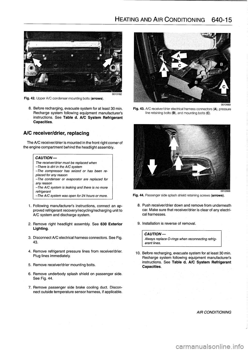
Fig
.
42
.
Upper
A/C
condensermounting
bolts
(arrows)
.
8
.
Before
recharging,
evacuate
system
for
at
least
30
min
.
Recharge
system
following
equipment
manufacturer's
instructions
.
See
Table
d
.
A/C
System
Refrigerant
Capacities
.
A/C
receiver/drier,
replacing
The
A/C
receiver/drier
is
mounted
in
the
front
right
cornee
of
the
engine
compartment
behind
the
headlight
assembly
.
CAUTION-
The
receiver/drier
must
be
replaced
when
-There
is
dirt
in
the
AIC
system
-The
compressor
has
seized
or
has
been
re-
placed
for
any
reason
-The
condenser
or
evaporator
are
replaced
for
any
reason
-The
AIC
system
is
leaking
and
there
is
no
more
refrigerant
-The
AIC
system
was
open
for
24
hours
or
more
.
1
.
Following
manufacturer's
instructions,
connectan
ap-
proved
refrigerant
recovery/recycling/recharging
unit
to
A/C
system
and
discharge
system
.
2
.
Remove
right
headlight
assembly
.
See
630
Exterior
Lighting
.
CAUTION-
3
.
Disconnect
A/C
electrical
harness
connectors
.
See
Fig
.
Always
replaceO-rings
when
reconnecting
refrig-
43
.
erant
lines
.
4
.
Remove
refrigerant
pressure
lines
from
receiver/drier
.
Plug
lines
immediately
.
5
.
Remove
receiver/drier
mounting
bolts
.
0013182
6
.
Remove
underbody
splash
shield
on
passenger
side
.
See
Fig
.
44
.
7
.
Remove
passenger
side
brake
cooling
duct
.
Discon-
nect
outside
temperature
sensor
harness,
if
applicable
.
HEATING
AND
AIR
CONDITIONING
640-15
0012669
Fig
.
43
.
A/
C
receiver/drier
electrical
harness
connectors
(A),
pressure
line
retaining
bolts
(B),
andmounting
bolts
(C)
.
0012668
Fig
.
44
.
Passenger
sidesplash
shield
retaining
screws
(arrows)
.
8
.
Push
receiver/drier
down
andremove
from
underneath
car
.
Make
sure
that
receiver/drier
is
clear
of
any
electri-
cal
harnesses
.
9
.
Installation
is
reverse
of
removal
.
10
.
Before
recharging,
evacuate
system
for
at
least
30
min
.
Recharge
system
following
equipment
manufacturer's
instructions
.
See
Table
d
.
A/C
System
Refrigerant
Capacities
.
AIR
CONDITIONING
Page 463 of 759
CAUTION
-
Always
replace
O-rings
when
reconnecting
refrig-
erant
fines
.
9
.
Before
recharging,
evacuate
system
for
at
least
30
min
.
Recharge
system
following
equipment
manufacturer's
instructions
.
See
Table
d
.
A/C
System
Refrigerant
Capacities
.
A/C
evaporator,
removing
and
installing
1
.
Followingmanufacturer's
instructions,
connectanap-proved
refrigerant
recovery/recycling/recharging
unit
to
A/C
system
and
discharge
system
.
2
.
Remove
complete
heater
boxas
described
earlier
.
3
.
Remove
expansion
valve
as
described
earlier
.
4
.
Unfasten
evaporator
sensor
electrical
harness
connec-
tor
and
puli
out
sensor
from
ieft
side
of
heater
box
.
See
Fig
.
50
.
Fig
.
49
.
Pull
out
evaporator
sensor
from
housing
in
direction
of
arrow
.
5
.
Remove
rear
heater
box
cover
.
6
.
Remove
clips
retaining
lower
evaporator
housingcover
.
Tilt
outheater
core,
then
pull
evaporator
out
of
housing
.
7
.
Installation
is
reverse
of
removal
.
CAUTION
-
Always
reptace
O-rings
when
reconnecting
refrtg-
erant
fines
.
8
.
Before
recharging,
evacuate
system
for
at
least
30
min
.
Recharge
system
following
equipment
manufacturer's
instructions
.
See
Table
d
.
A/C
System
Refrigerant
Capacities
.
HEATING
AND
AIR
CONDITIONING
640-17
8
.
Installation
is
reverse
of
removal
.
A/C
evaporator
temperature
sensor,
replacing
ou12b46
The
evaporator
temperature
sensor
is
mounted
in
the
left
(driver)
side
of
theheater
box
behind
thecenter
console
.
1
.
Remove
lower
dash
panel
and
knee
boister
on
driver
side
.
See
513
Interior
Trim
.
2
.
Remove
left
footwell
ventilation
duct
byremoving
re-
taining
rivet
in
bottom
of
duct
.
Pull
it
down
and
away
from
heater
box
.
See
Fig
.
50
.
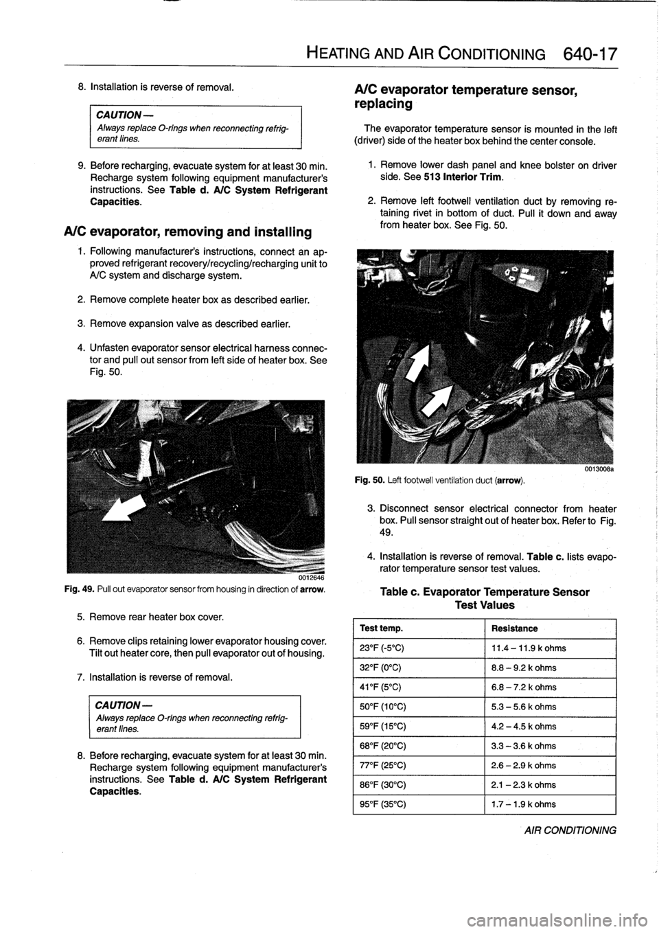
Fig
.
50
.
Left
footwellventilatíon
duct
(arrow)
.
0o1300ba
3
.
Disconnect
sensor
electrical
connector
from
heater
box
.
Pull
sensor
straight
out
of
heater
box
.
Refer
to
Fig
.
49
.
4
.
Installation
is
reverse
of
removal
.
Table
c
.
lists
evapo-
rator
temperature
sensor
test
values
.
Tablec
.
Evaporator
Temperature
Sensor
Test
Values
Test
temp
.
Resistance
23°F
(-5°C)
11
.4
-11
.9
k
ohms
32°F
(0°C)
8
.8
-
9
.2
k
ohms
41
°F
(5°C)
6
.8
-
7
.2
k
ohms
50°F
(10°C)
5
.3-5
.6
k
ohms
59
°
F
(15°C)
4
.2
-4
.5
k
ohms
68°F
(20°C)
3
.3
-
3
.6
k
ohms
77°F
(25°C)
2
.6-2
.9
k
ohms
86°F
(30°C)
2
.1
-
2
.3
k
ohms
95°F
(35°C)
1
.7
-1
.9
k
ohms
AIR
CONDITIONING
Page 477 of 759
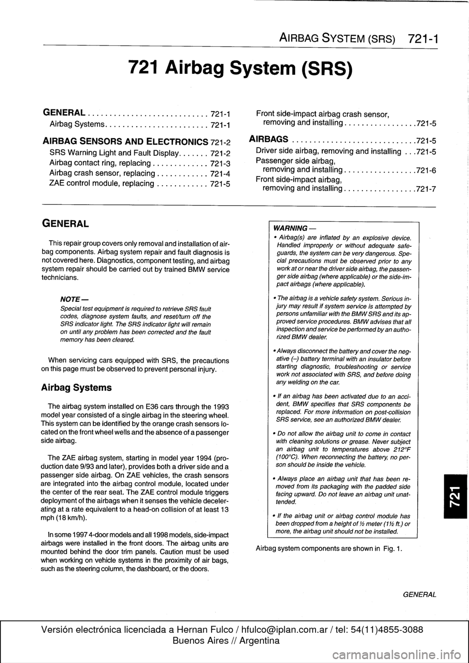
721
Airbag
System
(SRS)
Airbag
Systems
.......
.
...
.
.
.
.
.
....
.
.
.
.
721-1
AIRBAG
SENSORS
AND
ELECTRONICS
721-2
SRS
Warning
Light
and
Fault
Display
.
.
.
.
.
..
721-2
Airbagcontact
ring,
replacing
........
.
.
.
.
.
721-3
Airbag
crash
sensor,replacing
..
.
....
.
...
.
721-4
ZAE
control
module,
replacing
.
.
.
.........
721-5
GENERAL
This
repair
group
covers
only
removal
and
installation
of
air-
bag
components
.
Airbag
system
repair
and
fault
diagnosis
is
not
covered
here
.
Diagnostics,
component
testing,
and
airbag
system
repair
should
be
carried
out
by
trained
BMW
service
technicians
.
NOTE-
Special
test
equipment
is
required
to
retrieve
SRS
fault
codes,
diagnose
system
faults,
and
resetltum
off
the
SRS
indicator
light
.
The
SRS
indicator
light
will
remain
on
until
any
problem
has
been
corrected
and
the
fault
memory
has
been
cleared
.
When
servicing
cars
equipped
with
SRS,
the
precautions
on
this
page
mustbeobserved
to
prevent
personal
injury
.
Airbag
Systems
The
airbag
system
installed
on
E36
cars
through
the
1993
model
year
consisted
of
a
single
airbag
in
the
steering
wheel
.
This
systemcan
be
identified
by
the
orange
crash
sensors
lo-
cated
on
the
front
wheel
wells
and
the
absence
of
a
passenger
side
airbag
.
The
ZAE
airbag
system,
starting
in
model
year
1994
(pro-
duction
date9/93
and
later),
provides
both
a
driver
side
and
a
passenger
sideairbag
.
On
ZAE
vehicles,
the
crash
sensorsare
integrated
into
the
airbag
control
module,
located
under
thecenter
of
the
rear
seat
.
The
ZAE
control
module
triggers
deployment
of
the
airbags
When
it
sensos
the
vehicle
deceler-
ating
at
a
rate
equivalent
to
a
head-on
collisionof
at
least
13
mph
(18
km/h)
.
In
some
1997
4-door
models
and
all
1998
models,
side-impact
airbags
were
installed
in
the
front
doors
.
The
airbag
units
are
mounted
behindthe
door
trim
panels
.
Caution
mustbeused
when
working
on
vehicle
systems
in
the
proximity
of
air
bags,
such
as
the
steering
column,
the
dashboard,
or
the
doors
.
AIRBAG
SYSTEM
(SRS)
721-1
GENERAL
.
.
.
.
.
.
.
.
.
.
.......
.
......
.
.
.
.
721-1
Front
side-impact
airbag
crash
sensor,
removing
and
installing
....
.
.....
.
.....
.
721-5
AIRBAGS
..............
.
.
.
.
.
.
.
.
.
.
.
.
.
.
.
721-5
Driver
side
airbag,
removing
and
installing
.
.
.
721-5
Passenger
side
airbag,
removing
and
installing
..............
.
.
.721-6
Front
side-impact
airbag,
removing
and
installing
.
.
.
.
.
.
.
.
.
.
......
.721-7
WARNING
-
"
Airbag(s)
are
inflated
byan
explosive
device
.
Handled
improperly
or
without
adequate
safe-
guards,
the
System
can
be
very
dangerous
.
Spe-
cial
precautions
must
be
observed
prior
to
any
work
ator
near
the
driverside
airbag,
the
passen-
ger
side
airbag
(where
applicable)
or
the
side-im-
pact
airbags
(where
applicable)
.
"
The
airbag
is
a
vehicle
safety
system
.
Serious
in-
jury
may
result
if
System
service
is
attempted
by
persons
unfamiliar
with
the
BMW
SRS
and
its
ap-
proved
service
procedures
.
BMW
advises
that
all
inspection
and
service
be
performed
by
an
autho-
rized
BMW
dealer
.
"
Always
disconnect
the
battery
and
cover
the
neg-
ative
()
battery
terminal
with
an
insulator
before
startingdiagnostic,
troubleshooting
or
service
worknot
associated
with
SRS,
and
before
doing
any
welding
on
the
car
.
"
If
an
airbag
has
been
activated
due
to
an
acci-dent,
BMW
specifies
that
SRS
components
be
replaced
.
For
more
information
on
post-collision
SRS
service,
see
an
authorized
BMW
dealer
.
"
Do
not
allow
the
airbag
unit
to
come
in
contact
with
cleaning
solutions
orgrease
.
Never
subject
an
airbag
unit
to
temperatures
aboye
212°F
(100°C)
.
When
reconnecting
the
battery,
no
per-
son
should
be
inside
the
vehicle
.
"
Always
place
an
airbag
unitthat
has
been
re-
moved
from
its
packaging
with
the
padded
sidefacing
upward
.
Do
not
leave
an
airbag
unlt
unat-
tended
.
"
!f
the
airbag
unit
or
airbag
control
modulehas
been
dropped
froma
height
of
!
1
2
meter
(1
Y2
ft.)
ormore,
theairbag
unit
should
not
be
installed
.
Aírbag
system
components
are
shown
in
Fig
.
1.
GENERAL
Page 478 of 759
721-2
AIRBAG
SYSTEM
(SRS)
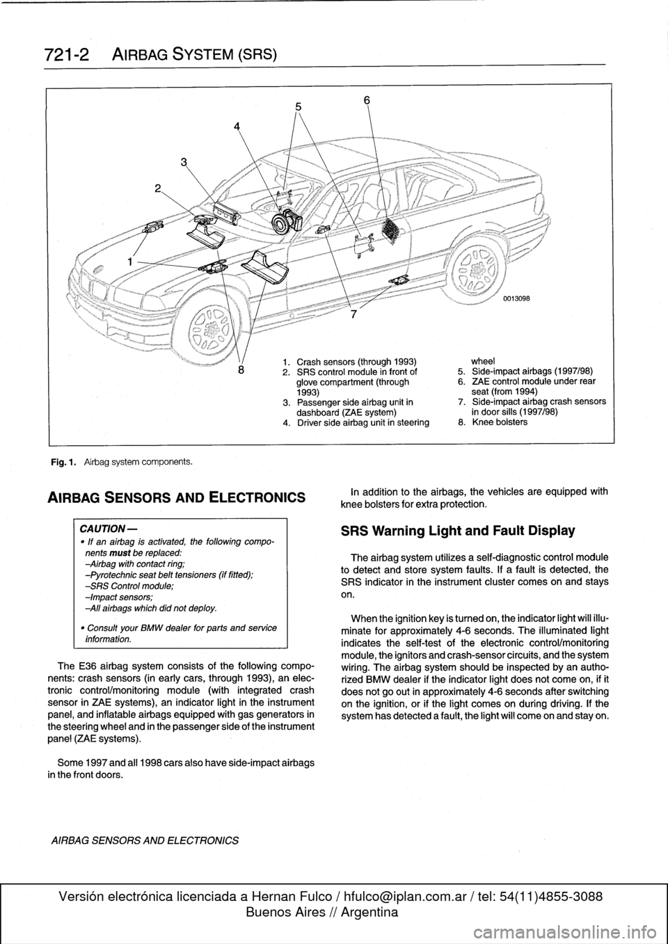
Fig
.
1
.
Airbag
system
components
.
AIRBAG
SENSORSAND
ELECTRONICS
CA
UTION-
"
If
an
airbag
is
activated,
the
following
compo-
nents
must
be
replaced
:
Airbag
with
contact
ring
;
-Pyrotechnic
seat
belt
tensioners
(if
fitted)
;
-SRS
Control
module
;
-Impact
sensors
;
All
airbags
which
did
not
deploy
.
"
Consult
your
BMW
dealer
for
parts
and
service
information
.
TheE36
airbag
system
consists
of
the
following
compo-
nents
:
crash
sensors
(in
earlycars,
through
1993),
an
elec-
tronic
control/monitoring
module
(with
integrated
crash
sensor
in
ZAE
systems),
an
indicator
light
in
the
instrument
panel,
and
inflatable
airbags
equipped
with
gas
generators
in
the
steering
wheel
and
in
the
passenger
side
of
the
instrument
panel
(ZAE
systems)
.
Some
1997
and
al¡
1998
carsalso
have
side-impact
airbags
in
the
front
doors
.
AIRBAG
SENSORS
AND
ELECTRONICS
1.
Crash
sensors
(through
1993)
wheel
2
.
SRS
control
module
in
front
of
5
.
Side-impact
airbags
(1997/98)
glove
compartment
(through
6
.
ZAE
control
module
under
rear
1993)
seat
(from
1994)
3
.
Passenger
side
airbag
unit
in
7
.
Side-impact
airbag
crash
sensors
dashboard
(ZAE
system)
in
door
silis
(1997/98)
4
.
Driver
side
airbag
unitin
steering
8
.
Knee
bolsters
In
addition
to
the
airbags,
the
vehicles
are
equipped
wíth
knee
bolsters
for
extra
protection
.
SRS
Warning
Light
and
Fault
Display
The
airbag
system
utilizes
a
self-diagnostic
control
module
to
detect
and
store
system
faults
.
If
a
fault
is
detected,
the
SRS
indicator
in
the
instrument
cluster
comes
on
and
stays
on
.
When
the
ignition
key
is
tumed
on,
the
indicator
light
will
illu-
minate
for
approximately
4-6
seconds
.
The
illuminated
light
indicates
the
self-testof
the
electronic
control/monitoring
module,
the
ignítors
and
crash-sensorcircuits,
and
the
system
wiring
.
The
airbag
system
should
be
inspected
byan
autho-
rized
BMW
dealer
if
the
indicator
light
does
not
come
on,
ifit
does
not
go
out
in
approximately
4-6
seconds
after
switching
onthe
ignition,
or
if
the
light
comes
on
during
driving
.
If
the
system
has
detected
a
fault,
the
light
will
come
on
and
stay
on
.