ignition BMW 318i 1998 E36 Workshop Manual
[x] Cancel search | Manufacturer: BMW, Model Year: 1998, Model line: 318i, Model: BMW 318i 1998 E36Pages: 759
Page 3 of 759
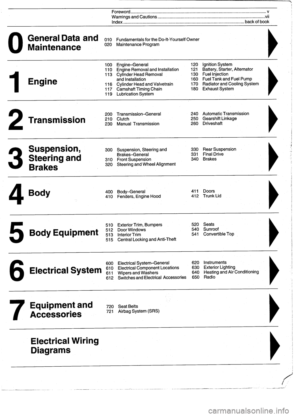
General
Data
and
010
FundamentalsfortheDo-lt-YourselfOwner
Maintenance
020
Maintenance
Program
Engine
Transmission
Suspension,
Steering
and
Brakes
4
Body
100
Engine-General
110
Engine
Removal
and
Installation
113
Cylinder
Head
Removal
and
Installation
116
Cylinder
Head
and
Valvetrain
117
Camshaft
Timing
Chain
119
Lubrication
System
200
Transmission-General
210
Clutch
230
Manual
Transmission
510
Exterior
Trim,
Bumpers
520
Seats
Bo
y
Equipment
512
DoorWTdws
540
nr
t
513
InteriorTrim
541
Convertible
Top
515
Central
Locking
and
Anti-Theft
600
Electrical
System-General
620
Instruments
Electrical
S
stem
610
Electrical
Component
Locations
630
Exterior
Lighting
611
Wipers
and
Washers
640
Heating
and
Air
Conditioning
6
612
Switches
and
Electrical
Accessories
650
Radio
Equipment
and
720
SeatBelts
Accessories
721
Airbag
System
(SRS)
Electrical
Wiring
Diagrams
Foreword
.
...
.
.
.
..................
.
.
.
.....
.
............
.
...
.
.
.
.
.
................
.
.
.
.....
.
......
.
................
.
.
.
.....
v
Warnings
and
Cautions
.....
.
...
.
.
.
.
.
..........
.
...
.
.
.
.
.
......
.
.........
.
.
.
...
.
.
.
......
.
.
.
.
.
............
.
.
.
.
.
.
.vii
Index
..............
.
.
.
.....
.
............
.
...
.
.
.
.
.
........
.
...
.
.
.
.
.
.......
.
......
.
...
.
.
.
.
.
.
.
........
.
.
.
..
back
of
book
300
Suspension,
Steering
and
330
RearSuspension
Brakes-General
331
Final
Drive
310
Front
Suspension
340
Brakes
320
Steering
and
Wheel
Alignment
400
Body-General
411
Doors
410
Fenders,
Engine
Hood
412
Trunk
Lid
120
Ignition
System
121
Battery,Starter,
Alternator
130
Fue¡
Injection
160
Fuel
Tank
and
Fuel
Pump
170
Radiator
and
Cooling
System180
Exhaust
System
240
Automatic
Transmission
250
Gearshift
Linkage
260
Driveshaft
Page 7 of 759
Please
read
these
warnings
and
cautions
before
proceeding
with
maintenance
and
repair
work
.
WARNING-
"
Friction
materials
(such
as
brake
pads
or
shorts
or
clutchdiscs)
contain
asbestos
fibers
or
other
friction
materials
.
Do
notcreate
"
See
also
Cautionson
page
viü
dustby
grinding,
sanding,
orby
cleaning
with
compressed
air
.
"
Some
repairs
may
be
beyond
your
capability
.
If
you
lack
the
Avoid
breathing
dust
.
Breathing
any
friction
material
dust
can
lead
skills,
tools
and
equipment,
or
a
suitable
workplace
for
any
proce-
to
serious
diseases
and
may
result
in
death
.
duredescribed
in
this
manual,
we
suggestyou
leave
such
repairs
"
Batteries
give
off
explosive
hydrogen
gas
during
charging
.
to
an
authorized
BMW
dealer
service
department
or
other
quali-
Keep
sparks,
lighted
matches
and
open
flame
away
from
the
top
fied
shop
.
of
the
battery
If
hydrogen
gas
escaping
from
the
cap
vents
is
"Do
not
re-use
any
fasteners
that
are
worn
or
deformed
in
normal
ignited,
it
will
ignite
gas
trapped
in
the
cells
and
cause
the
battery
use
.
Many
fasteners
are
designed
to
be
used
only
once
and
to
explode
.
become
unreliable
and
may
fail
when
used
a
second
time
.
This
"
Connect
and
disconnect
battery
cables,
jumper
cablesora
bat-
includes,
but
is
not
limited
to,
nuts,
bolts,
washers,
self-locking
nuts
or
bolts,
circlips
and
cotterpins
.
Always
replace
these
fasteners
with
new
parts
.
"Do
not
quick-charge
the
battery
(for
boost
starting)
for
longer
"
Never
work
under
a
lifted
car
unless
it
is
solidly
supportedon
than
one
minute
.
Wait
at
least
one
minute
before
boosting
the
bat-
stands
designed
for
the
purpose
.
Do
not
support
a
car
on
cinder
tery
a
second
time
.
blocks,
hollow
tiles
or
other
props
that
may
crumble
under
contin-
uous
load
.
Never
work
under
acar
that
is
supported
solely
by
a
"Do
not
allow
battery
charging
voltage
to
exceed
16
.5
volts
.
If
the
jack
.
Never
work
under
thecar
while
the
engine
is
running
.
battery
beginsproducing
gas
or
boiling
violently,
reduce
the
charg-
ing
rate
.
Boosting
a
sulfated
battery
at
a
high
charging
rate
can
"
If
you
are
going
to
work
under
acar
on
the
ground,
make
sure
cause
an
explosion
.
that
the
ground
is
level
.
Block
the
wheels
to
keep
the
carfrom
roll-
ing
.
Disconnect
the
battery
negative
(-)
terminal
(ground
strap)to
"
The
air-conditioning
system
is
filled
with
chemical
refrigerant,
prevent
others
from
starting
thecar
while
youare
under
it
.
which
is
hazardous
.
TheA/C
system
should
be
servicedonly
by
trained
technicians
using
approved
refrigerant
recovery/recycling
"
Never
run
the
engine
unless
the
work
area
is
well
ventilated
.
equipment,
trained
in
related
safetyprecautions,
and
familiar
with
Carbon
monoxide
kills
.
regulations
governing
the
discharging
and
disposal
of
automotive
"
Finger
rings,
bracelets
and
other
jewelry
shouldbe
removed
so
chemical
refrigerants
.
tery
charger
only
with
the
ignition
switched
off,
to
prevent
sparks
.
Do
not
disconnect
the
battery
while
the
engine
is
running
.
that
theycannot
cause
electrical
shorts,
get
caught
in
running
"
Do
not
expose
any
partof
the
A/Csystem
to
high
temperatures
machinery,
or
be
crushed
by
heavy
parts
.
suchas
open
flame
.
Excessiveheat
will
increase
system
pressure
"
Tie
long
hair
behind
your
head
.
Do
not
wear
a
necktie,
a
scarf,
and
may
cause
the
system
to
burst
.
loose
clothing,
or
a
necklace
when
you
work
near
machine
tools
or
"
Some
aerosol
tire
inflators
are
highly
flammable
.
Be
extremely
running
engines
.
If
your
hair,
clothing,
or
jewelry
were
to
get
caught
cautious
when
repairing
a
tire
that
may
havebeen
inflated
using
in
the
machinery,
severe
injury
could
result
.
an
aerosol
tire
inflator
.
Keep
sparks,
open
flame
or
other
sources
"
Do
not
attempt
to
work
onyourcar
if
you
do
not
feel
well
.
You
of
ignition
away
from
the
tire
repair
area
.
Inflate
and
deflate
the
tire
increase
the
danger
of
injury
toyourself
and
others
if
you
are
tired,
at
least
four
times
before
breaking
the
bead
from
therim
.
Com-
upset
or
have
takenmedication
or
any
other
substance
that
may
Pletely
remove
the
tire
from
the
rim
beforeattempting
any
repair
.
keep
you
from
being
fully
alert
.
"
Illuminate
your
work
areaadequately
but
safety
.
Use
a
portable
safety
light
for
working
inside
or
under
thecar
.
Make
surethe
bulb
is
enclosedbya
wire
cage
.
The
hot
filament
of
an
accidentally
bro-
ken
bulb
can
ignite
spilled
fuel
or
oil
.
"
Catch
draining
fuel,
oil,
orbrake
fluid
in
suitable
containers
.
Do
not
use
food
or
beverage
containers
that
mightmislead
someone
into
drínking
from
them
.
Store
flammable
fluids
away
from
fire
haz-
ards
.
Wipe
up
spills
at
once,
but
do
not
store
the
oily
rags,
which
can
ignite
and
burn
spontaneously
.
"
Always
observe
good
workshop
practices
.
Wear
goggles
when
youoperate
machine
tools
or
work
with
battery
acid
.
Gloves
or
other
protectioeclothing
should
be
worn
whenever
thejob
requires
working
with
harmful
substances
.
"
Greases,
lubricants
and
other
automotive
chemicals
contain
toxic
substances,
many
of
which
are
absorbed
directly
through
the
skin
.
Read
the
manufacturer's
instructions
and
warnings
carefully
.
Use
hand
andeye
protection
.
Avoid
direct
skin
contact
"
Cars
covered
by
this
manual
are
equipped
with
a
supplemental
restraint
system
(SRS),
that
automatically
deploys
an
airbag(s)
in
theevent
of
a
frontal
ímpact
.
The
airbag(s)
is
inflated
byan
explo-
sive
device
.
Handled
improperly
or
without
adequate
safeguards,
can
be
accidently
activated
and
cause
serious
injury
.
"
The
ignition
system
produces
high
voltages
that
can
be
fatal
.
Avoid
contact
with
exposed
terminals
and
use
extreme
care
when
working
ona
car
with
the
engine
running
or
the
ígnition
switched
on
.
"
Place
jack
stands
only
at
locations
specified
bymanufacturer
.
The
vehicle
lifting
jacksupplied
with
the
vehicle
is
intended
for
tire
changes
only
.
A
heavy
duty
floor
jack
shouldbe
used
to
lift
vehicle
before
installing
jack
stands
.
See
010
Fundamentals
for
theDo-
.
it-Yourself
Owner
.
"
Battery
acid
(electrolyte)
can
cause
severeburns
.
Flush
contact
area
with
water,
seek
medical
attention
.
"
Aerosolcleaners
and
solvents
may
contain
hazardous
ordeadly
vapors
and
are
highly
flammable
.
Use
only
in
a
wellventilated
area
.
Do
not
use
on
hot
surfaces
(engines,
brakes,
etc
.)
.
"
Disconnect
the
battery
negative
(-)
terminal
(Ground
strap)
"
Do
not
remove
coolant
reservoir
or
radiator
cap
with
theengine
whenever
you
work
on
the
fuel
system
orthe
electrical
system
.
Do
hot
.
Danger
of
bums
and
engine
damage
.
not
smoke
or
work
near
heaters
or
other
fire
hazards
.
Keep
an
approved
fire
extinguisher
handy
.
continued
on
next
page
vii
Page 8 of 759
Please
read
these
warnings
and
cautions
before
proceeding
with
maintenance
and
repair
work
.
CAUTION-
"
See
also
Warnings
onpage
vi¡
"
Beforedoing
any
electrical
welding
on
cars
equipped
with
ABS,
disconnect
the
battery
negative
(-)
terminal
(ground
strap)
and
the
"
If
you
lack
the
skills,
tools
and
equipment,
ora
suitable
work-
ABS
control
unit
connector
.
shop
for
any
procedure
described
in
this
manual,
we
suggest
you
leave
such
repairs
to
an
authorized
BMW
dealer
or
other
qualified
"
On
cars
equipped
with
anti-theft
radios,
make
sureyou
know
the
shop
.
correct
radio
activation
code
before
disconnecting
the
battery
or
removing
the
radio
.
lf
the
wrong
code
is
entered
into
the
radio
"
BMW
is
constantly
improving
its
cars
and
sometimes
these
when
power
is
restored,
that
radio
may
lock
up
and
be
renderedchanges,
both
in
parts
and
specifications,
are
made
applicable
to
inoperable,
even
if
the
correct
code
is
thenentered
.
earlier
models
.
Therefore,
part
numbers
listed
in
this
manual
are
for
reference
only
.
Always
check
with
your
authorized
BMW
dealer
"
Always
make
sure
ignition
is
off
before
disconnecting
battery
.
parts
department
for
the
latest
information
.
"
Label
battery
cablesbefore
disconnecting
.
Onsome
models,
"
Before
starting
a
job,
make
certain
that
you
have
all
the
neces-
battery
cablesarenot
color
coded
.
sary
tools
and
parts
on
hand
.
Read
al¡
the
instructions
thoroughly,
do
not
attempt
shortcuts
.
Use
tools
appropriate
to
the
work
and
"
Disconnecting
the
battery
may
erase
fault
code(s)
stored
in
con-
use
only
replacement
parts
meeting
BMW
specifications
.
Make-
trol
module
memory
Using
special
BMW
diagnostíc
equipment,
shift
tools,
parts
and
procedures
will
not
make
good
repairs
.
check
forfault
codes
prior
to
disconnecting
the
battery
cables
.If
the
Check
Engine
light
is
illuminated,
see100
Engine-General
for
"
Use
pneumatic
and
electric
tools
only
to
loosenthreaded
parts
On-Board
Diagnostics
(OBD)
fault
code
information
.
lf
any
other
and
fasteners
.
Never
use
these
tools
to
tighten
fasteners,
espe-
system
faults
have
been
detected
(indicated
by
an
ílluminated
cially
on
light
alloy
parts
.
Always
use
a
torque
wrench
to
tighten
warning
light),
see
an
authorized
BMW
dealer
.
fasteners
to
the
tightening
torque
specification
listed
.
"
If
a
normal
or
rapid
charger
is
used
to
charge
battery,
the
battery
"Be
mindful
of
the
environment
and
ecology
.
Before
you
drain
the
mustbe
disconnected
and
removed
fromthe
vehicle
in
order
to
crankcase,
find
outthe
proper
way
to
dispose
of
the
oil
.
Do
not
avoid
damaging
paint
and
upholstery
pour
oil
onto
the
ground,
down
a
drain,
or
into
a
stream,
pond
orlake
.
Dispose
of
in
accordance
withFederal,
State
and
Local
laws
.
"Do
not
quick-chargethe
battery
(for
boost
starting)
for
longer
than
one
minute
.
Wait
at
least
one
minute
before
boosting
the
bat-
e
If
battery
power
is
lost
or
the
battery
has
been
disconnected,
the
tery
a
second
time
.
powerwindows
must
be
re-initialized
.
Both
one
touch
up/down
and
pinch-protection
will
be
inactive
until
windows
are
re-initial-
"
Connect
and
disconnect
a
battery
charger
only
with
the
battery
ized
.
See
512
Door
Windows
.
charger
switched
off
.
"
The
control
module
for
the
anti-lock
brake
system
(ABS)
cannot
withstand
temperatures
from
a
paint-drying
booth
or
aheat
lamp
in
excess
of
203°F
(95°C)
and
should
not
be
subjected
to
temper-
atures
in
excess
of
185°F
(85°C)
for
more
than
twohours
.
"
Sealed
or
"maintenance
free"
batteries
shouldbeslow-charged
only,
at
anamperage
ratethat
is
approximately
10%
of
the
bat-
tery's
ampere-hour
(Ah)
rating
.
"
Do
not
allow
battery
chargingvoltage
to
exceed
16
.5
volts
.
If
the
battery
begins
producing
gas
or
boiling
violently,
reduce
the
charg-
ing
rate
.
Boosting
a
sulfated
battery
at
a
high
charging
rate
can
cause
an
explosion
.
Page 11 of 759
WARNING
-
"
Never
work
under
a
lifted
car
unless
it
is
solidly
supported
on
jack
stands
that
are
intended
for
that
purpose
.
Do
not
support
a
car
on
cinder
blocks,
bricks,
or
other
objects
that
may
shift
orcrumble
under
continuous
load
.
Never
work
un-
dera
car
that
is
supported
only
by
the
lifting
jack
.
"
Fuel
is
highly
flammable
.
When
working
around
fuel,
do
not
smoke
or
worknear
heaters
or
other
fire
hazards
.
Keepan
approved
fire
extinguisher
handy
.
"
llluminate
the
work
area
adequately
and
safely
.
Use
a
portable
safety
light
for
working
inside
or
under
thecar
.
A
fluorescent
type
lightis
best
be-
cause
it
gives
off
less
heat
.
If
using
a
light
with
anormal
incandescent
butb,
use
rough
service
bulbs
to
avoid
breakage
.
The
hot
filamentof
an
accidentallybroken
bulb
can
ignite
spilled
fuel
or
oil
"
Keep
sparks,
lighted
matches,
and
any
open
llame
away
from
thetop
of
the
battery
.
Hydrogen
gas
emitted
by
the
battery
is
highly
flammable
.
Any
nearby
source
of
ignition
may
cause
the
battery
to
explode
.
"
Never
¡ay
tools
or
parts
in
the
engine
compart-
ment
or
on
top
of
the
battery
.
They
may
fall
into
confined
spaces
and
be
difficult
toretrieve,
be-
come
caught
in
beits
or
other
rotating
parts
when
the
engine
is
started,
or
cause
electrical
shorts
anddamage
to
the
electrical
system
.
"
The
fuel
system
is
designed
to
retain
pressure
even
when
the
ignition
is
off
.
When
working
with
the
fuel
system,
loosen
the
fuel
fines
slowly
to
al-
low
the
residual
pressure
to
dissipate
gradually
.
Take
precautions
to
avoid
spraying
fuel
.
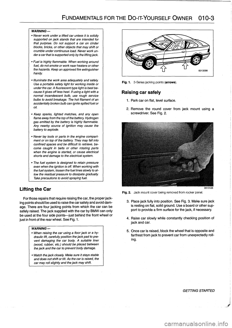
Lifting
the
Car
FUNDAMENTALS
FOR
THE
DO-ITYOURSELF
OWNER
010-
3
For
those
repairs
that
require
raising
the
car,
theproper
jack-
ing
points
should
beused
to
raise
thecar
safely
and
avoid
dam-
age
.
There
are
four
jacking
points
from
which
thecar
can
be
safely
raised
.
The
jacksupplied
with
thecar
by
BMW
can
only
be
used
at
the
fourside
points
just
behindthe
front
wheel
or
just
in
frontof
the
rear
wheel
.
See
Fig
.
1.
WARNING
-
"
When
raising
the
car
using
a
floor
jack
ora
hy-
draulic
lift,
carefully
position
the
jack
pad
topre-
vent
damaging
the
car
body
.
A
suitable
liner
(wood,
rubber,
etc
.)
should
be
placed
between
the
jack
and
the
car
to
prevent
body
damage
.
"
Watch
the
jack
closely
.
Make
sure
ft
stays
stable
and
does
not
shift
or
tilt
.
As
the
car
is
raised,
the
car
may
rol¡
slightly
and
the
jack
may
shift
.
Fig
.
1
.
3-Seriesjacking
points
(arrows)
.
Raising
car
safely
1
.
Park
car
on
flat,
leve¡
su
rface
.
2
.
Remove
the
round
cover
from
jack
mount
using
a
screwdriver
.
See
Fig
.
2
.
0013126
Fig
.
2
.
Jack
mount
cover
being
removed
from
rocker
panel
.
3
.
Place
jack
fully
into
position
.
See
Fig
.
3
.
Make
sure
jack
is
resting
on
flat,
solid
ground
.
Use
a
board
or
other
sup-
port
to
provide
a
firm
surface
for
the
jack,
if
necessary
.
4
.
Raisecar
slowly
while
constantly
checking
position
of
jack
and
car
.
5
.
Once
car
is
raised,
block
the
wheel
that
is
opposite
and
farthest
from
jackto
prevent
car
fromunexpectedly
roll-
ing
.
GET77NG
STARTER
Page 18 of 759
010-10
FUNDAMENTALS
FOR
THE
DO-IT
YOURSELF
OWNER
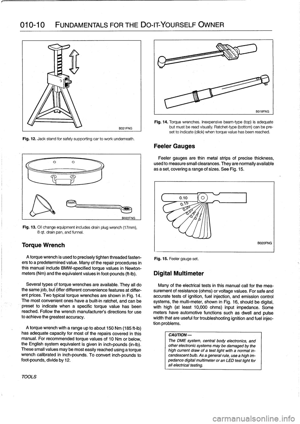
TOOLS
Torque
Wrench
B021FNG
Fig
.
12
.
Jack
stand
for
safely
supporting
car
to
work
underneath
.
B022FNG
Fig
.
13
.
Oil
change
equipment
includesdrainplug
wrench
(17mm),
8
qt
.
drain
pan,
and
funnel
.
A
torque
wrench
is
used
to
precisely
tighten
threaded
fasten-
Fig
.
15
.
Feeler
gauge
set
.
ers
to
a
predetermined
value
.
Many
of
the
repair
procedures
in
this
manual
include
BMW-specified
torquevalues
in
Newton-
meters
(Nm)
and
the
equivalent
values
in
foot-pounds
(ft-Ib)
.
Digital
Multimeter
A
torque
wrench
with
a
range
up
to
about
150
Nm
(185
ft-lb)
has
adequate
capacity
for
most
of
the
repairs
covered
in
this
manual
.
For
recommended
torque
values
of
10
Nm
or
below,the
English
system
equivalent
is
given
in
inch-pounds
(in-lb)
.
These
small
values
may
be
most
easily
reached
using
a
torque
wrench
calibrated
in
inch-pounds
.
To
convert
inch-pounds
to
foot-pounds,
divide
by12
.
Fig
.
14
.
Torque
wrenches
.
Inexpensive
beam-type
(top)
is
adequate
but
must
be
read
visually
.
Ratchet-type
(bottom)
can
be
pre-
set
to
índicate
(click)
when
torquevalue
has
been
reached
.
Feeler
Gauges
B018FNG
Feeler
gauges
are
thin
metal
strips
of
precise
thickness,
used
to
measure
small
clearances
.
They
are
normally
available
as
a
set,
covering
a
range
of
sizes
.
See
Fig
.
15
.
Several
types
of
torque
wrenches
are
available
.
They
al¡
do
Many
of
the
electrical
tests
in
Chis
manual
cal¡
for
the
mea-
the
same
job,
bu¡
óffer
different
convenience
features
at
differ-
surement
of
resistance
(ohms)
or
voltage
values
.
For
safe
and
ent
prices
.
Two
typical
torque
wrenches
are
shown
in
Fig
.
14
.
accurate
tests
of
ignition,
fuel
injection,
and
emission
control
The
most
convenient
ones
have
a
built-in
ratchet,
and
can
be
systems,
the
multi-meter,
shown
in
Fig
.
16,
should
be
digital,
preset
to
indicate
when
a
specific
torque
value
has
been
with
high
(at
least
10,000
ohms)
input
impedance
.
Some
reached
.
Followthe
wrench
manufacturer's
directions
for
use
meters
have
automotive
functions
suchas
dweil
and
pulse
to
achieve
the
greatest
accuracy
.
width
that
are
useful
fortroubleshooting
ignition
and
fuel
injec-
tion
problems
.
CAUTION-
The
DME
system,
central
body
electronics,
and
other
electronic
systems
may
be
damaged
by
the
high
current
draw
of
a
test
fight
with
a
normal
in-
candescent
bulb
.
As
a
general
rule,
usea
high
ím-
pedance
digital
multimeter
or
an
LED
test
fightforall
electrfcal
testfng
.
B020FNG
Page 21 of 759
If
steam
is
coming
from
the
engine
compartment
thenthere
is
With
the
engine
and
ignition
off,
check
for
loose
or
corroded
most
likely
a
burst
coolant
hose
or
a
large
leak
in
the
cooling
battery
cables
or
wires
at
the
battery
or
thealtemator
.
Discon-
system
.
To
find
the
leak,
look
for
signs
of
coolant
leakage
on
necting,
cleaning,
and
reinstalling
corroded
wires
and
connec-
hoses,
at
hose
connections,
or
on
the
radiator
.
Let
theengine
tors
may
solve
the
problem
.
Also
check
drive
belt
tension
as
cool
thoroughly,
then
add
coolant
or
water
to
fill
the
system
and
described
in
020
Maintenance
Program
.
start
the
engine
.
If
a
great
deal
of
water
or
coolant
flows
out
of
the
hole,
then
thecarshouldnot
be
driven
until
repairs
are
made
.
lf
there
is
slight
seepage,
then
it
may
be
possible
to
drive
TOWi
ng
a
short
distance,
adding
coolant
as
needed
.
The
cars
covered
by
this
manual
should
be
towed
witha
tow
truck
using
wheel
lift
or
flat
bed
equipment
.
Do
not
tow
thecar
on
all
four
wheels
except
for
very
short
distances
to
move
it
to
a
safe
place
.
If
thered
engine
oil
pressure
warning
light
illuminates,
imme-
diately
stop
thecar
and
turn
off
the
engine
.
Have
the
vehicle
A
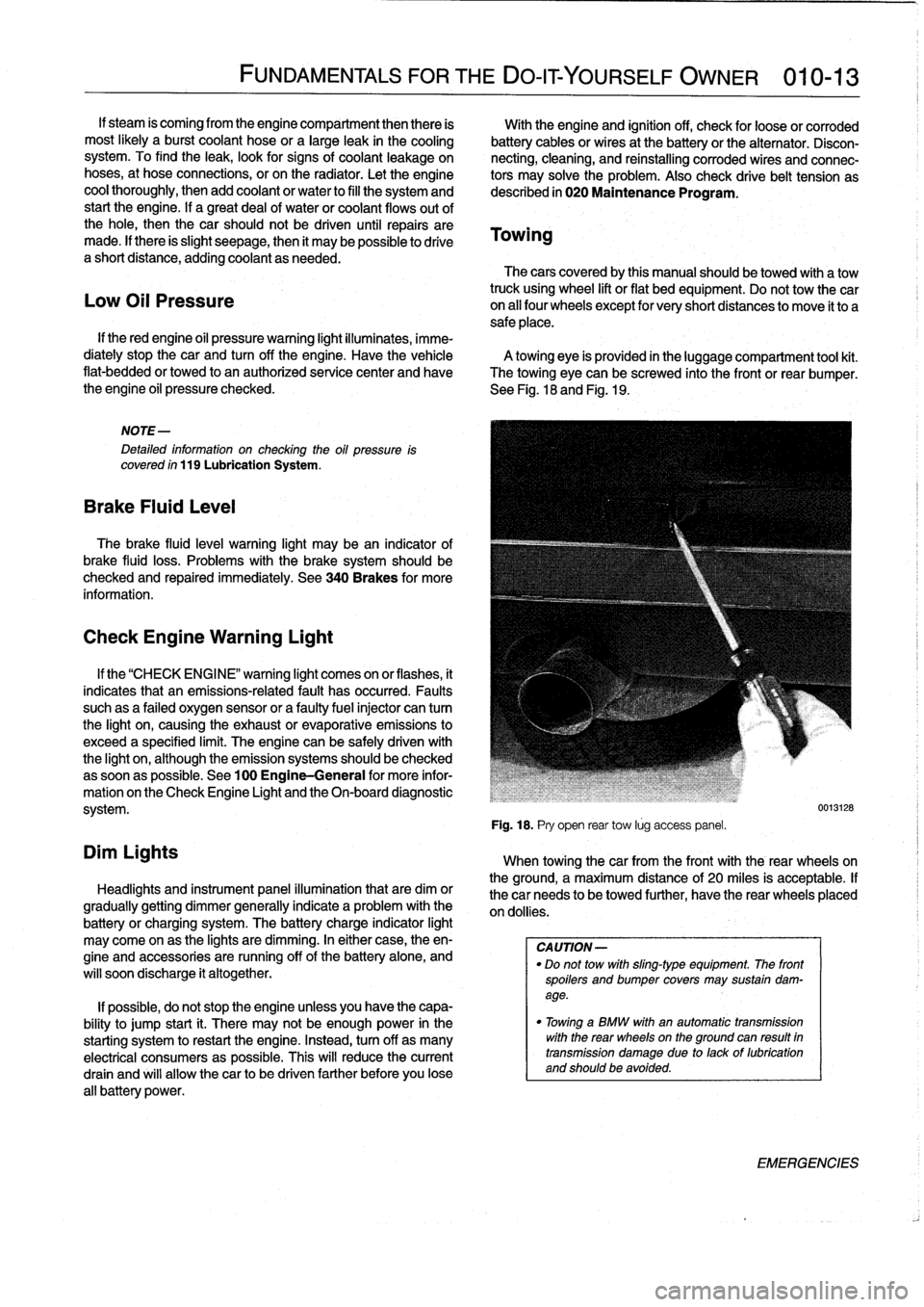
towing
eye
is
provided
in
the
luggage
compartment
tool
kit
.
flat-bedded
or
towed
to
an
authorized
service
center
and
have
The
towing
eye
can
be
screwed
into
the
front
or
rear
bumper
.
the
engine
oil
pressure
checked
.
See
Fig
.
18
and
Fig
.
19
.
Low
Oil
Pressure
NOTE-
Detafed
information
on
checking
the
oil
pressure
is
covered
ín
119
Lubrication
System
.
Brake
Fluid
Leve¡
The
brake
fluid
leve¡
warning
light
may
bean
indicator
of
brake
fluid
loss
.
Problems
with
the
brakesystem
should
be
checked
and
repaired
immediately
.
See
340Brakes
for
more
information
.
Check
Engine
Warning
Light
Dim
Lights
FUNDAMENTALS
FOR
THE
DO-IT
YOURSELF
OWNER
010-13
If
the
"CHECK
ENGI
NE"
warning
light
comes
on
or
flashes,
it
indicates
that
an
emissions-related
fault
has
occurred
.
Faults
suchas
a
failed
oxygen
sensor
or
a
faultyfuelinjector
can
tum
the
light
on,
causing
the
exhaust
or
evaporative
emissions
to
exceed
a
specified
limit
.
The
engine
can
be
safely
driven
with
the
light
on,
although
the
emission
systems
should
be
checked
assoonas
possible
.
See
100
Engine-General
for
more
infor-
mation
on
the
Check
Engine
Light
and
the
On-board
diagnostic
system
.
Headlights
and
instrument
panel
illuminationthat
are
dim
or
gradually
getting
dimmer
generally
indicate
a
problem
with
the
battery
or
charging
system
.
The
battery
charge
indicator
light
may
come
on
as
the
lights
are
dimming
.
In
either
case,
theen-
gine
and
accessories
are
running
off
of
the
battery
alone,
and
will
soon
discharge
it
altogether
.
If
possible,
do
not
stop
the
engine
unless
you
have
the
capa-
bility
to
jump
start
¡t
.
There
may
not
be
enough
power
in
the
starting
system
torestart
the
engine
.
Instead,turn
off
as
many
electrical
consumers
as
possible
.
This
will
reduce
the
current
drain
and
will
allow
thecar
to
be
driven
farther
before
you
lose
all
battery
power
.
Fig
.
18
.
Pry
open
rear
tow
lúg
access
panel
.
When
towingthecar
from
the
front
with
the
rear
wheelson
the
ground,
a
maximum
distance
of
20
miles
is
acceptable
.
If
thecar
needs
to
be
towed
further,
have
the
rear
wheels
placed
on
dollies
.
CA
UTION-
"
Do
not
tow
with
sling-type
equipment
The
front
spoilers
andbumper
covers
may
sustain
dam-
age
.
"
Towínga
BMW
with
an
automatic
transmission
with
the
rear
wheelson
the
ground
can
resuft
in
transmission
damage
due
to
lackof
lubrication
and
should
be
avoided
.
0013128
EMERGENCIES
Page 24 of 759
020-2
MAINTENANCE
PROGRAM
GENERAL
The
information
given
in
this
repair
group
includes
the
routine
checks
and
maintenance
steps
that
are
both
required
by
BMW
under
the
terms
of
the
vehicle
warranty
protection
and
recom-
mended
by
BMW
to
ensure
long
and
reliable
vehicle
operation
.
GENERAL
NOTE-
Aside
from
keeping
yourcar
in
the
bestpossible
condi-
tion,
proper
maintenance
plays
a
role
in
maintaining
full
protection
under
BMWs
new-car
warranty
coverage
.
If
in
doubtabout
the
terms
and
conditions
of
yourcark
warranty,
an
authorized
BMW
dealer
should
be
able
to
explain
them
.
NOTE-
BMW
is
constantly
updating
their
recommended
main-
tenance
procedures
and
requirements
.
The
informa-
tion
contained
here
is
as
accurate
as
possible
at
the
time
of
publication
.
If
hhere
is
any
doubt
aboutwhat
pro-
cedures
apply
to
a
specific
model
or
model
year,
or
what
intervals
should
be
followed,
remember
that
an
authorized
BMW
dealer
has
the
latest
information
on
factory-recommended
maintenance
.
BMW
Service
Indicator
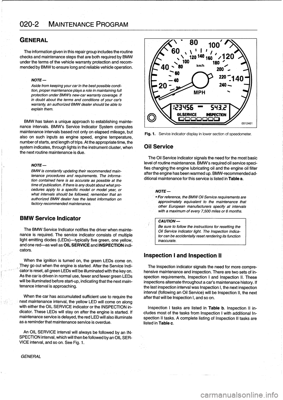
The
BMW
Service
Indicator
notifies
the
driver
when
mainte-
nance
is
required
.
The
service
indicator
consístsof
multiple
light
emitting
diodes
(lEDs)-typically
five
green,
one
yellow,
andone
red-as
well
as
OIL
SERVICE
and
INSPECTION
indi-
cators
.
When
the
ignition
is
tumed
on,the
green
LEDs
come
on
.
They
go
out
when
the
engine
is
started
.
After
the
Service
Indi-
cator
is
reset,
al¡
green
LEDs
will
be
illuminatedwith
the
keyon
.
As
thecar
is
driven
in
normal
use,
fewer
and
fewer
green
LEDs
will
be
illuminated
before
start-up,indicating
that
the
next
main-
tenance
interval
is
approaching
.
When
thecar
has
accumulated
sufficient
use
to
require
the
next
maintenance
interval,
the
yellow
LED
will
come
on
along
with
either
the
OIL
SERVICE
indicator
or
the
INSPECTION
in-
dicator
.
These
LEDs
will
stay
on
after
the
engine
is
started
.
If
maintenance
service
is
delayed,
thered
LED
will
also
illuminate
as
a
reminder
that
maintenance
service
is
overdue
.
An
OIL
SERVICE
interval
will
alwaysbe
followed
by
an
IN-
SPECTION
interval,
which
will
then
be
followed
byan
OIL
SER-VICE
interval,
andsoon
.
See
Fig
.
1
.
'
80
100/
60
II
"
1
,
ló
1
,
4
`20
140s
#
X120
100
leo
A
O
,
80
km/h`F
*101
200
,
,
~60
BMW
has
taken
a
unique
approach
to
establishing
mainte-
nance
intervals
.
BMW's
Service
Indicator
System
computes
maintenance
intervais
based
not
only
on
elapsed
mileage,
but
Fig
.
1
.
Service
indicator
display
in
lower
section
of
speedometer
.
also
on
such
inputs
as
enginespeed,engine
temperature,
number
of
starts,
and
length
oftrips
.
At
the
appropriate
time,
the
system
indicates,
through
lights
in
the
instrument
cluster,
when
Oil
Service
the
next
routine
maintenance
is
due
.
The
Oil
Service
indicator
signals
the
need
for
the
most
basic
levelof
routine
maintenance
.
BMW's
required
oil
service
speci-
fies
changing
the
engine
lubricating
oil
and
the
engine
oil
filter
after
the
engine
has
been
warmed
up
.
BMW-recommended
ad-
ditional
maintenance
for
this
service
is
listed
in
Table
a
.
NOTE-
For
reference,
the
BMW
Oil
Service
requirements
are
approximately
equivalent
to
the
maintenance
that
other
European
manufacturers
specify
at
intervals
with
a
maximum
of
every
7,500
miles
or6
months
.
CAUTION-
Be
sure
to
follow
the
ínstructions
forresetting
the
Oil
Service
indicator
fight
.
The
Inspection
indica-
tor
can
be
accidentally
reset
rendering
its
function
inaccurate
.
Inspection
l
and
Inspection
II
The
Inspection
indicator
signals
the
need
for
more
compre-
hensive
maintenance
and
Inspection
.
There
are
two
sets
of
in-
spection
requirements,
Inspection
I
and
Inspection
ll
.
These
inspections
alternate
throughout
a
car's
maintenance
history
.
If
the
last
Inspection
interval
was
Inspection
I,
the
next
Inspection
interval
(following
an
Oil
Service)
will
be
Inspection
ll,
the
next
after
that
will
be
Inspection
I,
and
so
on
.
Inspection
I
tasks
are
listed
in
Table
b
.
Inspection
II
in-
cludes
most
of
the
tasks
from
Inspection
I
with
additional
In-
spection
11
tasks
.
A
complete
listing
of
Inspection
II
tasks
are
listed
in
Table
c
.
Page 34 of 759
020-
1
2
MAINTENANCE
PROGRAM
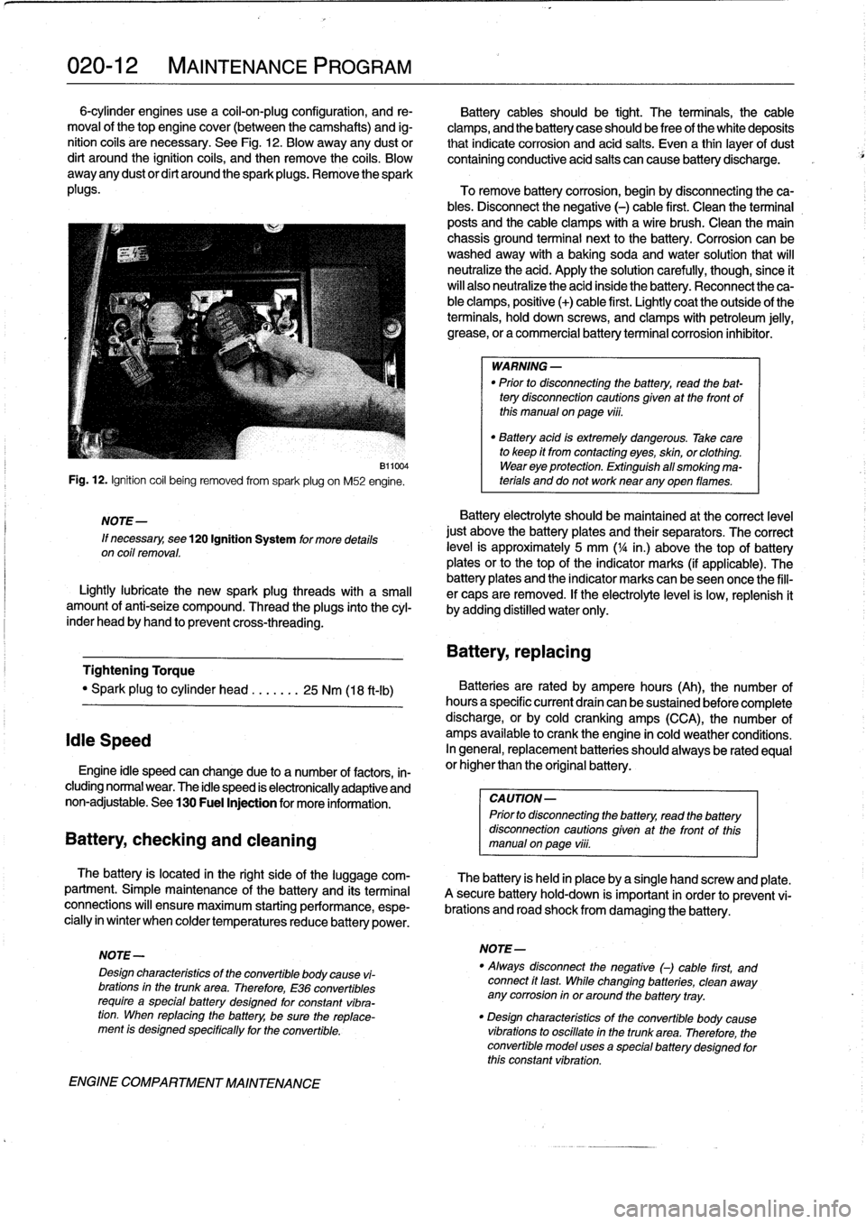
6-cylinder
engines
use
a
coil-on-plug
configuration,
and
re-
Battery
cablesshould
be
tight
.
The
terminals,
the
cable
moval
of
thetop
engine
cover
(between
the
camshafts)
and
ig-
clamps,
and
the
battery
case
should
be
freeof
the
white
deposits
nition
cofs
are
necessary
.
See
Fig
.
12
.
Blow
away
any
dust
or
that
indicate
corrosion
and
acid
salts
.
Even
a
thin
¡ayer
of
dust
dirt
around
the
ignition
coils,
and
then
remove
the
coils
.
Blow
containing
conductive
acid
salts
can
cause
battery
discharge
.
away
any
dustor
dirt
around
the
sparkplugs
.
Remove
the
spark
plugs
.
To
remove
battery
corrosion,
begin
by
disconnecting
theca-
bles
.
Disconnect
the
negative
(-)
cable
first
.
Clean
the
terminal
posts
and
the
cable
clamps
with
a
wire
brush
.
Clean
the
main
chassis
ground
terminal
next
to
the
battery
.
Corrosion
can
be
washedaway
with
a
baking
soda
and
water
solution
that
will
neutralize
the
acid
.
Apply
the
solution
carefully,
though,since
ít
will
also
neutralize
the
acid
inside
the
battery
.
Reconnect
the
ca-
ble
clamps,
positive
(+)
cable
first
.
Lightly
coat
the
outside
of
the
terminals,
hold
down
screws,
and
clamps
with
petroleum
jelly,
grease,
or
a
commercial
battery
terminal
corrosion
inhibitor
.
Fig
.
12
.
Ignition
coil
being
removed
from
spark
plug
on
M52
engine
.
NOTE-
If
necessary,
see
120
Ignition
System
for
more
details
on
coil
removal
.
B11004
Lightlylubricate
the
new
spark
plug
threads
with
a
small
amount
of
anti-seize
compound
.
Thread
the
plugs
into
the
cyl-
inder
head
byhand
to
prevent
cross-threading
.
Tightening
Torque
"
Spark
plug
to
cylinder
head
.......
25
Nm
(18
ft-ib)
Idie
Speed
Engine
¡dle
speed
canchange
due
to
a
number
of
factors,
in-
cluding
normal
wear
.
The
idle
speed
is
electronically
adaptive
and
non-adjustable
.
See
130
Fuel
Injection
for
more
information
.
Battery,
checking
and
cleaning
The
battery
is
located
in
the
right
side
of
the
luggage
com-
partment
.
Simple
maintenance
of
the
battery
and
its
terminal
connections
will
ensure
maximum
starting
performance,
espe-
cially
in
winter
when
colder
temperaturesreduce
battery
power
.
ENGINE
COMPARTMENT
MAINTENANCE
WARNING
-
"
Prior
to
disconnecting
the
battery,
read
the
bat-
tery
disconnection
cautions
given
at
the
front
of
this
manualonpage
viii
.
"
Battery
acid
is
extremely
dangerous
.
Take
care
to
keep
it
from
contacting
eyes,
skin,
or
clothing
.
Wear
eye
protection
.
Extinguish
all
smoking
ma-
terials
and
do
not
worknear
any
oyen
flames
.
Battery
electrolyte
should
be
maintained
at
the
correct
level
just
above
the
battery
plates
and
their
separators
.
The
correct
leve¡
is
approximately
5
mm
(
1
/4
in
.)
above
thetop
of
battery
plates
orto
thetop
of
the
indicator
marks
(if
applicable)
.
The
battery
plates
and
the
indicator
marks
can
beseen
once
the
fill-
er
caps
are
removed
.
If
the
electrolyte
level
is
low,
replenish
it
by
adding
distilled
water
only
.
Battery,
repiacing
Batteries
are
rated
by
ampere
hours
(Ah),
the
number
of
hoursa
specific
current
draín
can
be
sustained
before
complete
discharge,
or
by
cold
cranking
amps
(CCA),
the
number
of
amps
available
to
crank
the
engine
in
cold
weather
conditions
.
In
general,
replacement
batteries
should
alwaysbe
rated
equal
or
higherthan
the
original
battery
.
CAUTION-
Prior
to
disconnecting
the
battery,
read
the
battery
disconnection
cautions
given
at
the
front
of
thls
manual
on
page
viii
.
The
battery
is
held
in
place
bya
single
hand
screw
and
píate
.
A
secure
battery
hold-down
is
important
in
order
to
prevent
vi-
brations
and
road
shock
from
damaging
the
battery
.
NOTE-
NOTE-
"
Always
disconnect
the
negative
()
cable
first,
and
Design
characteristics
of
the
convertible
body
cause
vi-
connect
ft
last
While
changing
batteries,
clean
away
brations
in
the
trunk
area
.
Therefore,
E36
convertibles
any
corrosion
in
or
around
the
battery
tray
.
require
a
specialbattery
designed
for
constant
vibra-
tion
.
When
repiacing
the
battery,
be
sure
the
replace-
"
Design
characteristics
of
the
convertible
body
cause
ment
is
designed
specffically
for
the
convertible
.
vibrations
to
oscillate
in
the
trunk
area
.
Therefore,
the
convertible
model
uses
a
specialbattery
designed
for
this
constant
vibration
.
Page 43 of 759
GENERAL
.
.....
.
.
.
.
.
.
.
...
.
.
.
.
.
.
.
.
.
...
100-1
Cylinder
Block
and
Crankshaft
.
.
.
.
.
.
.
.
.
...
100-1
Connecting
Rods
and
Pistons
.
.
.
.
.
.
.
.
.
.
.
.
.
100-1
Cylinder
Head
and
Valvetrain
.
.
.
.
.
.
.
.
.
.
.
.
.
100-2
VANOS
(Variable
Valve
Timing)
.
.
.
.
.
.
.
.
...
100-2
DISA
(Dual
Resonance
Intake
System)
.
.
.
.
.
100-3
Engine
Management
System
.
.
.
.
.
.
.
.
.
.
.
.
.
100-3
Ignition
......
.
.
.
.........
.
.
.
.
.
.
.
.
.
.
.
.
100-5
Fuel
Delivery
..
.
.
.
.....
.
...
.
.
.
.
.
.
.
.
.
.
.
.
100-5
Cooling
System
.
...........
.
.
.
.
.
.....
.
.
100-5
Lubrication
System
.........
.
.
.
.
.
.
.
.
.
.
.
.
100-5
MECHANICALTROUBLESHOOTING
.
.
.
.
100-5
Warnings
and
Cautions
..
.
...
.
.
.
.
.
.
.
.
.
.
.
.
100-5
Cylinder
compression,
checking
.
.
.
.
.
.
.
.
.
.
.
100-6
EngineMechanical
Troubleshooting
Table
.
.
.
100-7
DRIVEABILITY
TROUBLESHOOTING
...
100-8
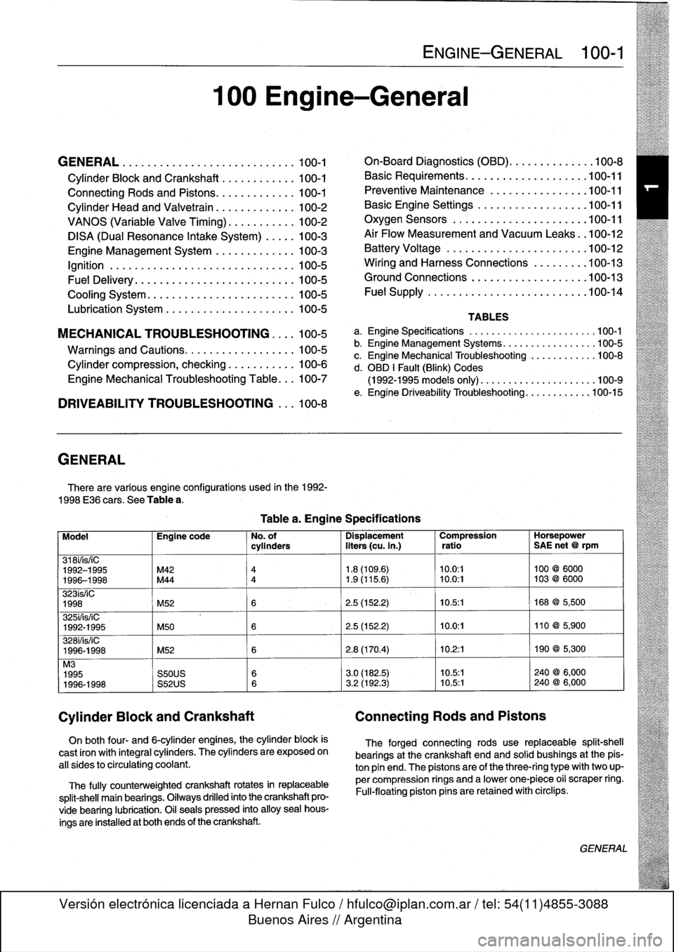
GENERAL
There
are
various
engíne
configurations
used
in
the
1992-
1998
E36
cars
.
See
Table
a
.
On
both
four-
and
6-cylinder
engines,
the
cylinder
block
is
cast
¡ron
with
integral
cyiinders
.
The
cyiinders
are
exposed
on
all
sides
to
circulating
coolant
.
The
fully
counterweighted
crankshaft
rotates
in
replaceable
split-shell
main
bearings
.
Oiiways
drilled
into
the
crankshaft
pro-
vide
bearing
lubrication
.
O¡I
seals
pressed
into
alloy
sea¡
hous-
ings
are
installedat
both
ends
of
the
crankshaft
.
100
Engine-General
Tablea
.
Engine
Specifications
ENGINE-GENERAL
100-1
On-Board
Diagnostics
(OBD)
...
.
.
.
.
.
.
.
.
.
.
.
100-8
Basic
Requirements
....
.
.
.
...
.
.
.
.
.
....
.100-11
Preventive
Maintenance
......
.
.
.
.
.
.....
100-11
Basic
Engine
Settings
..
.
.....
.
.
.
.
.
.....
100-11
Oxygen
Sensors
.
.
.
...
.
.
.
...
.
.
.
.
.
....
.100-11
Air
Flow
Measurement
and
Vacuum
Leaks
.
.100-12
Battery
Voltage
.
.
...........
.
.
.
.
.
.....
100-12
Wiring
and
Harness
Connections
.
.
.
.
.....
100-13
Ground
Connections
...
.
.....
.
.
.
.
.
.....
100-13
Fue¡
Supply
....
.
...........
.
.
..
.....
.100-14
TABLES
a
.
Engine
Specifications
...
...
...........
.
..
..
.100-1
b
.
Engine
Management
Systems
..
..
...........
..
100-5
c
.
Engine
Mechanical
Troubleshooting
..........
.
.
100-8
d
.
OBD
1
Fault
(Blink)
Codes
(1992-1995
models
only)
.
...
..
..
..........
..
.100-9
e
.
Engine
Driveability
Troubleshooting
...........
.100-15
Model
Engine
code
No
.
of
Dispiacement
Compression
Horsepower
cyiinders
liters
(cu
.
in
.)
ratio
SAE
net
@
rpm
318i/is/¡C
1992-1995
M42
4
1
.8
(109
.6)
10
.0
:1
100
@
6000
1996-1998
M44
4
1
.9
(115
.6)
~
10
.0
:1
103
@
6000
323ís/iC
1998
M52
6
2
.5
(152
.2)
10
.5
:1
168
@
5,500
325i/is/iC
1992-1995
M50
6
2
.5
(152
.2)
10
.0
:1
110
@
5,900
328i/is/iC
1996-1998
M52
6
2
.8
(170
.4)
10
.2
:1
190
@
5,300
M3
1995
S50US
6
3
.0
(182
.5)
10
.5:1
240
@
6,000
1996-1998
S52US
6
3
.2
(192
.3)
10
.5:1
240
@
6,000
Cylinder
Block
and
Crankshaft
Connecting
Rods
and
Pistons
The
forged
connecting
rods
use
replaceable
split-shell
bearings
at
the
crankshaft
endand
solid
bushings
at
the
pis-
ton
pin
end
.
The
pistonsare
of
the
three-ring
typewith
two
up-
per
compression
rings
and
a
lowerone-piece
o¡i
scraper
ring
.
Fui¡-floating
piston
pins
are
retained
with
circlips
.
GENERAL
Page 45 of 759
camshaft
secondary
drive,
causing
thecamshaft
to
"advance"
12
.5°
.
The
helical
gears
are
cut
so
that
forward
motion
of
the
gear
cup
is
transiated
into
rotational
motion
of
the
camshaft
.
See
117
Camshaft
Timing
Chain
for
testing
and
repair
infor-
mation
on
the
VANOS
system
.
DISA
(Dual
Resonance
Intake
System)
DISA,usedon
4-cylinder
engines,
is
a
dual
intake
runner
system
that
effectively
provides
the
advantages
of
both
short
and
long
intake
runners
within
the
same
engine
.
For
best
per-
formance,
long
intake
runners
aremost
beneficial
atlow-
and
mid-engine
speeds
(below
4,200
rpm),
and
short
intake
run-
ners
enhance
torque
at
high
engine
speeds
(above4,200
rpm)
.
NOTE-
The
term
DISA
comes
from
the
German
words
Differ-
enzierte
Sauganlage,
and
can
roughty
be
transiated
as
a
differing
intake
manifold
configuration
.
The
DISA
solenoid
valve
is
controlled
by
the
DME
control
module,
using
engine
speed
as
the
primary
input
.
The
main
components
of
the
system
are
the
modified
twin-section
in-
takemanifoldwith
change-over
valve,
the
twin-barrel
throttle
body,
and
the
electrical/pneumatic
actuating
components
.
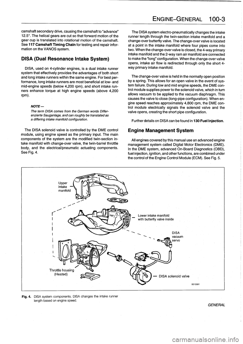
See
Fig
.
4
.
r
I
I
I
?
,
in
UpPer,
take
-1
manifold
1
-1
Throttle
housing
(Heated)
q
:lZU
Fig
.
4
.
DISA
system
components
.
DISA
changes
the
intake
runner
length
based
on
engine
speed
.
The
DISA
system
electro-pneumatically
changes
the
intake
runner
length
through
the
twin-section
intake
manifold
and
a
change-over
butterfly
valve
.
The
change-over
valve
is
located
at
a
point
in
the
intake
manifold
where
four
pipes
come
into
two
.
When
the
change-over
valve
is
closed,
the
4-way
primary
intake
manifold
and
the
2-way
ram
air
manifold
areconnected
to
make
the
"long"
configuration
.
When
the
change-overvalve
opens,
intake
air
flow
is
redirected
through
only
the
short
4-
way
primary
intake
manifold
.
The
change-over
valve
is
held
in
the
normally
open
position
bya
spring
.
Thisallows
for
an
open
valve
in
the
event
of
sys-
tem
failure
.
During
low
andmid
enginespeeds,
the
DME
con-
trol
module
supplies
power
to
the
solenoid
valve,
which
in
turn
allows
vacuum
to
be
applied
lo
the
vacuum
diaphragm
.
This
causes
the
valve
to
close
(long-pipe
configuration)
.
When
en-
gine
speed
reaches
approximately
4,800
rpm,
the
DME
con-
trol
module
electrically
signals
the
solenoid
valve
and
the
valve
opens,
creating
the
short
pipe
configuration
:
Further
detafs
on
DISA
canbefound
in
130
Fuel
Injection
.
Engine
Management
System
Al¡
enginescoveredby
this
manual
usean
advanced
engine
management
system
called
Digital
Motor
Electronics
(DME)
.
In
the
DME
system,
advancedOn-Board
Diagnostics
(OBD),
fuel
injection,
ignition,
and
otherfunctions,
are
combined
under
the
control
of
theEngine
Control
Module
(ECM)
.
See
Fig
.
5
.
-
Lower
intake
manifold
DISAvacuum
'
~servo
EíY1z
ENGINE-GENERAL
100-
3
le
-
DISA
solenoid
valve
0012591
/
with
butterfly
va¡
GENERAL