odometer BMW 318i 1998 E36 Workshop Manual
[x] Cancel search | Manufacturer: BMW, Model Year: 1998, Model line: 318i, Model: BMW 318i 1998 E36Pages: 759
Page 437 of 759

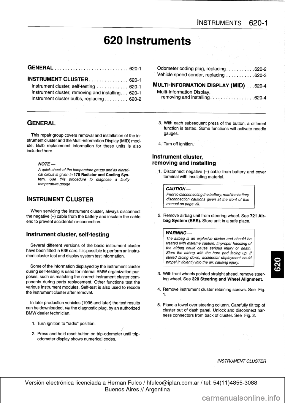
INSTRUMENT
CLUSTER
....
.
.
.
.
.
...
.
..
620-1
Instrument
cluster,
seif-testing
.
.
.......
.
..
620-1
Instrument
cluster,
removing
and
installing
...
620-1
Instrument
cluster
bulbs,
replacing
.
.
.
.
.
.
...
620-2
GENERAL
This
repair
group
covers
removal
and
installation
of
the
in-
strument
cluster
and
the
Multi-information
Display
(MID)
mod-
ule
.
Bulb
replacement
information
for
these
units
is
also
included
here
.
NOTE
-
A
quick
check
of
the
temperature
gauge
and
its
electri-
cal
circuitis
given
in
170
Radiator
and
Cooling
Sys-
tem
.
Use
this
procedure
to
diagnosea
faulty
temperature
gauge
INSTRUMENT
CLUSTER
When
servicing
the
instrument
cluster,
always
disconnect
the
negative
(-)
cable
from
the
battery
and
insulate
the
cable
end
to
prevent
accidental
re-connection
.
Instrument
cluster,
seif-testing
Severa¡
different
versions
of
the
basic
instrument
cluster
havebeen
fitted
in
E36
cars
.
It
is
possibleto
perform
an
instru-
ment
cluster
test
and
display
system
test
information
.
Some
of
the
information
displayed
by
the
instrument
cluster
during
seif-testing
is
used
for
interna¡
BMW
organizationpur-
poses,
suchasmatching
the
correct
instrument
cluster
com-
ponents
during
parts
replacement
.
Other
functions
test
the
various
instrument
modules
.
Self-test
is
also
used
to
recode
the
instrument
cluster
after
removal
.
In
later
production
vehicles
(1996
and
later)
the
test
results
canbe
downioaded,
via
the
diagnostic
plug,
byan
authorized
BMW
dealertechnician
.
1
.
Turn
ignition
to
"radio"position
.
2
.
Press
and
hold
reset
button
on
trip-odometer
untiltrip-
odometer
display
shows
numerical
codes
.
620
Instruments
4
.
Turn
off
ignition
.
Instrument
cluster,
removing
and
installing
INSTRUMENTS
620-1
GENERAL
.....
.
.
.
.
.
.
.
.
.
.........
.
....
620-1
Odometer
coding
plug,
replacing
.....
.
.
.
.
.
.
620-2
Vehicle
speed
sender,
replacing
...
.
.
.
.
.
.
.
.
620-3
MULTI-INFORMATION
DISPLAY
(MID)
.
.
.
620-4
Multi-Information
Display,
removing
and
installing
..
.
....
.
.........
620-4
3
.
With
each
subsequent
press
of
the
button,
a
different
function
is
tested
.
Some
functions
will
activate
need1e
gauges
.
1
.
Disconnect
negative
(-)
cable
from
battery
and
cover
terminal
with
insulating
material
.
CAUTION-
Prior
to
disconnectiog
the
battery,
read
the
battery
disconnection
cautionsgiven
at
the
front
of
this
manual
on
page
vi¡¡
.
2
.
Remove
airbag
unit
from
steering
wheel
.
See
721
Air-
bag
System
(SRS)
.
Store
unit
in
a
safe
place
.
WARNING
-
The
airbag
is
an
explosive
devfce
and
should
be
treated
with
extreme
caution
.
Improper
handling
of
the
airbag
could
cause
serious
injury
or
death
.
Store
the
airbag
with
the
horn
pad
facing
up
.
If
stored
facing
down,
accidental
deployment
couldpropel
it
vfolently
into
the
air,
causing
injury
.
3
.
With
front
wheels
pointed
straight
ahead,
remove
steer-
ing
wheel
.
See
320
Steering
and
Wheel
Alignment
.
4
.
Remove
instrument
cluster
retaining
screws
.
See
Fig
.
1
.
5
.
Place
a
towel
over
steering
column
.
Carefully
tilt
top
of
cluster
out
of
dash
panel
.
Unlock
and
disconnect
har-
ness
connectors
from
back
of
cluster
.
See
Fig
.
2
.
INSTRUMENT
CLUSTER
Page 438 of 759

620-2
INSTRUMENTS
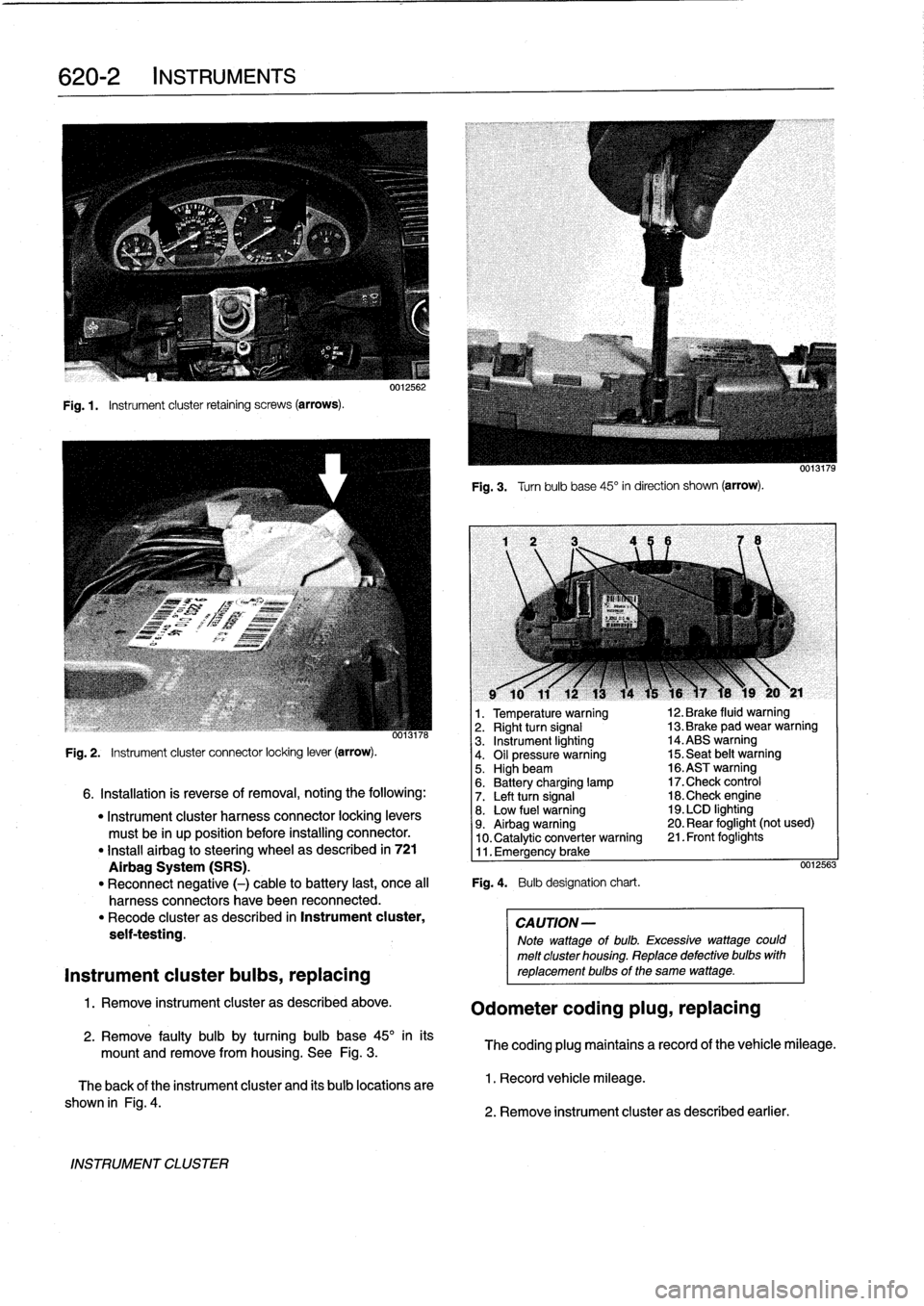
Fig
.1.
Instrument
cluster
retaining
screws
(arrows)
.
INSTRUMENT
CLUSTER
0012562
Fig
.
3
.
Turnbulb
base
45°
in
direction
shown
(arrow)
.
l
v
w
r
v
9
10
11
12
13
14
15
16
)7
18
19
20
y
21
1
.
Temperature
warning
12
.
Brake
fluid
warning
oo13n6
2
.
Right
turn
signal
13
.
Brake
pad
wear
warning
3
.
Instrument
lighting
14
.ABS
warning
Fig
.
2
.
Instrument
cluster
connector
locking
lever
(arrow)
.
4
.
Oil
pressure
warning
15
.
Seat
belt
warning5
.
Highbeam
16
.ASTwarning
6
.
Battery
charging
lamp
17
.Check
control
6
.
Installation
is
reverse
of
removal,
noting
the
following
:
7
.
Left
turn
signal
18
.Check
engine
"
Instrument
cluster
harness
connector
locking
levers
8
.
Low
fuel
warning
19
.
LCD
lighting
must
be
in
up
position
before
installing
connector
.
9
.
Airbag
warning
20
.
Rear
foglight
(not
used)
10
.
Catalytic
converter
warning
21
.
Front
foglights
"
Install
airbag
to
steering
wheel
as
described
in
721
11
.
Emergency
brake
Airbag
System
(SRS)
.
0012563
"
Reconnect
negative
(-)
cable
to
battery
last,
once
al¡
Fig
.
4
.
Bulb
designation
chart
.
harness
connectors
have
been
reconnected
.
"
Recode
cluster
as
described
in
Instrument
cluster,
CAUTION-
seif-testing
.
Note
wattage
of
bulb
.
Excessive
wattage
could
melt
cluster
housing
.
Replace
defective
bulbs
with
Instrument
cluster
bulbs,
replacing
reptacementbulbs
of
the
same
wattage
.
1
.
Remove
instrument
cluster
as
described
above
.
Odometer
coding
plug,
replacing
2
.
Remove
faulty
bulb
by
turning
bulb
base
45°
inits
mount
and
remove
from
housing
.
See
Fig
.
3
.
The
coding
plug
maintains
a
record
of
thevehicle
mileage
.
The
back
of
the
instrument
cluster
and
its
bulb
locations
are
1
.
Record
vehicle
mileage
.
shown
in
Fig
.
4
.
2
.
Remove
instrument
cluster
as
described
earlier
.
Page 755 of 759

6
INDEX
Ignition
system
general
information
120-1basictroubleshooting
principies
120-3camshaft
position
(CMP)
sensor
120-
6
camshaft
positíon
(CMP)
sensor,
replacing
(4-cylinder
engine)
120-6camshaft
position
(CMP)
sensor,
replacing
(6-cylinder
engines)
120-7
checking
for
spark
120-3
crankshaftposition/rpm
sensor
120-5
crankshaft
position/rpm
sensor,
testing/replacing
(front
mounted
sensor)
120-6
crankshaft
positíon/rpm
sensor,
testing
(rear
mounted
sensor)
120-6
disabling
ignition
system120-2
ignition
coil,
testing
and
replacing
(4-
cylinder
engines)
120-3
ignition
coil,
testing
and
replacing
(6-
cylinder
engines)
120-4
ignítion
firing
order
120-7
ignition
system
diagnostics
120-3
ignition
system
schematics
120-7
ignition
system
service
120-3knock
sensors,
replacing
120-7warnings
and
cautions
120-2
Inspectíon
I
and
Inspection
II
See
Maintenanceprogram
Instrumentpanel
See
interior
trim
Instruments
general
information
620-1
instrument
cluster,
removinglinstalling
620-1
instrument
cluster,
self-testing
620-1
instrument
cluster
bulbs,
replacing
620-2
multi-information
display
(MID),
620-4
multi-information
display
(MID),
removing/installing
620-4
odometer
coding
plug,
replacing
620-
2
vehicle
speed
sensor,
replacing
620-3
Intake
manifold
4-cylinder
engíne,
removing
113-3
6-cylinder
engine,
removing
113-11
See
alsoCylinder
head
removal
and
installation
Intake
air
temperaturesensor
See
Fuel
injection
Interior
trim
general
information
513-1
center
console,
removing/installing
513-1
dashboard,
removing/installing
513-3
glove
compartment,
removing/
installing
513-2
lower
left
dash
panel,
removing/
installing
513-2
J
Jump
startíng
010-12
K
Knock
sensor
See
Ignition
system
L
Leather
upholstery
See
Maíntenance
program
Leve¡
sender
See
Fuel
pump
Lubrication
system
general
information
119-1
oil
pan,
removing/installing
(4-cylinder
engines)
119-2
oil
pan,
removing/installing
(6-cylinder
engine,
1992models)119-4
oil
pan
119-2
oil
pan,
removing/installing
(6-cylinder
engine,
1993
and
later
models)
119-6
oil
pressure,
checking
119-1
oil
pressure
warningsystem,
testing
119-2
oil
pump
119-8
oil
pump,
removing/installing
(4-cylinder
engine)
119-8
oil
pump,
removing/installing
(6-cylinder
engine)
119-9
troubleshooting
119-1
M
Maíntenance
program
general
information
020-2
accelerator
and
throttle
linkage
020-13
air
filter,
replacing
020-11
automatic
transmission
fluid
020-8
automatic
transmission
service
020-18
battery,
checking
and
cleaning
020-12
battery,
replacing
020-12
BMW
service
indicator
020-2
body
and
hinges,
lubricating
020-19
brake
fluid
020-9
brake
fluid,
replacing
020-17
brake
pad/rotor
wear,
checking
020-17
brake
system,
inspecting
020-17
clutch
fluid,
checking
020-19
cooling
system
service
020-14
drive
axle
joint
boots,
inspecting
020-19
engine
coolant
(anti-freeze)
020-9
engine
drive
belts
020-13
engine
oil,
checking
leve¡
020-9
Maintenance
program
(cont
.)
engine
oil
and
filter,
changing020-9engine
oil
service
020-9
exhaust
system,
inspecting
020-18
exterior
washing020-20
final
drive
gear
oil
020-9
final
drive
oil
level,
checking
020-18
front
suspension
and
steering
linkages,
inspecting
020-18
fuel
filter,
replacing
020-16
fuel
tank
and
fuel
lines,
inspecting
020-19
¡dle
speed
020-12
inspection
I
and
inspection
11
020-2
interior
care020-20
leather
upholstery
and
trim
020-20
maintenance
tables
020-3
manual
transmission
fluid,
checking
and
filling
020-18manual
transmission
fluid
020-8
manual
transmission
service
020-18oxygensensors
020-15
parking
brake,
checking
020-17
polishing
020-20
poly-ribbed
belt,
replacing
020-13
power
steering
fluid
020-9
power
steering
fluid,
checking
leve¡
020-14
rear
suspension,
inspecting
020-18
resetting
service
indicator
020-3
seat
belts
020-20
spark
plugs,
replacing
020-11
special
cleaning
020-20
tires,
checking
inflation
pressure
020-17
tires,
rotating
020-17
v-belt,
replacing
020-13
washing
chassis
020-20waxing020-20
windshield
wiperblade
maintenance
020-19
wheels,
aligníng
020-17
Manual
transmission
See
also
Maintenance
program
See
also
Transmission-general
general
information
230-1
back-up
light
switch,
replacing
230-2
inputshaft
sea¡,
replacing
(transmission
installed)
230-5
output
shaftsea¡,
replacing
(transmission
installed)
230-4
selector
shaft
sea¡,
replacing
(transmission
installed)
230-3
transmission
fluid,
replacing
230-2
transmission
fluidlevel,
checking
230-2
transmission
fluid
service
230-1
transmission
removal
and
installation
230-5
transmission,
removing/installing
230-
6
transmission
service
230-2
Mass
air
flow
sensor
See
Fuel
Injection