window BMW 320i XDRIVE SEDAN 2014 Owners Manual
[x] Cancel search | Manufacturer: BMW, Model Year: 2014, Model line: 320i XDRIVE SEDAN, Model: BMW 320i XDRIVE SEDAN 2014Pages: 242, PDF Size: 7.25 MB
Page 12 of 242
CockpitVehicle equipment
All standard, country-specific and optional
equipment that is offered in the model series is
described in this chapter. Therefore, equip‐ment is also described that is not available in a
vehicle, e. g., because of the selected optional
equipment or country variant. This also applies
for safety-related functions and systems.
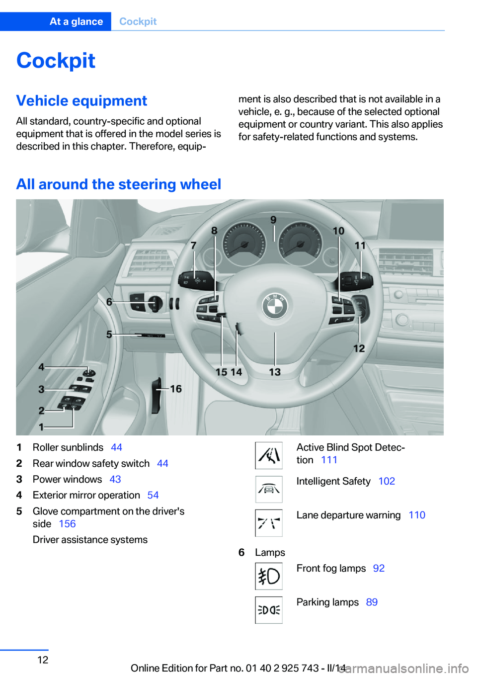
All around the steering wheel
1Roller sunblinds 442Rear window safety switch 443Power windows 434Exterior mirror operation 545Glove compartment on the driver's
side 156
Driver assistance systemsActive Blind Spot Detec‐
tion 111Intelligent Safety 102Lane departure warning 1106LampsFront fog lamps 92Parking lamps 89Seite 12At a glanceCockpit12
Online Edition for Part no. 01 40 2 925 743 - II/14
Page 26 of 242
This can unnecessarily delay the establish‐
ment of a telephone connection.
Instead, use the SOS button, refer to
page 215, in the vicinity of the interior mirror.
Environmental conditions▷Say the commands, numbers, and letters
smoothly and with normal volume, empha‐
sis, and speed.▷Always say commands in the language of
the voice activation system.▷Keep the doors, windows, and glass sun‐
roof closed to prevent noise interference.▷Avoid making other noise in the vehicle
while speaking.Seite 26At a glanceVoice activation system26
Online Edition for Part no. 01 40 2 925 743 - II/14
Page 35 of 242
can be taken with you to another vehicle
equipped with the Personal Profile function.
The following export options are available:▷BMW Online.▷Via the USB port to a USB device.
Popular file systems for USB devices are
supported. FAT32 and exFAT are the rec‐
ommended formats for profile export.
Other formats may not support the export.1."Settings"2."Profiles"3."Export profile"4.BMW Online: "BMW Online"
USB interface: "USB device"
Importing profiles
Existing settings and contacts are overwritten
with the imported profile.
1."Settings"2."Profiles"3."Import profile"4.BMW Online: "BMW Online"
USB interface: "USB device"
Using the guest profile
The guest profile can be used to make individ‐
ual settings that are saved in none of the three
personal profiles.
This can be useful for drivers who are using
the vehicle temporarily and do not have their
own profile.
1."Settings"2."Profiles"3.Open "Guest".
The guest profile cannot be renamed. It is not
assigned to the current remote control.
Display profile list during start
The profile list can be displayed during each
start for selecting the desired profile.1."Settings"2."Profiles"3.Open "Options".4."Display user list at startup"
Using the remote control
Note Take the remote control with youPeople or animals left unattended in a
parked vehicle can lock the doors from the in‐
side. Always take the remote control with you
when leaving the vehicle so that the vehicle
can then be opened from the outside.◀
Unlocking Press the button on the remote con‐
trol.
The vehicle is unlocked.
Welcome lamps, interior lamp and courtesy
lamps are switched on.
You can set how the vehicle is to be unlocked.
Performing settings, refer to page 41.
The alarm system, refer to page 41, is dis‐
armed.
Convenient opening
The remote control can be used to open the
windows and the glass sunroof after unlocking.
Press and hold the button on the re‐
mote control.
Releasing the button stops the motion.
Locking Press the button on the remote control.
Seite 35Opening and closingControls35
Online Edition for Part no. 01 40 2 925 743 - II/14
Page 39 of 242
The trunk lid unlocks.Comfort Access
The concept The vehicle can be accessed without activat‐
ing the remote control.
All you need to do is to have the remote con‐ trol with you, such as in your pants pocket.
The vehicle automatically detects the remote
control when it is nearby or in the passenger
compartment.
Comfort Access supports the following func‐
tions:▷Unlocking/locking of the vehicle.▷Convenient closing.▷Open the trunk lid individually.▷Open trunk lid with no-touch activation▷Start the engine.
Functional requirements
▷There are no external sources of interfer‐
ence nearby.▷To lock the vehicle, the remote control
must be located outside of the vehicle.▷The next unlocking and locking cycle is not
possible until after approx. 2 seconds.▷The engine can only be started if the re‐
mote control is in the vehicle.
Comparison with ordinary remote
control
The functions can be controlled by pressing the buttons of the remote control or Comfort
Access.
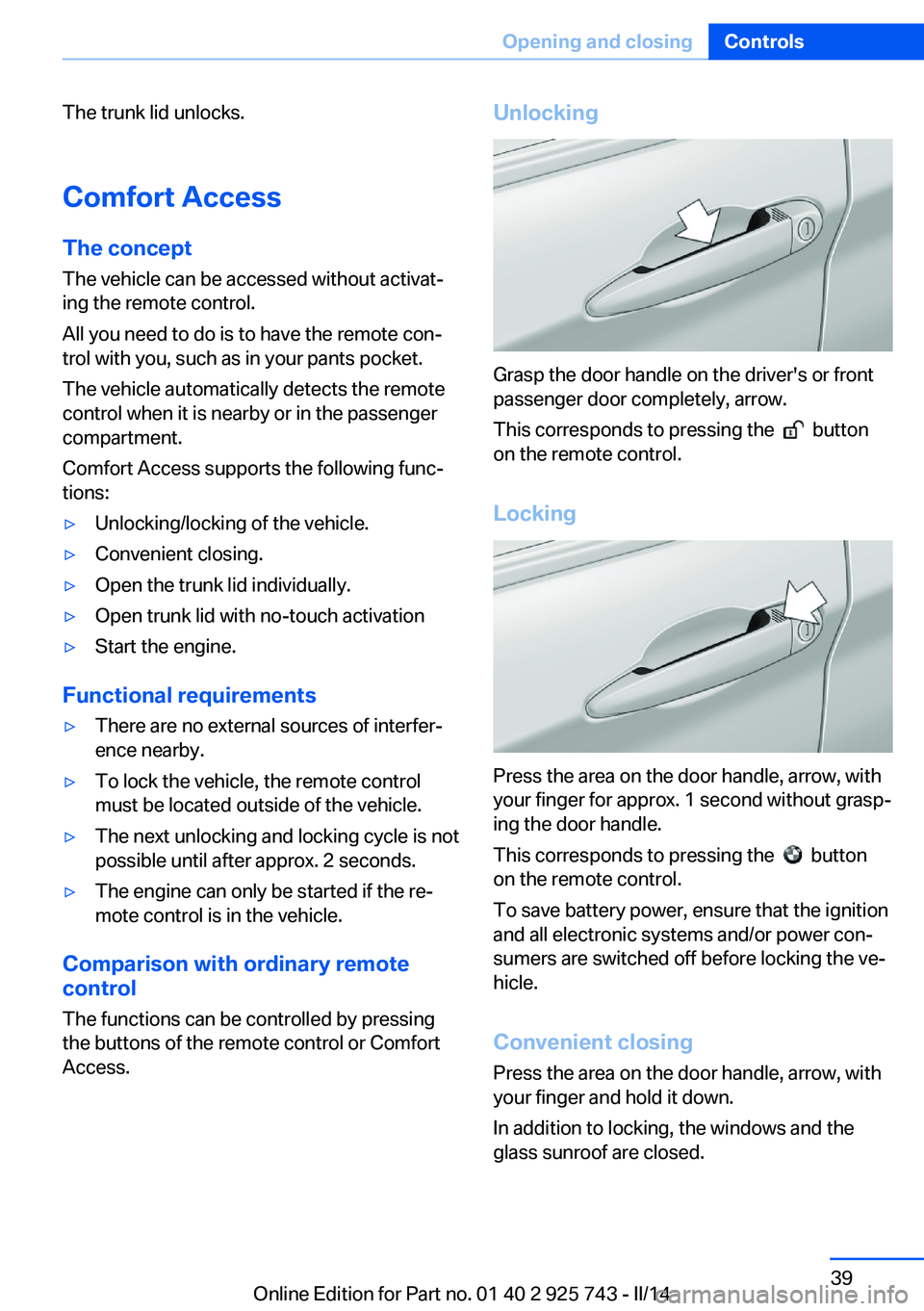
Unlocking
Grasp the door handle on the driver's or front
passenger door completely, arrow.
This corresponds to pressing the
button
on the remote control.
Locking
Press the area on the door handle, arrow, with
your finger for approx. 1 second without grasp‐
ing the door handle.
This corresponds to pressing the
button
on the remote control.
To save battery power, ensure that the ignition
and all electronic systems and/or power con‐
sumers are switched off before locking the ve‐
hicle.
Convenient closing Press the area on the door handle, arrow, with
your finger and hold it down.
In addition to locking, the windows and the
glass sunroof are closed.
Seite 39Opening and closingControls39
Online Edition for Part no. 01 40 2 925 743 - II/14
Page 43 of 242
Interior motion sensorThe windows and glass sunroof must be
closed for the system to function properly.
Avoiding unintentional alarms
The tilt alarm sensor and interior motion sen‐
sor can be switched off together, such as in
the following situations:▷In automatic car washes.▷In duplex garages.▷During transport on car-carrying trains, at
sea or on a trailer.▷When animals are to remain in the vehicle.
Switching off the tilt alarm sensor and
interior motion sensor
Press the remote control button again
within 10 seconds as soon as the vehicle
is locked.
The indicator lamp lights up for approx. 2 sec‐
onds and then continues to flash.
The tilt alarm sensor and interior motion sen‐
sor are switched off until the vehicle is locked
again.
Power windows
General information Take the remote control with you
Take the remote control with you when
leaving the vehicle so that children, for exam‐
ple, cannot operate the power windows and in‐
jure themselves.◀
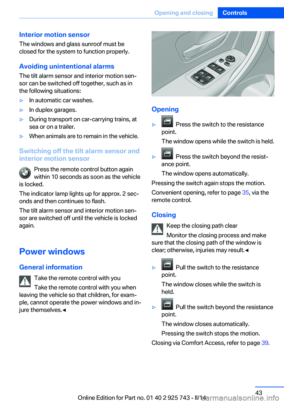
Opening
▷ Press the switch to the resistance
point.
The window opens while the switch is held.▷ Press the switch beyond the resist‐
ance point.
The window opens automatically.
Pressing the switch again stops the motion.
Convenient opening, refer to page 35, via the
remote control.
Closing Keep the closing path clear
Monitor the closing process and make
sure that the closing path of the window is
clear; otherwise, injuries may result.◀
▷ Pull the switch to the resistance
point.
The window closes while the switch is
held.▷ Pull the switch beyond the resistance
point.
The window closes automatically.
Pressing the switch stops the motion.
Closing via Comfort Access, refer to page 39.
Seite 43Opening and closingControls43
Online Edition for Part no. 01 40 2 925 743 - II/14
Page 44 of 242
Pinch protection systemIf the closing force exceeds a specific value as
a window closes, the closing action is inter‐
rupted.
The window reopens slightly.
Danger of pinching even with pinch pro‐
tection
Even with the pinch protection system, check
that the window's closing path is clear; other‐
wise, the closing action may not stop in certain
situations, e.g., if thin objects are present.◀
No window accessories
Do not install any accessories in the
range of movement of the windows; otherwise,
the pinch protection system will be impaired.◀
Closing without the pinch protection
system
Keep the closing path clear
Monitor the closing process and make
sure that the closing path of the window is clear; otherwise, injuries may result.◀
For example, if there is an external danger or if
ice on the windows prevents a window from
closing normally, proceed as follows:1.Pull the switch past the resistance point
and hold it there.
The pinch protection is limited and the
window reopens slightly if the closing force
exceeds a certain value.2.Pull the switch past the resistance point
again within approx. 4 seconds and hold it
there.
The window closes without pinch protec‐
tion.
Safety switch
The safety switch in the driver's door can be
used to prevent children, for example, from
opening and closing the rear windows using
the switches in the rear.
Switching on and off
Press the button.
The LED lights up if the safety func‐
tion is switched on.
Safety switch for rear operation
Press the safety switch when transport‐
ing children in the rear; otherwise, injury may
result if the windows are closed without super‐
vision.◀
Roller sunblinds
Roller sunblind for rear window
General information
If you are no longer able to move the roller sun‐
blind for the rear window after having activated
it a number of times in a row, the system is
blocked for a limited time to prevent overheat‐
ing. Let the system cool.
The roller sunblind for the rear window cannot
be moved at low interior temperatures.
Extending or retracting roller blind for rear window
Press the button.
Roller sunblinds for the rear side
windows
Pull out the roller sunblind at the loop and hook
it onto the bracket.
Do not open the window while the roller
sunblind is raised.
Do not open the window while the roller sun‐
blind is raised; otherwise, there is a risk of
damage at high speeds that may result in per‐
sonal injury.◀Seite 44ControlsOpening and closing44
Online Edition for Part no. 01 40 2 925 743 - II/14
Page 60 of 242
NoteMounting eyes
Only use the mounting eyes for the up‐
per retaining strap to secure child restraint fix‐
ing systems; otherwise, the mounting eyes
could be damaged.◀
Retaining strap guide Retaining strap
Make sure that the upper retaining strap
is not routed over the head restraints or sharp
edges and is free of twisting on its way to the
upper mounting point; otherwise, the belt can‐
not properly secure the child restraint fixing
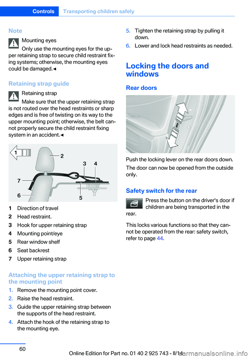
system in an accident.◀1Direction of travel2Head restraint.3Hook for upper retaining strap4Mounting point/eye5Rear window shelf6Seat backrest7Upper retaining strap
Attaching the upper retaining strap to
the mounting point
1.Remove the mounting point cover.2.Raise the head restraint.3.Guide the upper retaining strap between
the supports of the head restraint.4.Attach the hook of the retaining strap to
the mounting eye.5.Tighten the retaining strap by pulling it
down.6.Lower and lock head restraints as needed.
Locking the doors and
windows
Rear doors
Push the locking lever on the rear doors down.
The door can now be opened from the outside
only.
Safety switch for the rear Press the button on the driver's door if
children are being transported in the
rear.
This locks various functions so that they can‐
not be operated from the rear: safety switch,
refer to page 44.
Seite 60ControlsTransporting children safely60
Online Edition for Part no. 01 40 2 925 743 - II/14
Page 64 of 242
▷The external temperature is high and auto‐
matic climate control is running.▷The passenger compartment has not yet
been heated or cooled to the required
level.▷The engine is not yet at operating temper‐
ature.▷The wheels are at a sharp angle or the
steering wheel is being turned.▷After driving in reverse.▷Fogging of the windows when the auto‐
matic climate control is switched on.▷Vehicle battery is heavily discharged.▷The engine compartment lid is unlocked.▷The parking assistant is activated.▷Stop-and-go traffic.▷The selector lever is in position N or M/S.▷Use of fuel with high ethanol content.
Starting the engine
The engine starts automatically under the fol‐
lowing conditions:
▷Automatic transmission:
By releasing the brake pedal.▷Manual transmission:
The clutch pedal is pressed.
After the engine starts, accelerate as usual.
Safety mode
After the engine switches off automatically, it
will not start again automatically if any one of
the following conditions are met.
▷The driver's safety belt is unbuckled and
the driver's door is open.▷The hood was unlocked.
Some indicator lamps light up for varying
lengths of time.
The engine can only be started via the Start/
Stop button.
Note
Even if driving away was not intended, the de‐
activated engine starts up automatically in the
following situations:▷Excessive warming of the passenger com‐
partment when the cooling function is
switched on.▷The steering wheel is turned.▷Automatic transmission: change from se‐
lector lever position D to N, R or M/S.▷Automatic transmission: change from se‐
lector lever position P to N, D, R or M/S.▷The vehicle begins rolling.▷Fogging of the windows when the auto‐
matic climate control is switched on.▷Vehicle battery is heavily discharged.▷Excessive cooling of the passenger com‐
partment when the heating is switched on.▷Low brake vacuum pressure; this can oc‐
cur, for example, if the brake pedal is de‐
pressed a number of times in succession.
Activating/deactivating the system
manually
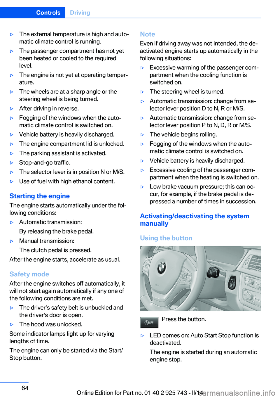
Using the button
Press the button.
▷LED comes on: Auto Start Stop function is
deactivated.
The engine is started during an automatic
engine stop.Seite 64ControlsDriving64
Online Edition for Part no. 01 40 2 925 743 - II/14
Page 69 of 242
tainer. Use BMW’s Windshield Washer Con‐
centrate or the equivalent.◀
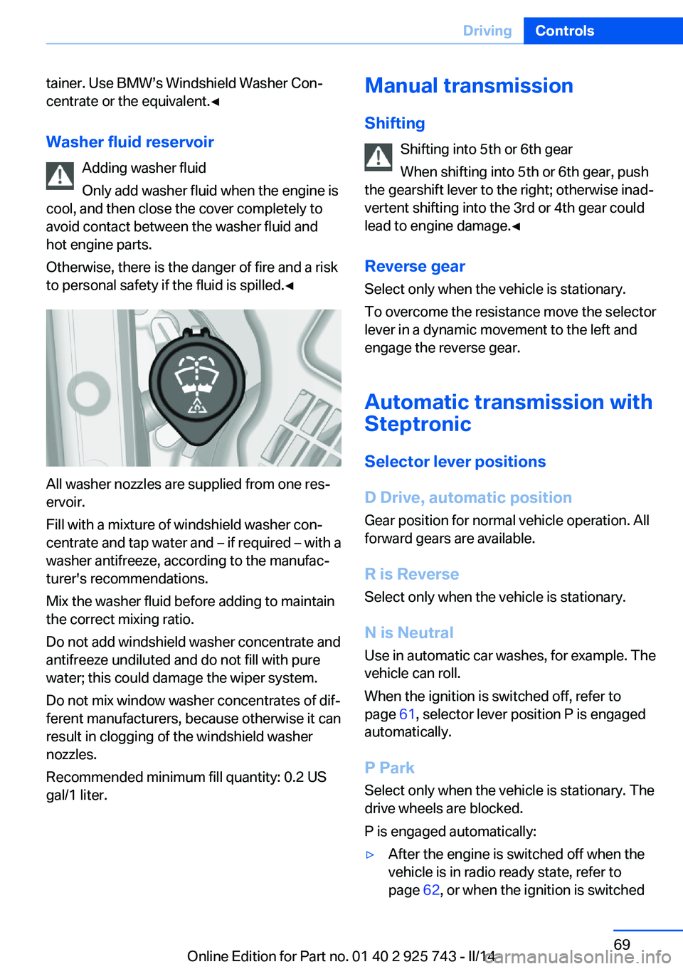
Washer fluid reservoir Adding washer fluid
Only add washer fluid when the engine is
cool, and then close the cover completely to
avoid contact between the washer fluid and
hot engine parts.
Otherwise, there is the danger of fire and a risk
to personal safety if the fluid is spilled.◀
All washer nozzles are supplied from one res‐
ervoir.
Fill with a mixture of windshield washer con‐
centrate and tap water and – if required – with a
washer antifreeze, according to the manufac‐
turer's recommendations.
Mix the washer fluid before adding to maintain
the correct mixing ratio.
Do not add windshield washer concentrate and
antifreeze undiluted and do not fill with pure
water; this could damage the wiper system.
Do not mix window washer concentrates of dif‐
ferent manufacturers, because otherwise it can
result in clogging of the windshield washer
nozzles.
Recommended minimum fill quantity: 0.2 US
gal/1 liter.
Manual transmission
Shifting Shifting into 5th or 6th gear
When shifting into 5th or 6th gear, push
the gearshift lever to the right; otherwise inad‐
vertent shifting into the 3rd or 4th gear could
lead to engine damage.◀
Reverse gear
Select only when the vehicle is stationary.
To overcome the resistance move the selector
lever in a dynamic movement to the left and
engage the reverse gear.
Automatic transmission with
Steptronic
Selector lever positions
D Drive, automatic position
Gear position for normal vehicle operation. All
forward gears are available.
R is Reverse
Select only when the vehicle is stationary.
N is Neutral Use in automatic car washes, for example. The
vehicle can roll.
When the ignition is switched off, refer to
page 61, selector lever position P is engaged
automatically.
P Park Select only when the vehicle is stationary. The
drive wheels are blocked.
P is engaged automatically:▷After the engine is switched off when the
vehicle is in radio ready state, refer to
page 62, or when the ignition is switchedSeite 69DrivingControls69
Online Edition for Part no. 01 40 2 925 743 - II/14
Page 95 of 242
Protective action
Airbags are not triggered in every impact situa‐
tion, e.g., in less severe accidents or rear-end
collisions.
Information on how to ensure the optimal
protective effect of the airbags▷Keep at a distance from the airbags.▷Always grasp the steering wheel on the
steering wheel rim, holding your hands at
the 3 o'clock and 9 o'clock positions, to
keep the danger of injury to your hands or
arms as low as possible if the airbag is trig‐
gered.▷There should be no people, animals, or ob‐
jects between an airbag and a person.▷Do not use the cover of the front airbag on
the front passenger side as a storage area.▷Keep the dashboard and window on the
front passenger side clear, i.e. do not cover
with adhesive labels or coverings, and do
not attach holders such as for navigation
instruments and mobile phones.▷Make sure that the front passenger is sit‐
ting correctly, i.e., keeps his or her feet and
legs in the footwell; otherwise, leg injuries
can occur if the front airbag is triggered.▷Do not place slip covers, seat cushions or
other objects on the front passenger seat
that are not approved specifically for seats
with integrated side airbags.▷Do not hang pieces of clothing, such as
jackets, over the backrests.▷Make sure that occupants keep their heads
away from the side airbag and do not rest
against the head airbag; otherwise, injuries
can occur if the airbags are triggered.▷Do not remove the airbag restraint system.▷Do not remove the steering wheel.▷Do not apply adhesive materials to the air‐
bag cover panels, cover them or modify
them in any way.▷Never modify either the individual compo‐
nents or the wiring in the airbag system.
This also applies to steering wheel covers,
the dashboard, the seats, the roof pillars
and the sides of the headliner.◀
Even when all instructions are followed closely,
injury from contact with the airbags cannot be
ruled out in certain situations.
The ignition and inflation noise may lead to
short-term and, in most cases, temporary
hearing impairment in sensitive individuals.
In the case of a malfunction, deactivation
and after triggering of the airbags
Do not touch the individual components imme‐
diately after the system has been triggered;
otherwise, there is the danger of burns.
Only have the airbags checked, repaired or dis‐
mantled and the airbag generator scrapped by
the service center or a workshop that has the
necessary authorization for handling explo‐
sives.
Non-professional attempts to service the sys‐
tem could lead to failure in an emergency or
undesired triggering of the airbag, either of
which could result in injury.◀
Warnings and information on the airbags are
also found on the sun visors.
Functional readiness of the airbag
system
When the ignition is switched on, the
warning lamp in the instrument cluster
lights up briefly and thereby indicates
the operational readiness of the entire airbag
system and the belt tensioner.
Airbag system malfunctioning
▷Warning lamp does not come on when the
ignition is turned on.▷The warning lamp lights up continuously.Seite 95SafetyControls95
Online Edition for Part no. 01 40 2 925 743 - II/14