Systems main relay BMW 323i 1992 E36 Workshop Manual
[x] Cancel search | Manufacturer: BMW, Model Year: 1992, Model line: 323i, Model: BMW 323i 1992 E36Pages: 759
Page 147 of 759
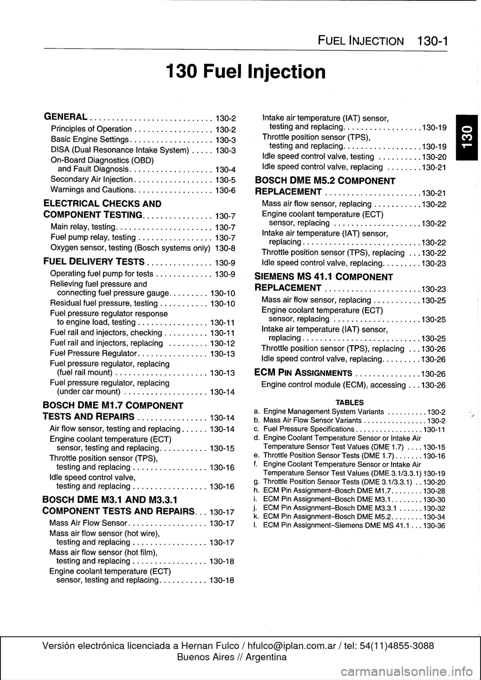
GENERAL
.
.
.
.
.
.
.
.
.
...
.
.
.
.
.
.
.
.........
130-2
Intake
air
temperature
(IAT)
sensor,
Principles
of
Operatinn
.
.
.
.
.
.
.
.
.
.........
130-2
testing
and
replacing
...
.
...
.
.
.
.......
.
130-19
Basic
Engine
Settings
.
.
.
.
.
.
.
.
.
.
.
.
.
.
...
:
.
130-3
Throttle
position
sensor
(TPS),
DISA
(Dual
Resonance
Intake
System)
.
.
.
.
.
130-3
testing
and
replacing
...
.
...
.
.
.
.
.
...
.
.
.130-19
On-Board
Diagnostics
(OBD)
Idle
speed
control
valve,
testing
.
.
.
.
.
.
.
.
.
.
130-20
and
Fault
Diagnosis
.
.
....
.
......
.
.
.
...
130-4
Idle
speed
control
valve,
replacing
.
.
.
.
.
.
..
130-21
SecondaryAir
Injection
.
.
.....
.
.........
.
130-5
BOSCH
DME
M5
.2
COMPONENT
Warnings
and
Cautions
.
.
...
.
.
.
.........
.
130-6
REPLACEMENT
.....
.
......
.
....
.
.
.
..
130-21
ELECTRICAL
CHECKSAND
Mass
air
flow
sensor,
replacing
.
.
....
.
....
130-22
COMPONENT
TESTING
.
.
.
.
.
.
.
.
...
.
.
.
.
.
130-7
Engine
coolant
temperature
(ECT)
Main
sensor,
replacing
..
.
.
.
.
.
.
.
.
.
.
.
.
.
.
.
.
.
.
130-22
rela
y
testing
130
-7
,...
.
.
.
.
.
.
.
.
.
...
.
.
.
.
.
.
.
Intake
air
temperature
(IAT)
sensor,
Fuel
pump
relay,
testing
.
.
.
.
.
.
.
...
.
.
.
.
.
.
.
130-7
rep
lacin
.
.
.
.
.
.
.
.
.
.
.g
.
.
.
.
.
.
.
...
.
.
.
..
.130-22
Oxygen
sensor,
testing
(Boschsystems
only)
130-8
Throttle
poson
sensor
(TPS)
replacing
13022
,
..
.-
FUEL
DELIVERY
TESTS
...
.
....
.
.
.
...
.
130-9
Idle
speed
control
valve,
replacing
...
.
....
.130-23
Operating
fuel
pump
for
tests
.
.
.......
.
...
130-9
SIEMENS
MS
41
.1
COMPONENT
Relieving
fuel
pressure
and
REPLACEMENT
.
...
.
.
.
.
.
.......
.
....
.130-23
connecting
fuel
pressure
gauge
......
.
..
130-10
Residual
fuel
pressure,
testing
.
.....
.
.
.
.
.
130-10
Mass
air
flow
sensor,
replacing
.
.......
.
.
.130-25
Fuel
pressure
regulator
response
Engine
coolant
temperature
(ECT)
to
engine
load,
testing
.
.
.
.
.
.
.
.
.
.
.
.
.
.
.
.
130-11
sensor,
replacing
.....
.
.
.
.
.
.........
.130-25
Fuel
rail
and
injectors,
checking
...
.
.
.
.
.
.
.
130-11
Intake
air
temperature
(IAT)
sensor,
replacing
.
.
.
.
.
.....
.
.
.
.
.
.
.
.......
.
.
.130-25
Fuel
rail
and
injectors,
replacing
..
.
.
.
.
.
.
.
130-12
Throttleposition
sensor
(TPS),
replacing
.
.
.
130-26
Fuel
PressureRegulator
.........
.
.
.
.
.
.
.
130-13
Idle
s
eed
control
valve,
re
lacin
130-26
Fuel
pressure
regulatorreplacing
p
p
g
.'''...
.
'
,
(fuel
rail
mount)
...
.
.
.
.
.
.............
130-13
ECM
PIN
ASSIGNMENTS
.............
.
.
130-26
Fuel
pressure
regulator,
replacing
Engine
control
module
(ECM),
accessing
...
130-26
(undercar
mount)
.
.
.
.
.
.
.
.
.........
.
.
130-14
BOSCH
DME
M1
.7
COMPONENT
TESTS
AND
REPAIRS
.
.
.
.
.
...
.
.
.
.
.
.
.
.
130-14
Air
flow
sensor,
testing
and
replacing
.
.
.
.
.
.
130-14
Engine
coolant
temperature
(ECT)
sensor,
testing
and
replacing
...
.
.
.
.
.
.
.
.
130-15
Throttle
position
sensor
(TPS),
testing
and
replacing
.
..........
.
.....
130-16
Idle
speed
control
valve,
testing
and
replacing
.
.
.
.
.
............
130-16
BOSCH
DME
M3
.1
AND
M33
.1
COMPONENT
TESTS
AND
REPAIRS
.
.
.
130-17
Mass
Air
Flow
Sensor
.
.
.
.
.
.
.
.
.....
.
.
.
.
.130-17
Mass
air
flow
sensor
(hotwire),testing
and
replacing
.
.
.
.
.
.....
.
.
.
.
.
.
.
130-17
Mass
air
flow
sensor
(hot
film),
testíng
and
replacing
.
.
.
.....
.
.
.
.
.
.
.
.
.
130-18
Engine
coolant
temperature
(ECT)
sensor,
testing
and
replacing
..
.
.
.
.
.
...
.
130-18
130
Fuel
i
n
jection
FUEL
INJECTION
130-1
TABLES
a
.
Engine
Management
System
Variants
.........
.130-2
b
.
Mass
Air
Flow
Sensor
Variants
..
.
..
..........
.130-2
c
.
Fuel
Pressure
Specifications
..
.
.
...
..........
130-11
d
.
Engine
Coolant
Temperature
Sensor
or
Intake
Air
Temperature
Sensor
Test
Values
(DME
1
.7)
...
.
130-15
e
.
ThrottlePosition
Sensor
Tests
(DME
1
.7)
......
.130-16
f
.
Engine
Coolant
Temperature
Sensor
or
Intake
Air
Temperature
Sensor
Test
Values
(DME
3
.1/3
.3
.1)130-19
g
.
Throttle
Position
Sensor
Tests
(DME
3
.1/3.3
.1)
.
.130-20
h
.
ECM
Pin
Assignment-Bosch
DME
M1
.7
....
.
..
.130-28
i.
ECM
Pin
Assignment-Bosch
DME
M3
.1
.......
.130-30
j
.
ECM
Pin
Assignment-Bosch
DME
M3
.3
.1
.....
.130-32
k
.
ECM
Pin
Assignment-Bosch
DME
M5
.2
.......
.
130-34
I.
ECM
Pin
Assignment-Siemens
DME
MS
41
.1
..
.
130-36
Page 153 of 759
ELECTRICAL
CHECKS
AND
COMPONENT
TESTING
Main
relay,
testing
The
main
relay
is
energized
via
the
engine
control
module
and
supplies
plus
(+)
power
to
the
many
of
the
engine
man-
agement
components
and
subsystems,
including
the
fuel
pump
relay
.
If
this
relay
is
faulty,
the
engine
will
not
start
.
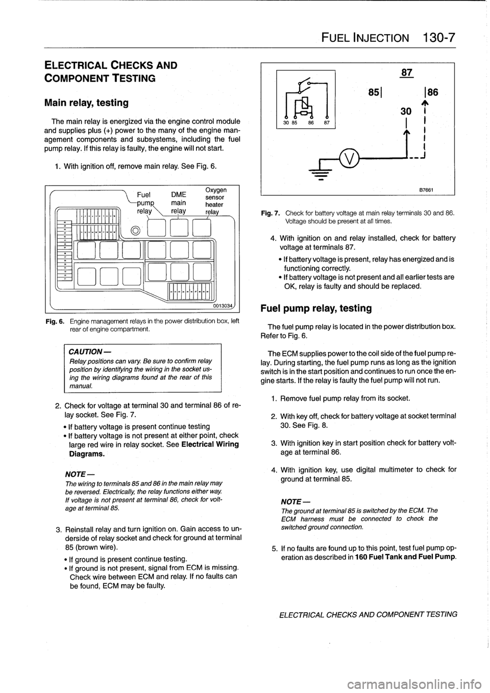
1
.
With
ignition
off,
remove
main
relay
.
See
Fig
.
6
.
.
iommooommmoi
~
"""
Fuel
DME
sensor
CA
UTION-
Relay
positions
can
vary
.
Be
sure
to
confirm
relay
position
by
identífyíng
the
wiring
in
the
socket
us-
ingthe
wiring
diagramsfound
at
the
rearof
this
manual
.
0013034)
Fuel
pump
relay,
testing
FUEL
INJECTION
130-
7
87
851186
30
~j
1
.
Remove
fuel
pump
relay
from
its
socket
.
87661
Fig
.
7
.
Check
for
battery
voltage
at
main
relay
terminals
30
and
86
.
Voltage
should
be
present
at
all
times
.
4
.
With
ignition
on
and
relay
installed,
check
for
battery
voltage
at
terminals
87
.
"
If
battery
voltage
is
present,relay
has
energized
and
is
functioningcorrectly
.
"
lf
battery
voltage
is
not
present
and
al¡
earlier
tests
are
OK,
relay
is
faulty
and
should
be
replaced
.
Fig
.
6
.
Engine
management
relays
in
the
power
distribution
box,
left
rear
of
engine
compartment
.
The
fuel
pump
relay
is
located
in
the
power
distribution
box
.
Refer
to
Fig
.
6
.
The
ECM
supplies
power
to
the
coil
side
of
the
fuel
pump
re-
lay
.
During
starting,
the
fuel
pump
runs
as
long
as
the
ignition
switch
isin
the
start
position
and
continues
to
run
once
theen-
gine
starts
.
If
the
relay
ís
faulty
the
fuel
pump
will
notrun
.
2
.
Check
for
voltage
at
terminal
30
and
terminal
86
of
re-
¡ay
socket
.
See
Fig
.
7
.
2
.
With
key
off,
check
for
batteryvoltage
at
socket
terminal
"
If
battery
voltage
is
present
continue
testing
30
.
See
Fig
.
8
.
"
lf
battery
voltage
is
not
present
at
either
point,
check
large
red
wire
in
relay
socket
.
See
Electrical
Wiring
3
.
With
ignition
key
in
start
position
check
for
battery
volt-
Diagrams
.
age
at
terminal
86
.
NOTE-
4
.
With
ignition
key,
use
digital
multimeter
to
check
for
The
wiring
to
terminals
85
and
86
in
the
main
relay
may
ground
at
terminal
85
.
be
reversed
.
Electrically,
the
relay
functions
either
way
.
lf
voltage
ís
not
present
at
terminal
86,
check
for
volt-
NOTE-
age
at
terminal
85
.
The
ground
atterminal
85
is
switched
by
the
ECM
.
The
ECM
hamess
must
be
connected
to
check
the
3
.
Reinstall
relay
and
turn
ignition
on
.
Gainaccess
to
un-
switched
ground
connection
.
derside
of
relay
socket
and
check
for
ground
at
terminal
85
(brown
wire)
.
5
.
If
no
faults
are
found
up
tothis
point,
testfuel
pump
op-
"
lf
ground
is
present
continue
testing
.
eration
as
described
in
160
Fuel
Tank
and
Fuel
Pump
.
"
If
ground
is
not
present,
signal
from
ECM
is
missing
.
Check
wire
between
ECM
and
relay
.
If
no
faults
can
be
found,
ECM
may
be
faulty
.
ELECTRICAL
CHECKS
AND
COMPONENT
TESTING
Page 163 of 759
BOSCH
DME
MM
AND
M33
.1
COMPONENT
TESTS
AND
REPAIRS
Consult
Table
a
for
engine
application
information
for
the
Bosch
DME
3
.1
and
3
.3.1
systems
.
The
DME
3
.1
and
DME
3
.3
.1
systems
are
similar
in
opera-
tion,
with
knock
control
and
VANOS
operation
being
the
key
differences
.
DME
3
.1
engines
arenot
equipped
with
VANOS
or
knock
detectors,
while
the
DM
E3
.3
.1
system
is
.
CA
UTION-
Use
onty
a
digital
multimeter
when
testing
wiring
.
Use
of
an
analog
VOM
may
damage
the
engine
control
module
.
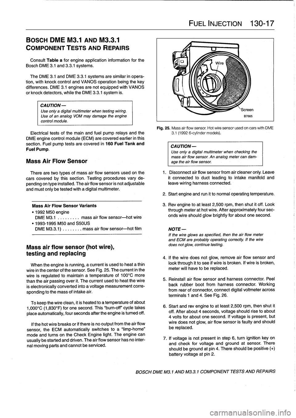
Fig
.
25
.
Mass
air
flow
sensor
.
Hot
wire
sensor
usedon
carswith
DME
Electrical
tests
of
the
main
and
fuel
pump
relays
and
the
3
.1
(1992
6-cylinder
models)
.
DME
engine
control
module
(ECM)
are
covered
earlier
in
this
section
.
Fuel
pump
tests
are
covered
in
160
Fuel
Tank
and
CAUTION-
Fuel
Pump
.
Use
only
a
digital
multimeter
when
checking
the
mass
air
flow
sensor
.
An
analog
meter
can
dam-
Mass
Air
Flow
Sensor
age
theair
flow
sensor
.
There
are
two
types
of
mass
air
flow
sensors
used
onthe
1
.
Disconnect
air
flow
sensor
from
air
cleaner
only
.
Leave
cars
covered
by
this
section
.
Testing
procedures
vary
de-
it
connected
to
duct
leading
to
intake
manifold
and
pending
on
type
installed
.
The
airflow
sensor
is
not
adjustable
leave
wiring
harness
connected
.
and
must
only
be
tested
with
a
digital
multimeter
.
Mass
Air
FlowSensor
Variants
"
1992
M50
engine
DME
M3
.1
.
.
.
.
...
..
mass
air
flow
sensor-hot
wire
"
1993-1995
M50
and
S50US
DMEM33
.1)
.
...
...
.
mass
air
flow
sensor-hot
film
Mass
air
flow
sensor
(hot
wire),
testing
and
replacing
When
the
engine
is
running,
a
current
is
used
to
heat
a
thin
wire
in
the
center
of
the
sensor
.
See
Fig
.
25
.
The
current
in
the
wire
is
regulated
to
maintain
a
temperature
of
100°C
more
than
the
air
passing
over
it
.
The
current
used
to
heat
the
wire
is
electronically
conneced
into
a
voltage
measurement
corre-
sponding
to
the
mass
of
intake
a¡
r
.
To
keep
the
wire
clean,
it
is
heated
to
a
temperature
of
about
1,000°C
(1,830°F)
for
one
second
.
This
"burn-off"
cycle
takes
place
automatically,
four
seconds
after
the
engine
is
tumed
off
.
lf
thehot
wire
breaks
or
if
there
is
no
output
from
the
air
flow
sensor,
the
ECM
automatically
switches
to
a
"limp-home"
mode
and
tucos
on
the
Check
Engine
light
.
The
engine
can
usually
be
started
and
driven
.
The
air
flow
sensor
has
no
inter-
nal
moving
parts
and
cannot
be
serviced
.
FUEL
INJECTION
130-
1
7
2
.
Start
engine
and
run
it
to
normal
operating
temperature
.
3
.
Rev
engine
toat
least
2,500
rpm,then
shut
it
off
.
Look
through
meter
at
hot
wire
.
After
approximately
four
sec-
onds
wire
should
glow
brightly
for
about
one
second
.
NOTE
-
If
the
wire
glowsas
specified,
then
the
airflow
meter
and
ECM
are
probably
operating
correctly
.
lf
the
wire
does
not
glow,
continue
testing
.
4
.
lf
the
wire
does
not
glow,
remove
air
flow
sensor
and
look
through
it
to
see
if
wire
is
broken
.
lf
wire
is
broken,
meter
will
have
to
be
replaced
.
5
.
Reinstall
air
flow
sensor
and
harness
connector
.
Peel
back
rubber
bootfrom
harness
connector
.
Working
from
rear
of
connector,
connect
digital
voltmeter
across
terminals
1
and
4
.
See
Fig
.
26
.
6
.
Start
and
rev
engine
toat
least
2,500
rpm,thenshut
it
off
.
After
about
4
seconds,
voltage
should
riseto
about
4
volts
for
about
one
second
.
lf
voltage
is
present,
but
wire
does
not
glow,
air
flow
sensor
is
faulty
and
should
be
replaced
.
7
.
lf
voltage
is
not
present
in
step
6,
turn
ignition
key
on
and
check
for
voltage
and
ground
at
sensor
.
There
should
beground
at
pin
4
.
There
should
be
positive
(+)
battery
voltage
at
pin
2
.
BOSCH
DME
M3
.1
AND
M32
.1
COMPONENT
TESTS
AND
REPAIRS
Page 254 of 759
300-6
SUSPENSION,
STEERING
AND
BRAKES-GENERAL
BATTE
RY
KL
30
ECM
MAIN
C~
RELAY
KL
15
DSC
SWITCH
LF1
;1~lZZ~
nSLn
l'
z
sJ
WHEEL
RF
c_
.
LR
r_
.
>
RR
ELECTRONIC
BRAKE
LIGHT
SWITCH
SPEED
SENSORS
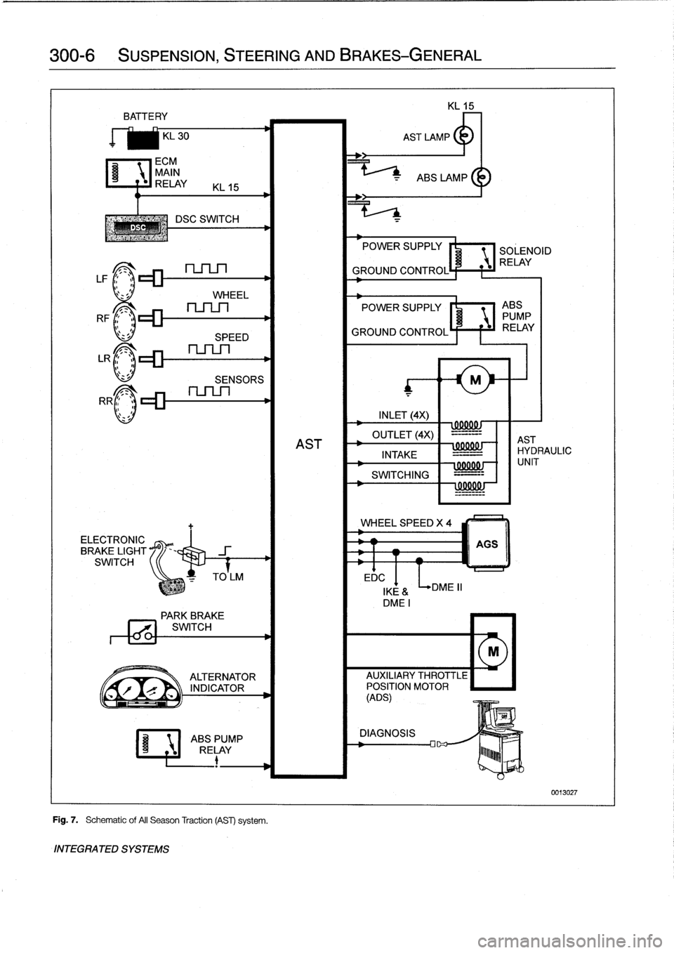
Fig
.
7
.
Schematic
of
AII
Season
Traction
(AST)
system
.
INTEGRATED
SYSTEMS
EDC
POWER
SUPPLY
SOLENOID
RELAY
GROUND
CONTROL
POWER
SUPPLY
I'
1
ABS
PUMP
GROUND
CONTROLÍ
F
f
iJ
RELAY
INLET
(4X)
wxxuw
OUTLET
(4X)
-=-=--
AST
AST
INTAKE
IHYDRAULIC
-
=-
SWITCHING
=---
!
99001
!J
WHEEL
SPEED
X
4
DME
II
000001
-
f
1
UNIT
AGS
IKE
&
DMEI
PARK
BREVE
771
SWITCH
M
ALTERNATOR
AUXILIARY
THROTTLE
r
`
INDICATOR
POSITION
MOTOR
(ADS)
ABSPUMP
DIAGNOSIS
RELAY
lu~~~b
0013027
Page 752 of 759
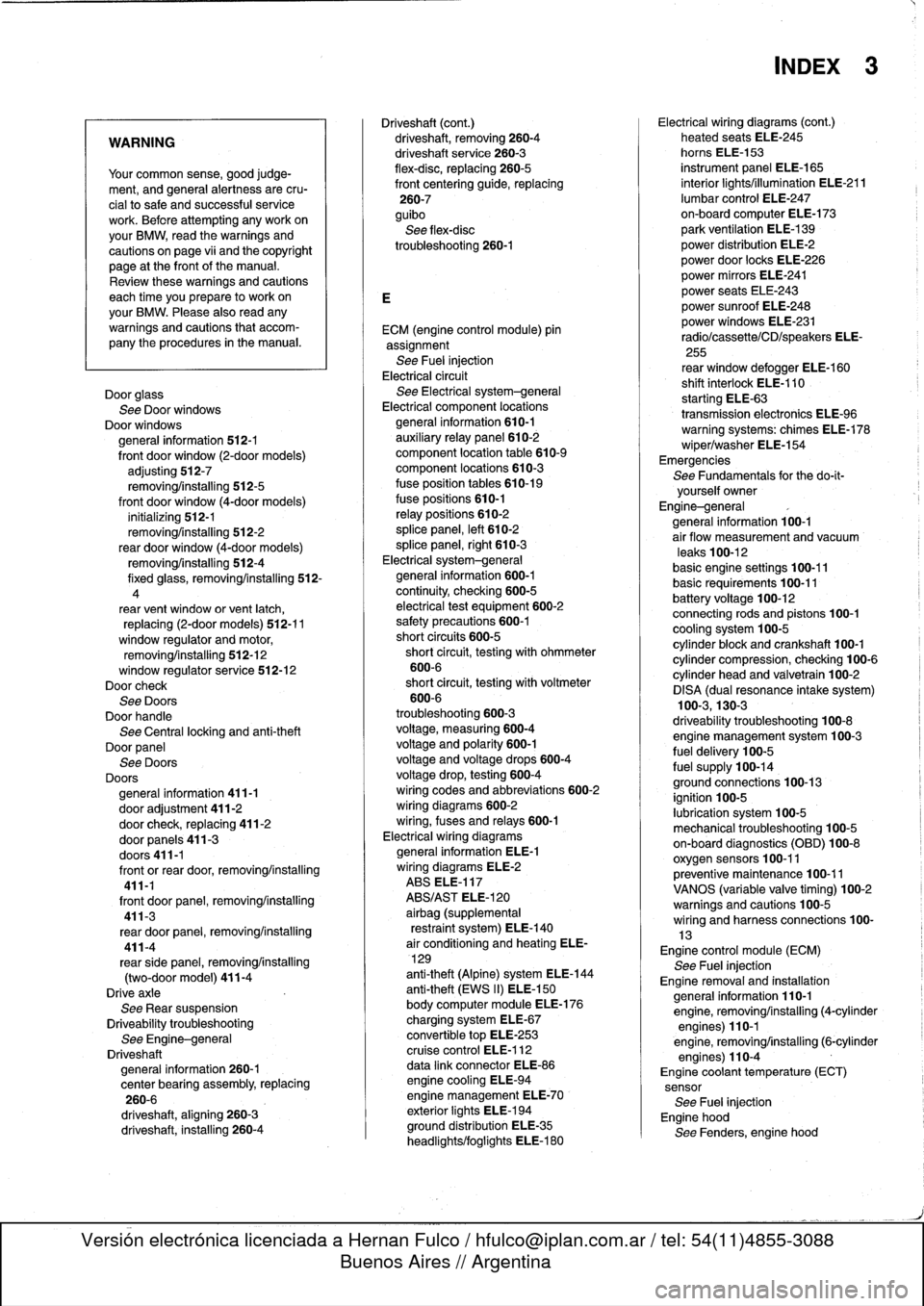
WARNING
Your
common
sense,
good
judge-
ment,
and
general
alertness
are
cru-
cial
to
safe
and
successful
service
work
.
Befcre
attempting
any
work
on
your
BMW,
read
the
warnings
and
cautions
on
page
vi¡
and
the
copyright
page
at
the
frontof
the
manual
.
Review
these
warnings
and
cautions
each
time
you
prepare
to
workon
your
BMW
.
Please
also
read
any
warnings
and
cautions
that
accom-
pany
the
procedures
in
the
manual
.
Door
glass
See
Door
windows
Door
windows
general
information
512-1
front
door
window
(2-door
models)
adjusting
512-7
removing/installing
512-5
front
door
window
(4-door
models)
initíalizing
512-1
removing/installing
512-2
rear
door
window
(4-door
models)
removing/installing
512-4
fixed
glass,
removing/installing
512-
4
rear
vent
window
or
vent
latch,
replacing
(2-door
models)
512-11
window
regulator
and
motor,
removing/installing
512-12
window
regulator
service
512-12Doorcheck
See
DoorsDoor
handle
See
Centrallocking
and
anti-theft
Door
panel
See
Doors
Doors
general
information
411-1
door
adjustment
411-2door
check,
replacing
411-2
door
panels
411-3
doors411-1
front
orrear
door,removing/installing
411-1
front
door
panel,
removing/installing
411-3
rear
door
panel,
removing/installing
411-4
rearsidepanel,
removing/installing
(two-door
model)
411-4
Drive
axle
See
Rear
suspension
Driveability
troubleshooting
See
Engine-general
Driveshaft
general
information
260-1
center
bearing
assembly,
replacing
260-6
driveshaft,
aligning
260-3
driveshaft,
installing
260-4
Driveshaft
(cont
.)
driveshaft,
removing260-4
driveshaftservice
260-3
flex-disc,
replacing
260-5
front
centering
guide,
replacing
260-7
guibo
See
flex-disc
troubleshooting260-1
ECM
(engine
control
module)
pin
assignment
See
Fuel
injection
Electrical
circuit
See
Electrical
system-general
Electrical
component
locations
general
information
610-1
auxíliary
relay
panel
610-2
component
location
table
610-9
component
locations
610-3
fuse
position
tables
610-19
fuse
positions
610-1
relay
positions
610-2
splice
panel,
left
610-2
splice
panel,
right
610-3
Electrical
system-general
general
information
600-1
continuity,
checking
600-5
electrical
test
equipment
600-2
safety
precautions
600-1
short
circuits
600-5
short
circuit,
testing
with
ohmmeter
600-6
short
circuit,
testing
with
voltmeter
600-6
troubleshooting
600-3
voltage,
measuring600-4
voltage
and
polarity
600-1
voltage
and
voltage
drops
600-4
voltage
drop,
testing
600-4
wiring
codes
and
abbreviations
600-2
wiring
diagrams
600-2
wiring,
fuses
and
relays
600-1
Electrical
wiring
diagrams
general
information
ELE-1
wiring
diagrams
ELE-2
ABS
ELE-117
ABS/AST
ELE-120
airbag
(supplemental
restraint
system)
ELE-140
air
conditioning
and
heating
ELE-
129
anti-theft
(Alpine)
system
ELE-144
anti-theft
(EWS
II)
ELE-150
body
computer
module
ELE-176
charging
system
ELE-67
convertible
top
ELE-253
cruise
control
ELE-112
data
link
connector
ELE-86
engine
cooling
ELE-94
engine
management
ELE-70
exterior
lights
ELE-194
ground
distribution
ELE-35
headlights/foglights
ELE-180
INDEX
3
Electrical
wiring
diagrams
(cont
.)
heated
seats
ELE-245
horns
ELE-153
instrument
panel
ELE-165
interior
lights/illumination
ELE-211
lumbar
control
ELE-247
on-board
computer
ELE-173
park
ventilation
ELE-139
power
distribution
ELE-2
power
door
locks
ELE-226
power
mirrors
ELE-241
power
seats
ELE-243
power
sunroof
ELE-248
power
windows
ELE-231
radio/cassette/CD/speakers
ELE-
255
rear
window
defogger
ELE-160
shift
interlock
ELE-110
starting
ELE-63
transmission
electronics
ELE-96
warning
systems`
.
chimes
ELE-178
wiper/washer
ELE-154
Emergencies
See
Fundamentals
for
the
do-it-
yourself
owner
Engine-general
general
information
100-1
air
flow
measurement
and
vacuum
leaks
100-12
basic
engine
settings
100-11
basic
requirements
100-11
battery
voltage
100-12connecting
rods
and
pistons
100-1
cooling
system
100-5
cylinder
block
and
crankshaft100-1
cylinder
compression,
checking
100-6
cylinder
head
and
valvetrain
100-2
DISA
(dual
resonance
intake
system)
100-3,130-3
driveability
troubleshooting
100-8
engine
management
system
100-3
fuel
delivery
100-5
fuel
supply
100-14ground
connections
100-13
ignition
100-5
lubrication
system100-5
mechanical
troubleshooting
100-5
on-board
diagnostics
(OBD)
100-8
oxygen
sensors
100-11
preventive
maintenance
100-11
VANOS
(variable
valve
timing)
100-2warningsand
cautions
100-5
wiring
andharness
connections100-
13Engine
control
module
(ECM)
See
Fuel
injection
Engine
removal
and
installation
general
information
110-1
engine,
removing/installing(4-cylinder
engines)
110-1
engine,
removing/installing
(6-cylinder
engines)
110-4
Engine
coolant
temperature
(ECT)
sensor
See
Fuel
injection
Engine
hood
See
Fenders,
enginehood
Page 753 of 759
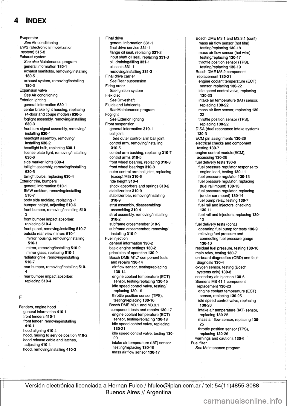
4
INDEX
Evaporator
See
Air
conditioning
EWS
(Electronic
immobilization
system)
515-8
Exhaust
system
See
also
Maintenance
program
general
information
180-1
exhaust
manifolds,
removingAnstalling
180-5
exhaustsystem,
removing/installing
180-3
Expansion
valve
See
Air
conditioning
Exterior
lighting
general
information
630-1
center
brake
light
housing,
replacing
(4-door
and
coupe
models)
630-5
foglight
assembly,
removing/installing
630-3
front
turn
signal
assembly,
removing/
installing
630-4
headlight
assembly,removing/
installing
630-2
headlight
bulb,
replacing
630-1
license
plate
light,
removing/installing
630-6
side
marker
lights
630-4
taillight
assembly,
removing/installing
630-5
taillight
bulbs,
replacing
630-4
Exterior
trim,
bumpers
general
information
510-1
BMW
embiem,
removing/installing
510-7
body
side
molding,
replacing
-7
bumper
height,
adjusting
510-6
front
bumper,
removing/installing
510-3
front
bumper
impact
absorber,
replacing
510-4
front
panel,
removing/installing
510-7
outside
rear
view
mirrors
510-1
mirror
housing,
removing/installing
510-1
mírror,
removing/installing
510-2
mirror
glass,
replacing
510-1
radiator
grille,
removing/installing
510-7
rear
bumper,
removingfinstalling
510-
4
rear
bumper
impact
absorber,
replacing
510-4
F
Fenders,
engine
hood
general
information
410-1
front
fenders
410-1
front
fender,
removing/installing
410-1
hood
aligning
410-4
hood,
raising
to
service
position
410-2
hood
release
cable
and
latches,
adjusting
410-4
hood,
removing/installing
410-3
Finaldrive
general
information
331-1
final
drive
se
rvice
331-1
flange
oil
sea¡,
replacing
331-2
inputshaft
oil
sea¡,
replacing
331-3
oil,
draining/filling
331-1
oil
seals331-1
removing/installing
331-3
Final
drive
carrier
See
Rear
suspension
Firing
order
See
Ignition
system
Flexdisc
See
DriveshaftFluids
and
lubricants
See
Maintenance
program
Foglight
See
Exterior
lighting
Front
suspension
general
information
310-1
ball
joint
See
outer
control
arm
ball
joint
control
arm,
removing/installing
310-5
control
arm
bushing,
replacing
310-7
control
arms
310-5
front
wheel
bearing,
replacing
310-8
front
wheel
bearings
310-8
outer
control
arm
ball
joint,
replacing
(except
M3)310-6
ride
height
310-4shock
absorbers
and
springs
310-2
stabilizer
bar
310-9
stabilizer
bar,
removing/installing
310-9
strut
assembly,disassembling/
assembling310-4
strut
assembly,
removing/installing
310-2subframe
crossmember
310-9subframe
crossmember,
removing/
installing
310-9
Fuel
injection
general
information
130-2
basic
engine
settings
130-2
principies
of
operatínn
130-2
Bosch
DME
Ml
.7
component
tests
and
repairs
130-14
air
floiv
sensor,testing/replacing
130-14
engine
coolant
temperature
(ECT)
sensor,
testing/replacing
130-15
¡dle
speed
control
valve,
testing/
replacing
130-16
throttle
position
sensor
(TPS),
testing/replacing
130-16
Bosch
DME
M3
.1
and
M3
.3
.1
component
tests
and
repairs
130-17
engine
coolant
temperature
(ECT)
sensor,
testing/replacing
130-18
¡dle
speed
control
valve,
replacing
130-21
¡dle
speed
control
valve,
testing
130-
20
intake
air
temperature
(IAT)
sensor,
testing/replacing
130-19
mass
air
flow
sensor130-17
Bosch
DME
M3
.1
and
M3
.3.1
(cont)
mass
air
flow
sensor
(hot
film)
testing/replacing
130-18
mass
air
flow
sensor
(hot
wire)
testing/replacing
130-17
throttle
position
sensor
(TPS),
testing/replacing
130-19
Bosch
DME
M5
.2
component
replacement
130-21engine
coolant
temperature
(ECT)
sensor,
replacing
130-22
ldle
speed
control
valve,
replacing
130-23
intake
air
temperature
(IAT)
sensor,
replacing
130-22
mass
air
flow
sensor,
replacing
130-
22
throttle
position
sensor
(TPS),
replacing
130-22
DISA
(dual
resonance
intake
system)
130-3
ECM
pin
assignments130-26
electrical
checks
andcomponent
testing
130-7engine
control
module(ECM),
accessing
130-26
fuel
delivery
tests
130-9
fuel
pressure
regulator
response
to
engine
load,
testing
130-11
fuel
pressure
regulator
130-13
fuel
pressure
regulator,
replacing
(fuel
rail
mount)130-13
fuel
pressure
regulator,
replacing
(under
car
mount)130-14
fuel
pump
relay,
testing
130-7
fuel
rail
and
injectors,
checking
130-11
fuel
rail
and
injectors,
replacing
130-
12
fuel
delivery
tests
(cont
.)
operatíng
fuel
pump
for
tests
130-9
relieving
fuel
pressure
and
connecting
fuel
pressure
gauge
130-10
residual
fuel
pressure,
testing
130-10
main
relay,
testing
130-7on-board
diagnostics
(OBD)
and
fault
diagnosis
130-4
oxygen
sensor,
testing
(Bosch
systems
only)
130-8
secondary
air
injection
130-5
Siemens
MS
41
.1
component
replacement
130-23
engine
coolant
temperature
(ECT)
sensor,
replacing
130-25
¡dle
speed
control
valve,
replacing
130-26
lntake
air
temperature
(IAT)
sensor,
replacing
130-25
mass
air
flow
sensor,
replacing
130-
25
throttle
position
sensor
(TPS),
replacing
130-26warnings
and
cautions
130-6
Fuel
filter
See
Maintenance
program