300 BMW 323i 1995 E36 User Guide
[x] Cancel search | Manufacturer: BMW, Model Year: 1995, Model line: 323i, Model: BMW 323i 1995 E36Pages: 759
Page 79 of 759
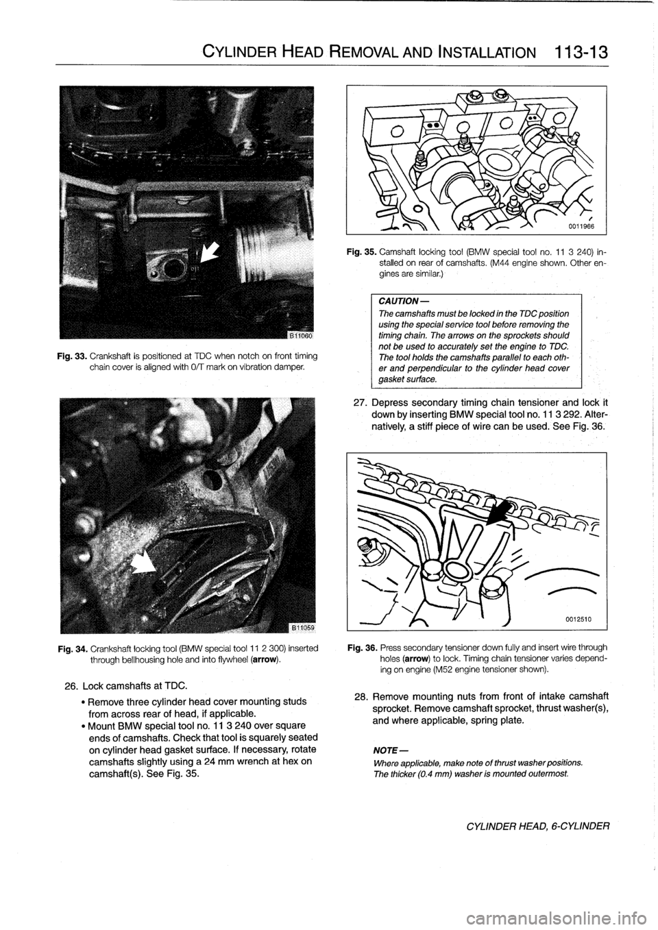
Fig
.
33
.
Crankshaft
is
positioned
at
TDC
when
notch
oh
front
timing
chain
cover
is
alignedwith
0/T
mark
on
víbration
damper
.
CYLINDER
HEAD
REMOVAL
AND
INSTALLATION
113-
1
3
Fig
.
35
.
Camshaft
locking
tool
(BMW
special
tool
no
.
11
3
240)
in-
stalled
on
rear
of
camshafts
.
(M44
engine
shown
.
Other
en-
gines
are
similar
.)
CAUTION-
The
camshafts
must
be
locked
in
the
TDC
position
using
the
special
service
tool
before
removing
the
timing
chain
.
Thearrowson
the
sprockets
should
not
be
used
to
accurately
set
the
engine
to
TDC
.
The
tool
holds
the
camshafts
parallel
to
each
oth-
er
and
perpendicular
to
the
cylinder
head
covergasket
surface
.
27
.
Depress
secondary
timing
chain
tensioner
and
lock
t
down
by
inserting
BMW
special
tool
no
.
113
292
.
Alter-
natively,
a
stiff
piece
of
wire
can
be
used
.
See
Fig
.,36
.
Fig
.
34
.
Crankshaft
locking
tool
(BMW
special
tool
11
2
300)
inserted
Fig
.
36
.
Press
secondary
tensioner
down
fully
and
insert
wire
through
through
bellhousinghole
and
finto
flywheel
(arrow)
.
holes
(arrow)
to
lock
.
Timingchain
tensioner
varies
depend-
ing
on
engine
(M52
engine
tensioner
shown)
.
26
.
Lockcamshafts
at
TDC
.
"
Remove
three
cylinder
head
cover
mounting
studs
28
.
Remove
mounting
nuts
from
front
of
intake
camshaft
from
across
rear
of
head,
if
applicable
.
sprocket
.
Remove
camshaft
sprocket,
thrust
washer(s),
"
Mount
BMW
special
tool
no
.
11
3
240
over
square
and
where
applicable,
spring
plate
.
ends
of
camshafts
.
Check
that
tool
is
squarely
seated
on
cylinder
head
gasket
surface
.
If
necessary,
rotate
NOTE-
camshafts
slightly
using
a
24
mm
wrench
at
hexon
Where
applicable,
make
note
of
thrust
washer
positions
.
camshaft(s)
.
See
Fig
.
35
.
The
thicker
(0
.4
mm)
washer
is
mounted
outermost
.
CYLINDER
HEAD,6-CYLINDER
Page 81 of 759
NOTE-
Cylinder
head,
installing
(6-cylinder
engine)
CAUTION-
If
the
camshafts
were
removed
and
installed
while
the
cylinder
head
was
off,
a
minimum
waiting
time
is
required
after
ínstalling
the
camshafts
.
When
the
camshaftsareremoved,
the
hydraullc
lifters
can
expand
.
This
expansion
can
cause
increased
valve
lift
when
the
camshafts
are
bolted
down,
re-
sulting
in
open
valves
.
Cylinder
head
installation
waiting
times
"
68°F
(20°C)
and
higher
.
.
.
..
..........
10
minutes
"
50-68°F
(10-20°C)
........
..
.........
30
minutes
"
32-50°F
(0-10
°C)
.........
...
........
75
minutes
CYLINDER
HEAD
REMOVAL
AND
INSTALLATION
113-
1
5
1
.
Clean
cylinder
head
and
gasket
surfaces
of
cylinder
block
and
al¡
timing
chain
covers
.
"
Remove
all
foreign
matter
and
any
¡¡quid
from
bolt
holes,
then
clean
with
a
thread
chaser
.
CA
UTION-
Do
not
use
ametal
scraper
or
wire
brush
to
clean
the
aluminum
cylinder
head
or
pistons
.
If
neces-
sary,
use
a
hard
wooden
or
plastic
scraper
.
Also
available
are
abrasive
discs
to
be
used
in
conjunc-
tion
with
an
electric
drill
.
Be
sure
to
use
the
correct
disc
for
the
typeof
metal
being
cleaned
.
2
.
Check
gasket
surface
of
cylinder
head
and
cylinder
block
for
warpage
using
a
straight
edge
.
NOTE-
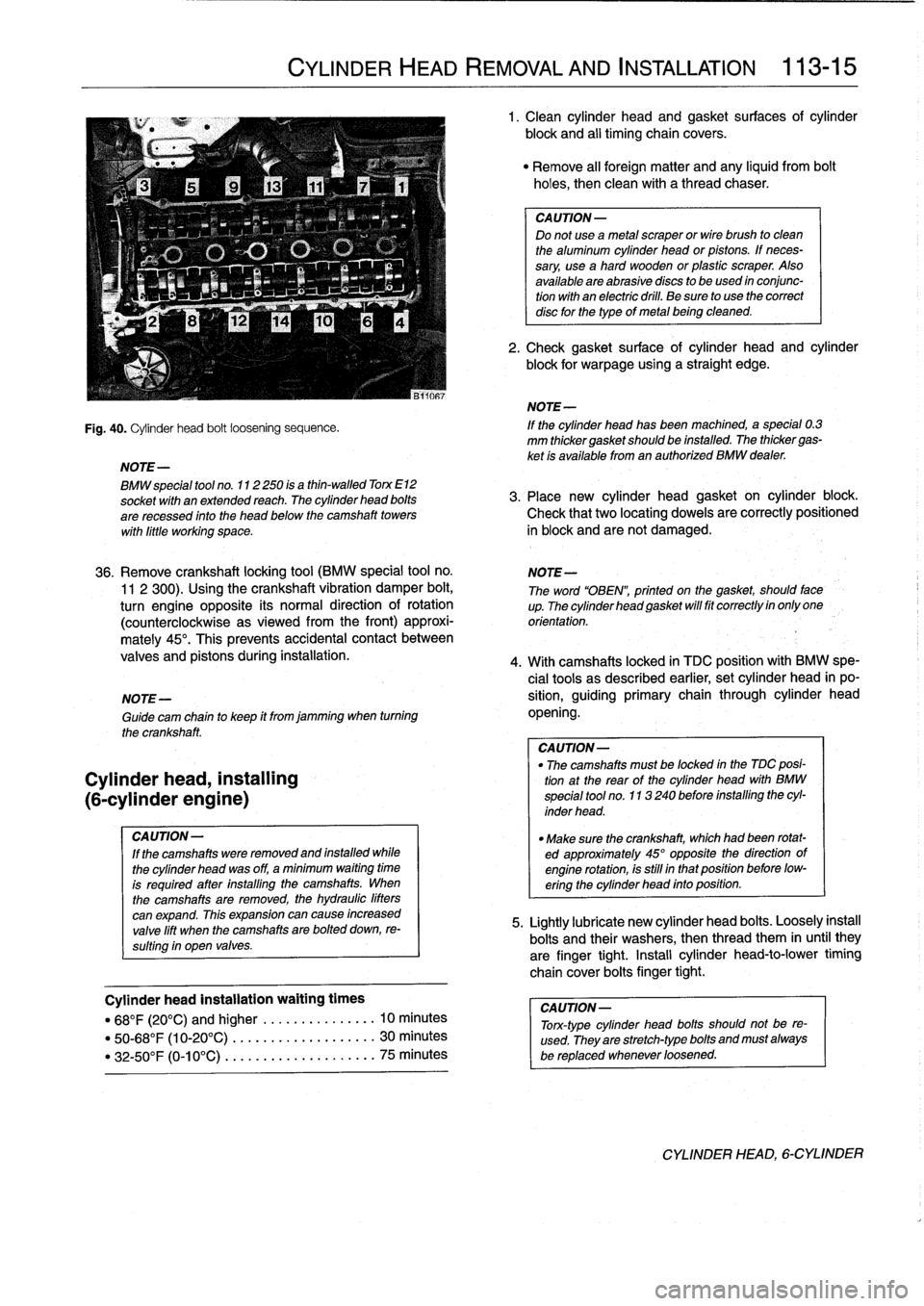
Fig
.
40
.
Cylinder
head
bolt
loosening
sequence
.
If
the
cylinder
head
has
been
machined,a
special
0
.3
mm
thickergasketshould
be
installed
.
The
thickergas-
ket
is
available
from
an
authorized
BMW
dealer
.
BMW
special
tool
no
.
112250
is
a
thin-walled
Torx
E12
socket
wíth
anextended
reach
.
The
cylinder
head
bolts
3
.
Place
new
cylinder
head
gasket
on
cylinder
block
.
are
recessed
finto
the
head
below
the
camshaft
towers
Check
that
two
locating
dowels
are
correctly
positioned
wíth
liffle
working
space
.
in
block
and
arenot
damaged
.
36
.
Remove
crankshaft
locking
tool
(BMW
special
tool
no
.
NOTE-
11
2
300)
.
Using
the
crankshaft
vibration
damper
bolt,
The
word
"OBEN",
printed
on
the
gasket,
should
face
turn
engine
opposite
its
normal
direction
of
rotation
up
.Thecylinderheadgasketwillfitcorrectlyinonlyone
(counterclockwise
asviewed
from
the
front)
approxi-
orientation
.
mately
45°
.
This
prevents
accidental
contact
between
valves
and
pistons
during
installation
.
4
.
With
camshafts
locked
in
TDC
positionwith
BMW
spe-
cial
tools
as
described
earlier,
set
cylinder
head
in
po
NOTE-
sition,
guiding
primary
chain
through
cylinder
head
Guide
cam
chain
to
keep
it
from
jamming
when
turning
opening
.
the
crankshaft
.
CA
UTION-
"
The
camshafts
must
be
locked
in
the
MC
posi-
tion
at
the
rear
of
the
cylinder
head
with
BMW
special
tool
no
.
113240
before
installing
the
cyl-
inder
head
.
"
Make
sure
the
crankshaft,
which
had
been
rotat-
ed
approximately
45°
opposite
thedirection
of
engine
rotation,is
still
in
that
position
before
low-
ering
the
cylinder
head
into
position
.
5
.
Lightly
lubricate
new
cylinder
head
bolts
.
Loosely
instan
bolts
and
their
washers,
then
thread
them
in
until
they
are
finger
tight
.
Install
cylinder
head-to-lower
timing
chaincover
boitsfinger
tight
.
CAUTION-
Tonc-type
cylinder
head
bolts
should
not
be
re-
used
.
They
are
stretch-typebolts
and
must
always
be
replaced
whenever
loosened
.
CYLINDER
HEAD,
6-CYLINDER
Page 82 of 759
113-16
CYLINDER
HEAD
REMOVAL
AND
INSTALLATION
NOTE-
Check
that
all
washers
for
the
cylinder
head
bolts
are
in
place
before
installlng
the
bolts
.
Some
of
the
washers
may
be
staked
to
the
cylinder
head
.
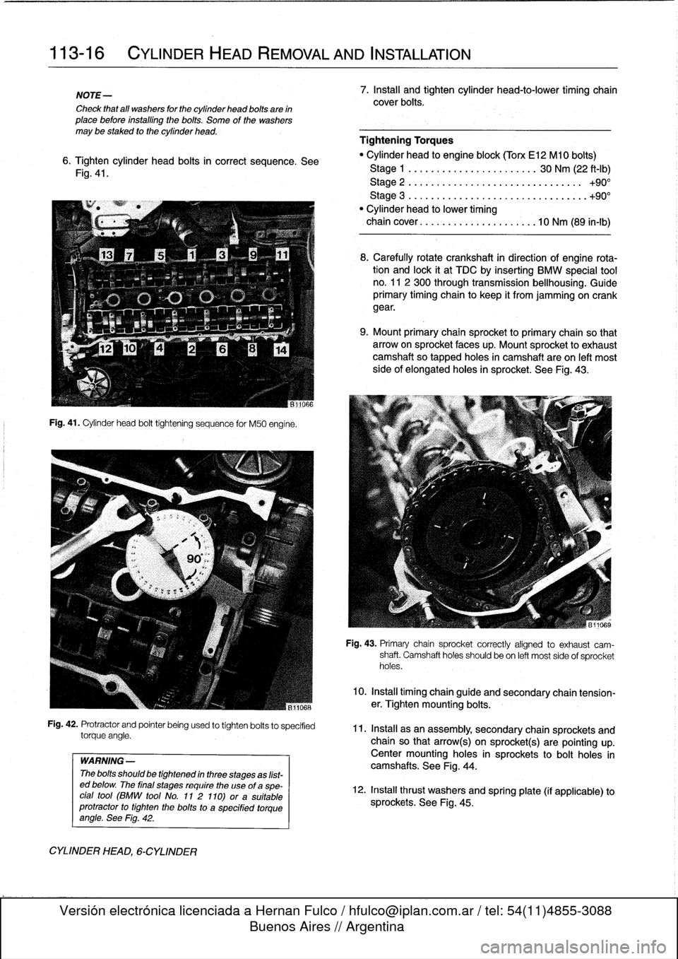
6
.
Tighten
cylinder
head
bolts
in
correct
sequence
.
See
Fig
.
41
.
Fig
.
41
.
Cylinder
head
bolt
tightening
sequence
for
M50
engine
.
Fig
.
42
.
Protractor
and
pointer
being
used
to
tighten
bolts
to
specified
torque
angle
.
WARNING
-
The
bolts
should
be
tightened
in
three
stages
as
list-
ed
below
.
The
final
stages
require
the
use
of
aspe-
cial
tool
(BMW
tool
No
.
11
2
110)
ora
suitable
protractor
to
tighten
the
bolts
to
a
specified
torque
angle
.
See
Fig
.
42
.
CYLINDER
HEAD,
6-CYLINDER
7
.
Install
and
tighten
cylinder
head-to-lower
timing
chain
cover
bolts
.
Tightening
Torques
"
Cylinder
head
to
engine
block(Torx
El
2
Ml
0
bolts)
Stage
1
.........
..
.
.
.
...
.
...
..
30
Nm
(22
ft-Ib)
Stage
2
.........
..
..
....
.
...
..........
+90°
Stage
3
...
.
.....
..
.
.
.
...
.
...
..........
.+90°
"
Cylinder
head
lo
lower
timing
chaincover
.......
..
..
..
...
.
....
10
Nm
(89
in-lb)
8
.
Carefully
rotate
crankshaft
in
direction
of
engine
rota-tion
and
lock
it
at
TDC
by
inserting
BMW
special
tool
no
.
11
2
300
through
transmission
bellhousing
.
Guide
primary
timing
chain
to
keep
it
from
jamming
on
crank
gear
.
9
.
Mount
primary
chain
sprocketto
primary
chain
so
that
arrowon
sprocket
faces
up
.
Mount
sprocket
to
exhaust
camshaftso
tapped
holes
in
camshaft
are
on
left
most
side
of
elongated
holes
in
sprocket
.
See
Fig
.
43
.
Fig
.
43
.
Primary
chain
sprocket
correctly
afgned
to
exhaust
cam-
shaft
.
Camshaft
holes
should
be
on
left
most
sideof
sprocket
holes
.
10
.
Install
timing
chain
guide
and
secondary
chain
tension-er
.
Tighten
mounting
bolts
.
11
.
Install
asan
assembly,
secondary
chain
sprockets
and
chain
so
that
arrow(s)
on
sprockt(s)
are
pointing
up
.
Centermounting
holes
in
sprockets
tobolt
holes
in
camshafts
.
See
Fig
.
44
.
12
.
Install
thrust
washers
and
spring
plate
(if
applicable)
to
sprockets
.
See
Fig
.
45
.
Page 88 of 759
116-
4
CYLINDER
HEAD
AND
VALVETRAIN
NOTE-
"
The
camshaft
bearing
caps
are
coded
with
a
letter
anda
number
.
Forexample,
'541"is
the
exhaustcam-
shaft
bearing
cap
at
the
front
of
the
engine,
and
`El"
is
the
intake
camshaft
bearing
cap
at
the
front
of
the
engine
.
"
Camshafts
are
stamped
with
a
code
letter-'E"
for
the
intakeside
and
A"
for
the
exhaust
side
.
"
"E"
isfor
Einla3,
(German
for
intake)
and
A"
is
for
Auspuff,
(Germen
for
exhaust)
.
"
The
front
of
the
engine
is
at
the
front
of
the
car
.
8
.
Camshaft
installation
is
reverse
of
removal,
noting
the
following
:
"
Prior
to
installation,
check
all
components
for
wear
as
described
below
underCylinder
Head
and
Val-
vetrain
Reconditioning
.
"
Lubricate
camshafts
prior
to
installation
.
"
Reinstall
timing
chain
sprockets
and
tensioner
and
set
valve
timing
before
reinstalling
rocker
arms,as
spe-
cifically
described
in
117
Camshaft
Timing
Chain
.
"
Be
sure
corresponding
camshaft
lobe
is
pointing
up
before
installing
rocker
arms
.
Note
that
each
rocker
arm
angles
away
from
corresponding
spark
plug
hole
.
See
Fig
.
4
.
"
Wait
at
least
10
minutes
for
hydraulic
cam
followers
to
fully
compress
before
cranking
engine
over
with
start-
er
for
the
first
time
.
Tightening
Torques
"
Camshaft
bearing
caps
to
cylinder
head
(M7)
.............
15
Nm
(11
ft-Ib)
"
Cylinder
head
cover
to
cylinder
head
(M6)
.............
10
Nm
(89
in-lb)
"
Primary
timing
chain
tensioner
plug
to
cylinder
head
.
................
40
Nm
(30
ft-lb)
(sea
117
Camshaft
Timing
Chain)
"
Spark
plugs
(M12)
.............
...
23
Nm
(17
ft-lb
Timing
chaincover
(upper)
to
cylinder
head
M6
.....
.
.
...
................
.
10
Nm
(7
.5
ft-Ib)
M7
....
..
.
.
........
.
.....
.
...
.
15
Nm
(11
ft-Ib)
"
Timing
chain
sprockets
to
camshaft
M6
....
.
.
..
..............
.
..
..
10
Nm
(7
.5
ft-Ib)
M7
....
....
..............
.
..
..
.15
Nm
(11
ft
.lb)
(sea
117
Camshaft
Timing
Chain)
Camshafts,
removing
and
installing
(6-cylinder
engine)
Camshafts
on
6-cylinder
engines
can
be
removed
with
the
cylinder
head
mounted
on
the
engine
.
The
first
step
is
to
re-
move
the
cylinder
head
cover
.
See
113
Cylinder
Head
Re-
moval
and
Installation
.
CYLINDER
HEAD,
DISASSEMBLYAND
ASSEMBLY
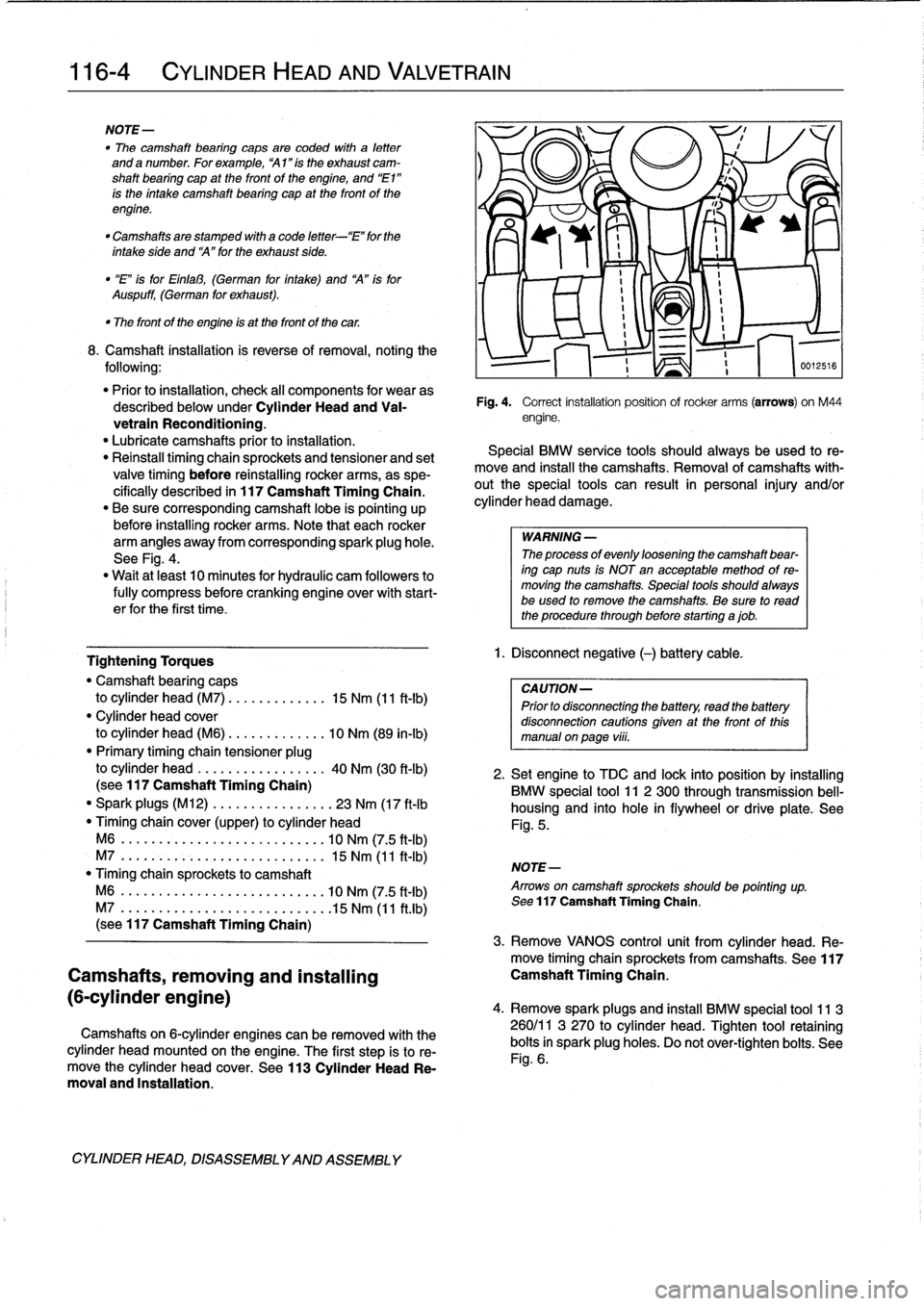
Fig
.
4
.
Correct
installation
position
ofrocker
arms
(arrows)
on
M44
engine
.
Special
BMW
service
tools
should
always
be
used
to
re-
move
and
instan
the
camshafts
.
Removal
of
camshafts
with-
outthe
special
tools
can
result
in
personal
injury
and/or
cylinder
head
damage
.
WARNING
-
The
processof
evenly
loosening
the
camshaft
bear-
ing
cap
nuts
is
NOT
en
acceptable
method
of
re-
moving
the
camshafts
.
Special
tools
shouldalways
be
used
lo
remove
the
camshafts
.
Be
sure
to
read
the
procedure
through
before
starting
ajob
.
1
.
Disconnect
negative
(-)
battery
cable
.
CAUTION-
Prior
to
disconnectiog
the
battery,
read
the
battery
disconnection
cautions
given
at
the
front
of
this
manual
onpaga
viii
.
516
2
.
Setengine
to
TDC
and
lock
into
position
by
installing
BMW
special
tool
11
2
300
through
transmission
bell-
housing
and
into
hole
in
flywheel
or
drive
platea
See
Fig
.
5
.
NOTE-
Arrows
on
camshaft
sprockets
shouldbe
pointing
up
.
Sea
117
Camshaft
Timing
Chain
.
3
.
Remove
VANOS
control
unit
from
cylinder
head
.
Re-
move
timing
chainsprockets
from
camshafts
.
See117
Camshaft
Timing
Chain
.
4
.
Remove
sparkplugs
and
insta¡¡
BMW
special
tool
11
3
260/11
3
270
to
cylinder
head
.
Tighten
tool
retaining
bolts
in
spark
plug
holes
.
Do
not
ovar-tighten
bolts
.
See
Fig
.
6
.
Page 89 of 759
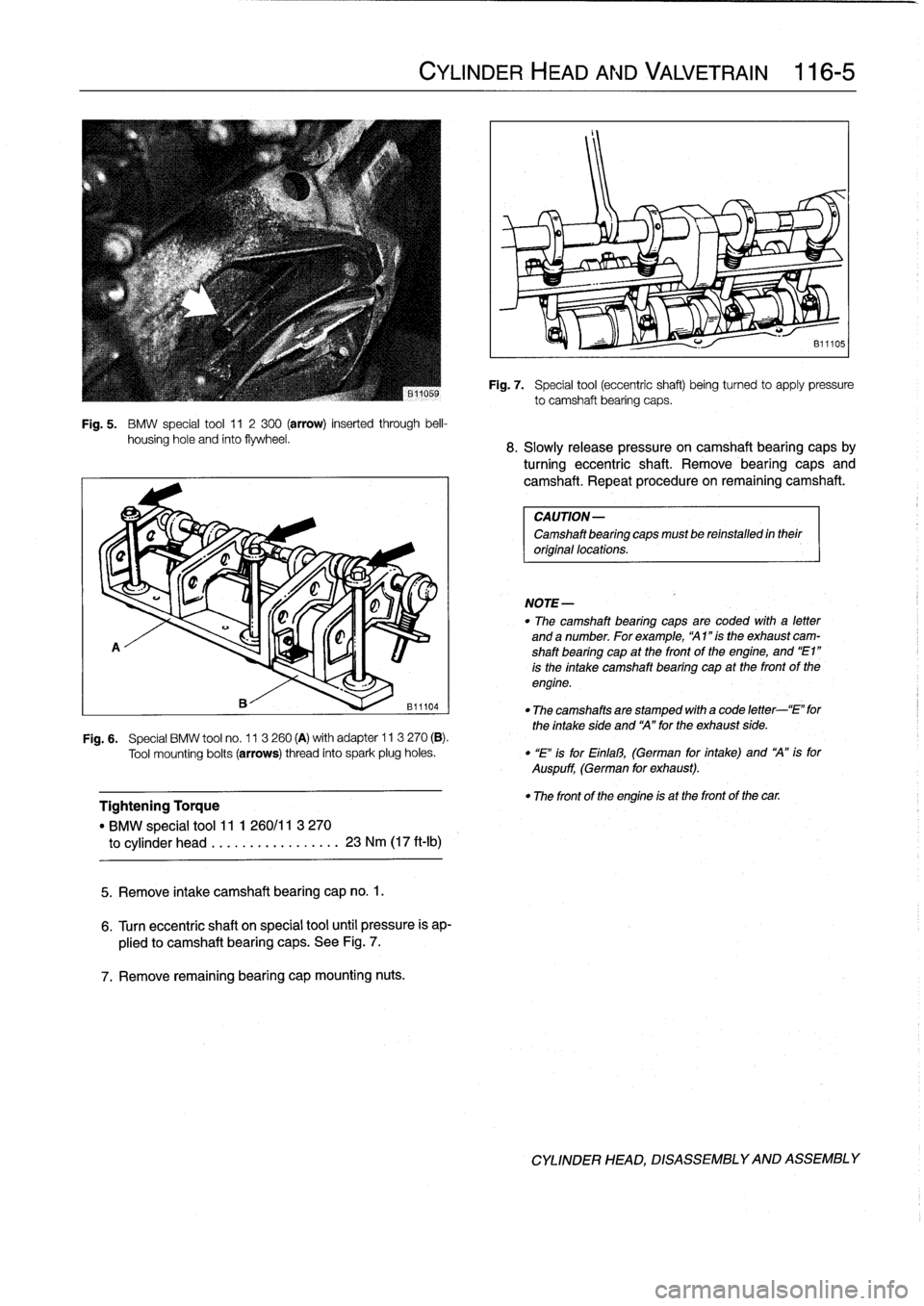
Fig
.
5
.
BMW
special
tool
11
2300
(arrow)
inserted
through
bell-
housing
hole
and
finto
flywheel
.
A
Tightening
Torque
"
BMW
special
tool11
1
260/11
3
270
to
cylinder
head
.................
23
Nm
(17
ft-Ib)
5
.
Remove
intake
camshaft
bearing
cap
no
.
1
.
6
.
Turn
eccentric
shaft
on
special
tool
until
pressure
is
ap-
plied
to
camshaft
bearing
caps
.
See
Fig
.
7
.
7
.
Remove
remaining
bearing
capmounting
nuts
.
CYLINDER
HEAD
AND
VALVETRAIN
116-
5
NOTE-
Fig
.
7
.
Special
tool
(eccentric
shaft)
beingturned
to
apply
pressure
to
camshaft
bearing
caps
.
8
.
Slowly
release
pressure
oncamshaft
bearing
capsby
turning
eccentric
shaft
.
Remove
bearing
caps
and
camshaft
.
Repeat
procedure
on
remaining
camshaft
.
CAUTION-
Camshaft
bearing
capsmust
be
reinstalled
in
their
original
locations
.
"
The
camshaft
bearing
caps
are
coded
with
a
letter
and
a
number
.
For
example,
`A1
"is
the
exhaust
cam-
shaft
bearing
cap
at
the
front
of
the
engine,
and
"E1"
is
the
intake
camshaft
bearing
cap
at
the
front
of
the
engine
.
"
The
camshaftsare
stamped
with
a
code
letter-`E"
for
the
intake
síde
and
`A"
for
the
exhaust
side
.
F19
.6
.
Special
BMW
tool
no
.
11
3260
(A)
with
adapter
ll
3
270
(B)
.
Tool
mounting
bolts
(arrows)
thread
into
spark
plug
holes
.
"
"E"
is
for
Einfal3,
(German
for
intake)
and
`A"
is
for
Auspuff,
(German
for
exhaust)
.
"
The
front
of
the
engine
is
at
the
front
of
the
car
.
CYLINDER
HEAD,
DISASSEMBLYAND
ASSEMBLY
Page 99 of 759
NOTE-
The
vibration
damper
center
bolt
is
very
tight
.
A
heavy
duty
holding
device,
such
as
BMW
special
tool
no
.
112
150,
should
be
used
to
hold
the
vibration
damper
hub
V
stationary
while
the
bolt
is
loosened
.
v
11
.
Usingloosened
bolt
at
vibration
damper,
turn
crank-
shaft
to
TDC
and
lock
in
position
by
inserting
BMW
special
tool
no
.
11
2
300
through
transmission
bell-
-
p
housing
.
See
Fig
.
5
.
v
O
NOTE-
I\
0011966a
"
If
necessary,
remove
plugfrom
locating
boye
in
lower
edge
of
bell
housing
.
"
Confirm
that
locatng
tool
has
been
correctlyinstalled
by
trying
to
rotate
the
crankshaft
.
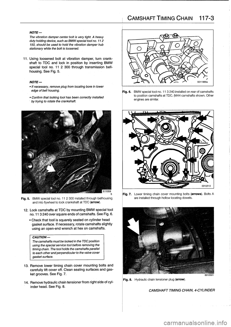
Fig
.
7
.
Lower
timing
chain
cover
mounting
bolts
(arrows)
.
Bolts
A
Fig
.
5
.
BMW
special
tool
no
.
11
2300
installed
through
bellhousing
are
installed
through
hollow
locating
dowels
.
and
finto
flywheel
to
lock
crankshaft
at
TDC
(arrow)
.
CA
UTION-
Thecamshafts
mustbe
locked
in
the
MC
position
using
the
specialservice
tool
before
removing
the
timing
chain
.
The
tool
holds
the
camshafts
parallel
to
each
other
and
perpendicular
to
the
valve
cover
gasket
surface
.
12
.
Lockcamshafts
at
TDC
bymounting
BMW
special
tool
no
.
113
240
over
square
ends
of
camshafts
.
See
Fig
.
6
.
"
Check
that
tool
is
squarely
seated
on
cylinder
head
gasket
surface
.
If
necessary,
rotate
camshafts
slightly
using
an
open-end
wrench
at
hexon
camshafts
.
13
.
Remove
lower
timing
chaincover
mounting
bolts
and
carefully
lift
cover
off
.
Clean
sealing
surfaces
and
gas-
ket
grooves
.
See
Fig
.
7
.
14
.
Remove
hydraulic
chaintensioner
from
right
side
of
cyl-
inder
head
.
See
Fig
.
8
.
CAMSHAFT
TIMING
CHAIN
117-
3
Fig
.
6
.
BMW
special
tool
no
.
11
3240
installed
on
rearof
camshafts
to
position
camshafts
at
TDC
.
(M44
camshafts
shown
.
Other
engines
are
similar
.
Fig
.
8
.
Hydraulic
chain
tensionerplug
(arrow)
.
CAMSHAFT
TIMING
CHAIN,
4-CYLINDER
Page 104 of 759
117-
8
CAMSHAFT
TIMING
CHAIN
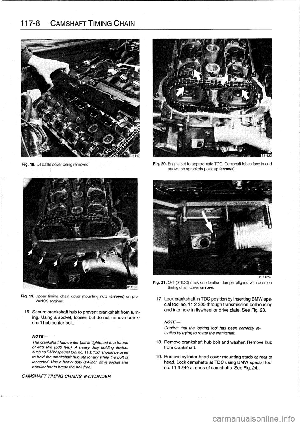
Fig
.
18
.
Oil
baffle'
cover
being
removed
.
Fig
.
19
.
Upper
timing
chaincover
mounting
nuts
(arrows)
on
pre-
VANOS
engines
.
16
.
Secure
crankshaft
hub
to
prevent
crankshaft
from
turn-
ing
.
Using
a
socket,
loosen
but
do
not
remove
crank-
shaft
hub
center
bolt
.
CAMSHAFT
TIMINGCHAINS,
6-CYLINDER
Fig
.
20
.
Engine
set
to
approximate
TDC
.
Camshaft
lobes
face
in
and
arrows
on
sprockets
point
up
(arrows)
.
B1
1123a
Fig
.
21
.
O/
T
(0°TDC)
mark
on
vibration
damper
aligned
with
boss
on
timing
chain
cover
(arrow)
.
17
.
Lock
crankshaft
in
TDC
position
by
inserting
BMW
spe-
cial
tool
no
.
11
2
300
through
transmissionbellhousing
and
into
hole
in
flywheelor
drive
plate
.
See
Fig
.
23
.
NOTE-
Confirm
that
the
locking
tool
has
been
correctly
in-
stalled
by
trying
to
rotate
the
crankshaft
.
NOTE-
The
crankshaft
hub
center
bolt
is
tightened
to
a
torque
18
.
Remove
crankshaft
hub
bolt
and
washer
.
Remove
hub
of
410
Nm
(300
ft-ib)
.
A
heavy
duty
holding
device,
from
crankshaft
.
suchas
BMW
special
tool
no
.
112150,
should
be
used
to
hold
the
crankshaft
hub
stationary
while
the
bolt
is
19
.
Remove
cylinder
head
cover
mounting
studs
at
rear
of
loosened
.
Use
a
heavy
duty
314-inch
drive
socket
and
head
.
Lock
camshafts
at
TDC
using
BMW
special
tool
breaker
bar
to
break
the
bolt
free
.
no
.
11
3
240
at
ends
of
camshafts
.
See
Fig
.
24
.
.
Page 105 of 759
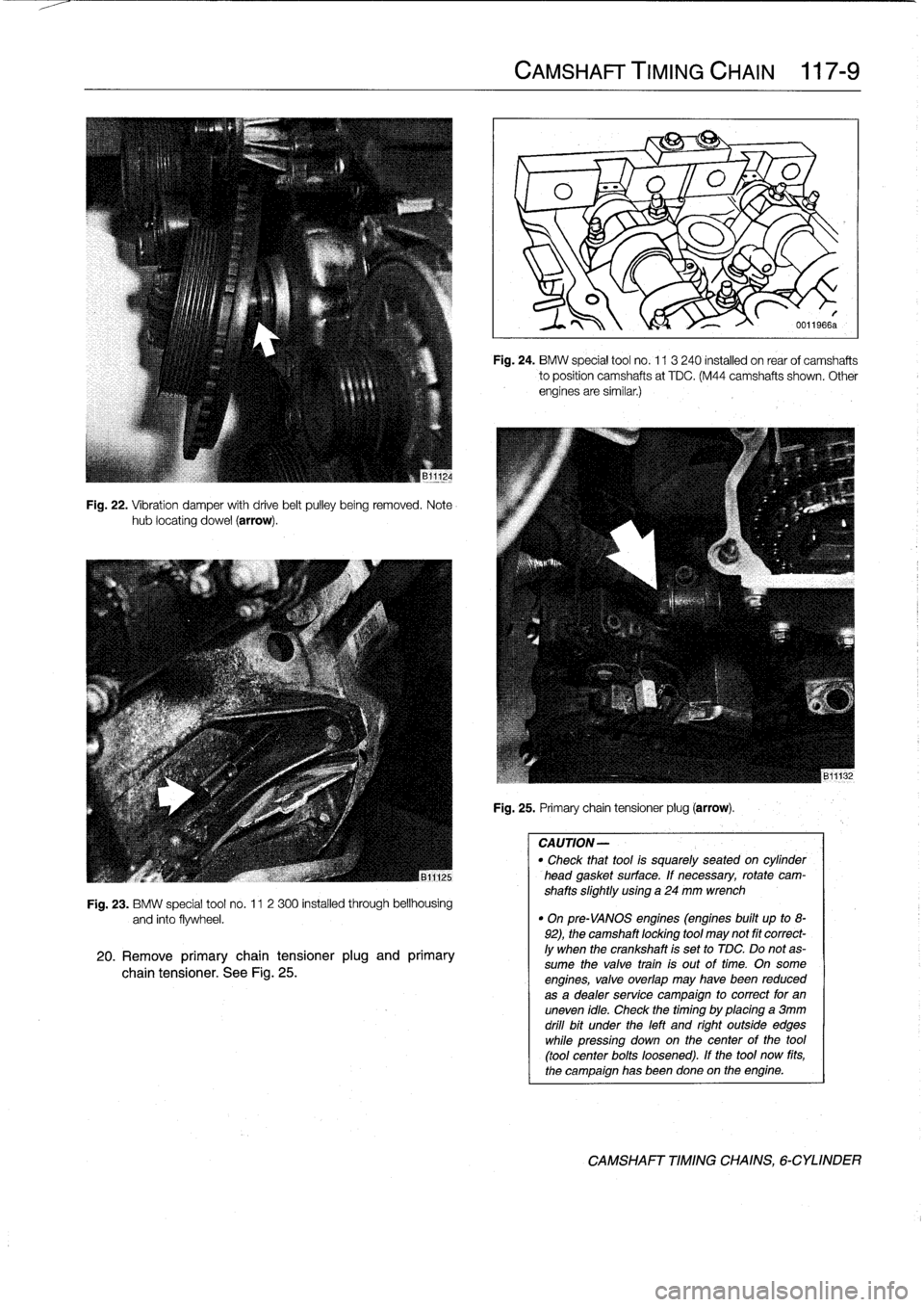
Fig
.
22
.
Vibration
damper
with
drive
belt
pulley
being
removed
.
Notehub
locating
dowel
(arrow)
.
Fig
.
23
.
BMW
special
tool
no
.
11
2
300
installed
through
bellhousing
and
into
flywheel
.
20
.
Remove
primary
chain
tensioner
plug
and
primary
chain
tensioner
.
See
Fig
.
25
.
CAMSHAFT
TIMING
CHAIN
117-
9
Fig
.
24
.
BMW
special
tool
no
.
113
240
installed
on
rear
of
camshafts
to
position
camshafts
at
TDC
.
(M44
camshafts
shown
.
Other
engines
are
similar
.)
Fig
.
25
.
Primary
chain
tensioner
plug
(arrow)
.
CAUTION-
"
Check
thattool
is
squarely
seated
on
cytinder
head
gasket
surface
.
If
necessary,
rotate
cam-
shafts
slightly
using
a
24
mm
wrench
"
On
pre-VANOS
engines
(engines
built
up
to
8-
92),
the
camshaft
locking
tool
may
not
fit
correct-
ly
when
the
crankshaft
is
set
to
TDC
.
Do
notas-
sume
the
valve
train
is
out
oftime
.
On
some
engines,
valve
overlap
may
havebeen
reduced
as
a
dealer
service
campaign
to
correct
for
an
uneven
idle
.
Check
thetiming
by
placing
a
3mm
drill
bit
under
the
left
and
right
outside
edges
while
pressíng
down
on
thecenter
of
the
tool
(tool
center
bolts
loosened)
.
If
the
tool
now
fits,
the
campaign
has
beendone
on
the
engine
.
CAMSHAFT
TIMING
CHAINS,
6-CYLINDER
Page 109 of 759
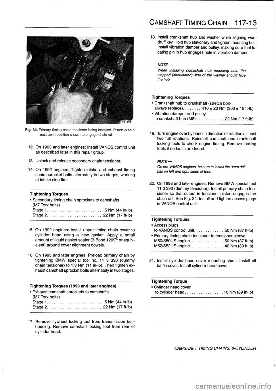
Fig
.
34
.
Primary
timíng
chain
tensioner
being
instafed
.
Pistoncutout
mustbe
in
position
shown
to
engage
chain
rail
.
12
.
On
1993
and
later
engines
:
Install
VANOS
control
unit
as
described
later
in
this
repair
group
.
13
.
Unlock
and
release
secondary
chaintensioner
.
NOTE-
On
pre-VANOS
engines,
be
sure
toinstall
the
3mm
drill
bits
on
left
and
right
sides
of
tool
.
14
.
On
1992
engines
:
Tighten
intake
and
exhaust
timing
chain
sprocket
bolts
alternately
in
two
stages,
working
at
intake
side
first
.
Tightening
Torques
"
Secondary
timing
chaira
sprockets
to
camshafts
(M7
Torx
bolts)
Stage
1
....
.
.
.
...
...............
5
Nm
(44
in-lb)
Stage
2
..
.
.
.
.
.
.
................
22
Nm
(17
ft-Ib)
15
.
On
1992
engines
:
Install
upper
timing
chaincover
to
cylinder
head
using
a
new
gasket
.
Apply
a
small
amount
ofliquid
gasket
sealer
(3-Bond
1209
®
orequiv-
alent)
around
coveralignment
dowels
.
16
.
On
1993
and
later
engines
:
Preloadprimary
chain
by
tightening
BMW
special
tool
no
.
11
3
390
(dummy
21
.
Install
cylinder
head
cover
mounting
studs
.
Insta¡¡
oil
chain
tensioner)
to
1
.3
Nm
(11
in-lb)
.
Then
tighten
ex-
baffle
cover
.
Install
cylinder
head
cover
.
haust
camshaft
sprocket
bolts
alternately
in
twostages
.
Tightening
Torques
(1993
and
later
engines)
"
Exhaust
camshaft
sprockets
to
camshafts
(M7
Torx
bolts)
Stage
1
..
...
..
..
................
5
Nm
(44
in-lb)
Stage
2
.....
.
.
...
..............
22
Nm
(17
ft-Ib)
17
.
Remove
flywheel
locking
tool
from
transmission
bell-
housing
.
Remove
camshaft
locking
tool
from
rear
of
cylinder
head
.
CAMSHAFT'TIMING
CHAIN
117-
1
3
18
.
Insta¡¡
crankshaft
hubandwasher
while
aligning
woo-
druff
key
.
Hold
hub
stationary
and
tighten
mounting
bolt
.
Install
vibration
damper
and
pulley,
making
sure
that
lo-
cating
pin
in
hub
engages
hole
in
vibration
damper
.
NOTE-
When
installing
crankshaft
hub
mounting
bolt,
the
stepped
(shouldered)
sideof
the
washer
should
fase
the
hub
.
Tightening
Torques
Crankshaft
hub
to
crankshaft
(stretch
bolt-
always
replace)
........
410
±
20
Nm
(300
±
15
ft-1b)
"
Vibration
damper
and
pulley
to
crankshaft
hub
(M8)
...
..
.
..
....
22
Nm
(17
ft-Ib)
19
.
Turn
engine
over
by
hand
in
direction
of
rotation
atleast
two
full
rotations
.
Reinstall
camshaft
and
crankshaft
locking
tools
to
check
engine
timing
.
Remove
locking
tools
if
no
faults
are
found
.
20
.
On
1993
and
later
engines
:
Remove
BMW
special
tool11
3
390
(dummy
tensioner)
.
Install
primary
chain
ten-sioner
so
that
cutout
in
tensioner
piston
engages
the
chain
rail
.
See
Fig
.
34
.
Install
and
tighten
access
plugs
in
VANOS
control
unit
.
Tightening
Torques
"
Access
plugs
to
VANOS
control
unit
..........
.
..
50
Nm
(37
ft-Ib)
"
Primary
timing
chain
tensioner
to
tensioner
sleeve
M50/S50US
engine
.......
.
..
..
.
.
50
Nm
(37
ft-Ib)
M52/S52US
engine
..........
..
.
.
40
Nm
(30
ft-Ib)
Tightening
Torque
"
Cylinder
head
cover
to
cylinder
head
............
...
.
.10
Nm
(89
in-lb)
CAMSHAFT
TIMINGCHAINS,
6-CYLINDER
Page 110 of 759
117-
1
4
CAMSHAFT
TIMING
CHAIN
22
.
Installation
of
remaining
parts
is
reverse
of
removal,
When
theengine
is
running,
the
piston
housing
is
supplied
noting
the
following
:
with
pressurized
engine
oil
.
At
idie,
the
solenoid
isin
the
off
"
When
installing
thermostat,
make
sure
arrow
or
vent
position
(de-energized)
and
valve
timing
is
maintained
in
the
hole
faces
up,
if
applicable
.
normal
position
:
When
the
solenoid
is
energized,
the
gear
cup
"
Refill
cooling
systemas
described
in
170
Radiator
piston
moves
forward
to
advance
the
camshaftby
a
maximum
and
Coming
System
.
of
12
.5
.
"
Install
oil
pan
as
described
in
119
Lubrication
Sys-
tem
.
"
Fill
engine
with
oil
and
install
a
new
oil
filter
as
de-
scribed
in
020
Maintenance
Program
.
"
Insta¡¡
ground
wires
at
cylinder
head
cover
mounting
studs
and
at
front
of
cylinder
head
and
thermostat
housing,
where
applicable
.
VANOS
system
operation,
testing
Tightening
Torques
There
are3
special
tools
required
to
check
VANOS
opera-
"
Coolant
drain
plugto
cylinder
block
.
.
25
Nm
(18
ft-Ib)
tion
;
an
electricaltest
lead
(BMW
special
tool
no
.
12
6
410),
an
"
Radiator
cooling
fan
to
coolant
pump
.
40
Nm
(30
ft-Ib)
air
line
fitting
(BMW
special
tool
no
.
11
3
450),
and
a
crank-
"
Radiator
drain
screw
to
radiator
...
.
2
.5
Nm
(22
in-Ib)
shaft
TDC
locking
tool
(BMW
special
tool
no
.
112
300)
.
"
Upper
timing
chaincover
to
cylinder
head
The
test
leal
is
used
to
power
the
solenoid,
simulating
the
M6
nut
...
.....
.............
..
.
10
Nm
(89
in-lb)
ground
signal
from
the
DME
control
unit
.
The
air
line
fitting
M8
bolt
.....
....
.
.
.............
22
Nm
(17
ft-Ib)
takes
the
place
of
the
oil
supply
line
fitting
to
simulate
oil
Ares-
"
VANOS
control
unit
to
cylinder
head
sure
.
The
locking
tool
positions
and
locks
the
crankshaft
at
M6
nut
.........
..
..
.
..........
10
Nm
(89
in-lb)
TDC,
cylinder
no
.
l.
M8
bolt
........
...
.............
22
Nm
(17
ft-Ib)
"
VANOS
oil
supply
pipe
to
VANOS
control
unit
1
.
Remove
alternator
cooling
air
duct
.
banjo
bolt
.......
..
..
.
..........
32
Nm
(24
ft-Ib)
VANOS
(VARIABLE
VALVE
TIMING)
3
.
Remove
top
plastic
enginecovers
.
Disconnect
ignition
coil
harness
connectors
fromcofs
.
Remove
ignition
1993
and
later
6-cylinder
engines
are
equipped
with
a
vari-
coils
.
able
valve
timing
system
called
VANOS
.
This
system
is
con-
trolled
by
the
engine
management
system
and
dynamically
4
.
Remove
cylinder
head
cover
mounting
bolts
and
re-
adjusts
intake
camshaft
timing
based
on
engine
load,
engine
move
cylinder
head
cover
.
Unclip
andremove
oil
baffle
speed
and
engine
temperature
.
cover
from
above
intake
camshaft
.
See
113
Cylinder
Head
Removal
and
installation
.
The
main
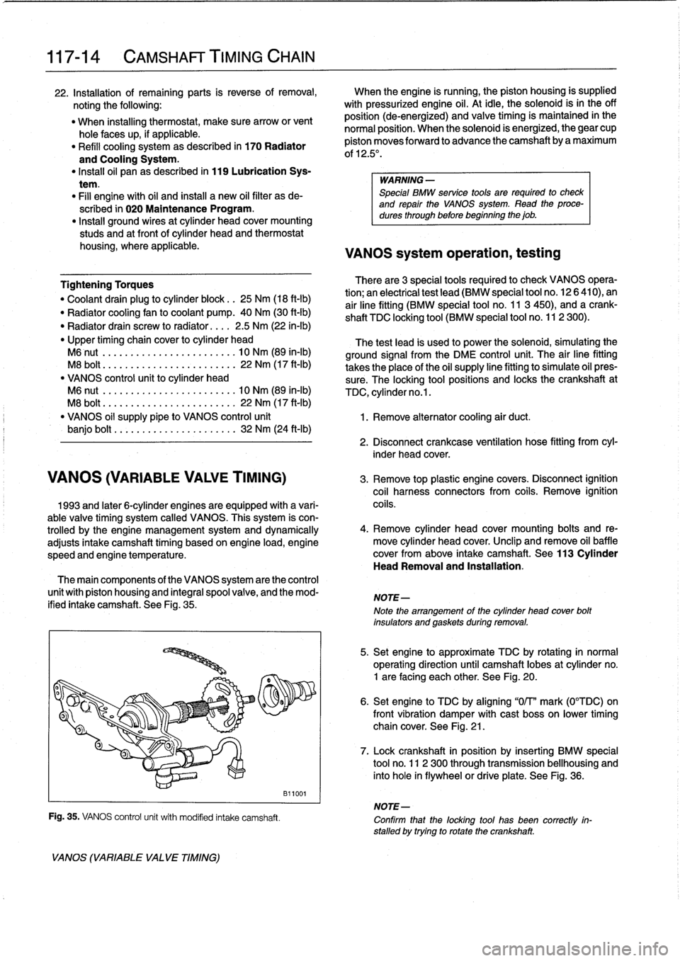
components
of
the
VANOS
system
are
the
control
unit
with
piston
housing
and
integral
spool
valve,
and
the
mod-
ified
intake
camshaft
.
See
Fig
.
35
.
VANOS
(VARIABLE
VA
LVE
TIMING)
Fig
.
35
.
VANOS
control
unit
with
modified
intake
camshaft
.
B11001
WARNING
-
Special
BMW
service
tools
are
required
to
check
and
repair
the
VANOS
System
.
Read
theproce-
dures
through
before
beginning
the
job
.
2
.
Disconnect
crankcase
ventilation
hose
fitting
from
cyl-
inder
head
cover
.
NOTE-
Note
the
arrangement
of
the
cylinder
head
cover
bolt
insulators
and
gaskets
during
removal
.
5
.
Set
engine
to
approximate
TDC
by
rotating
in
normal
operating
direction
until
camshaft
lobes
at
cylinder
no
.
1
are
facing
each
other
.
See
Fig
.
20
.
6
.
Set
engine
to
TDC
by
aligning
"0/T"
mark
(0°TDC)on
front
vibration
damper
withcast
boss
on
lower
timing
chain
cover
.
See
Fig
.
21
.
7
.
Lock
crankshaft
in
position
by
inserting
BMW
special
tool
no
.
11
2
300
through
transmission
bellhousing
and
into
hole
in
flywheelor
driveplate
.
See
Fig
.
36
.
NOTE-
Confirm
that
the
locking
tool
has
been
correctly
in-
stalled
by
trying
to
rotatethe
crankshaft
.