ignition relay BMW 323i 1998 E36 Owner's Guide
[x] Cancel search | Manufacturer: BMW, Model Year: 1998, Model line: 323i, Model: BMW 323i 1998 E36Pages: 759
Page 185 of 759
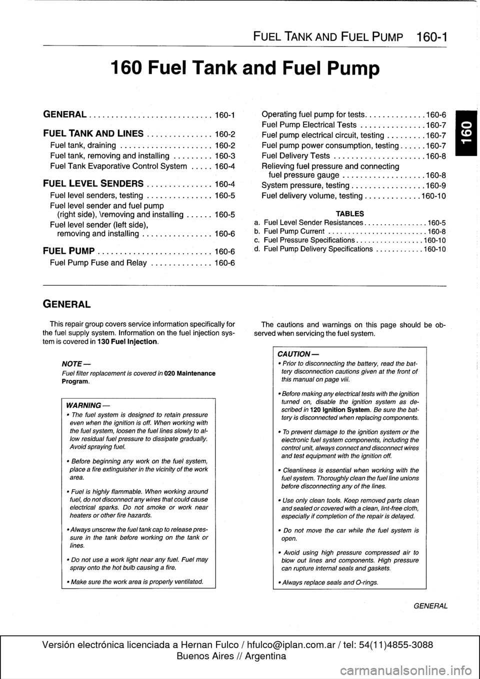
160
Fuel
Tank
and
Fuel
Pump
GENERAL
.
.
.
.
.
.
...........
.
....
.
.
.
.
.
.
160-1
Operating
fuel
pump
for
tests
.
.
.
.
.
.
.......
.160-6
Fuel
Pump
Electrical
Tests
.
.
.
.
.
.
.
...
.
.
.
.
.
160-7
FUEL
TANK
AND
LINES
..
.
.
.
..........
160-2
Fuel
pump
electrical
circuit,
testing.
...
.
.
.
.
.
160-7
Fuel
tank,
draining
..
.
.
.
.
.
.
.
.
.
..........
160-2
Fuel
pump
power
consumption,
testing
.
.
.
.
.
.
160-7
Fuel
tank,
removing
and
installing
.........
160-3
Fuel
Delivery
Tests
....
.
.
.
...
.
.....
.
.
.
..
160-8
Fuel
Tank
Evaporative
Control
System
.....
160-4
Relieving
fuel
pressure
and
connecting
fuel
pressure
gauge
..
.
...........
.
.
.
..
160-8
FUEL
LEVEL
SENDERS
.
.
.
.
.
.......
.
.
.
160-4
System
pressure,
testing
.................
160-9
Fuel
level
senders,
testing
.
.
.
.
.
.......
.
.
.
160-5
Fuel
delivery
volume,
testing
.............
160-10
Fuel
leve¡
sender
and
fuel
pump
(right
side),
emoving
and
installing
.
.
.
.
.
.
160-5
TABLES
Fuel
leve¡
sender
(left
side),
a
.
FuelLeve¡
Sender
Resistances
...........
.
.
..
.160-5
removing
and
installing
.........
.
.
.
.
.
.
.
160-6
b
.
Fuel
Pump
Current
...
.................
..
...
160-8
c
.
Fuel
Pressure
Specifications
..............
.
..
160-10
FUEL
PUMP
.
.
.
................
.
.
.
.
.
.
.
160-6
d
.
Fuel
Pump
Delivery
Specifications
.........
.
..
160-10
Fuel
Pump
Fuse
and
Relay
.
.
.
....
.
.
.
.
.
.
.
160-6
GENERAL
This
repair
group
covers
service
information
specifically
for
The
cautions
and
warnings
on
this
page
should
beob
the
fuel
supply
system
.
Information
on
the
fue¡
injection
sys-
served
when
servicing
the
fuel
system
.
tem
is
covered
in
130
Fuel
Injection
.
NOTE-
Fue¡
filter
replacement
is
covered
in
020
Maintenance
Program
.
WARNING
-
"
The
fuel
system
is
designed
to
retain
pressure
even
when
the
ignition
isoff
.
When
working
with
the
fuel
system,
loosen
the
fuel
lines
slowly
toal-
low
residual
fuel
pressure
to
dissipate
gradually
.
Avoid
spraying
fuel
.
"
Before
beginning
any
work
on
the
fuel
system,
place
a
tire
extinguisher
in
the
vicinity
of
the
work
area
.
"
Fuel
is
highly
flammable
.
When
working
around
fuel,
do
not
disconnect
any
wires
that
could
cause
electrical
sparks
.
Do
not
smoke
or
work
near
heaters
or
other
tire
hazards
.
"
Always
unscrew
the
fuel
tank
cap
to
release
pres-
sure
in
the
tank
before
working
on
the
tank
or
fines
.
"
Do
not
use
a
work
light
near
any
fuel
.
Fuel
may
spray
onto
the
hot
bulb
causing
a
tire
.
"
Make
sure
the
work
area
is
properly
ventifated
.
FUEL
TANK
AND
FUEL
PUMP
160-1
CAUTION-
"
Prior
to
disconnecting
the
battery,
read
the
bat-tery
disconnection
cautions
given
at
the
front
of
this
manual
onpage
viü
.
"
Before
making
any
electrical
tests
with
the
ignition
tumed
on,
disable
the
ignition
system
as
de-
scribed
in
120
Ignition
System
.
Be
sure
the
bat-tery
is
disconnected
when
replacing
components
.
"
To
prevent
damage
to
the
ignition
system
or
the
electronic
fuel
system
components,
including
the
control
unit,
aiways
connect
and
disconnect
wires
and
test
equipment
with
the
ignition
off
.
"
Cleanliness
is
essential
when
working
with
the
fuel
system
.
Thoroughly
clean
the
fuel
fine
unionsbefore
disconnecting
any
of
the
fines
.
"
Use
only
clean
tools
.
Keep
removed
parts
clean
and
sealed
or
covered
with
a
clean,
lint-free
cloth,
especially
if
completion
of
the
repair
is
delayed
.
"
Do
not
move
the
car
while
the
fuel
system
is
open
.
"
Avoid
using
high
pressure
compressed
air
to
blow
out
fines
and
componente
.
High
pressure
can
rupture
infernal
seals
and
gaskets
.
"
Always
replace
seals
and
O-rings
.
GENERAL
Page 190 of 759
160-
6
FUEL
TANK
AND
FUEL
PUMP
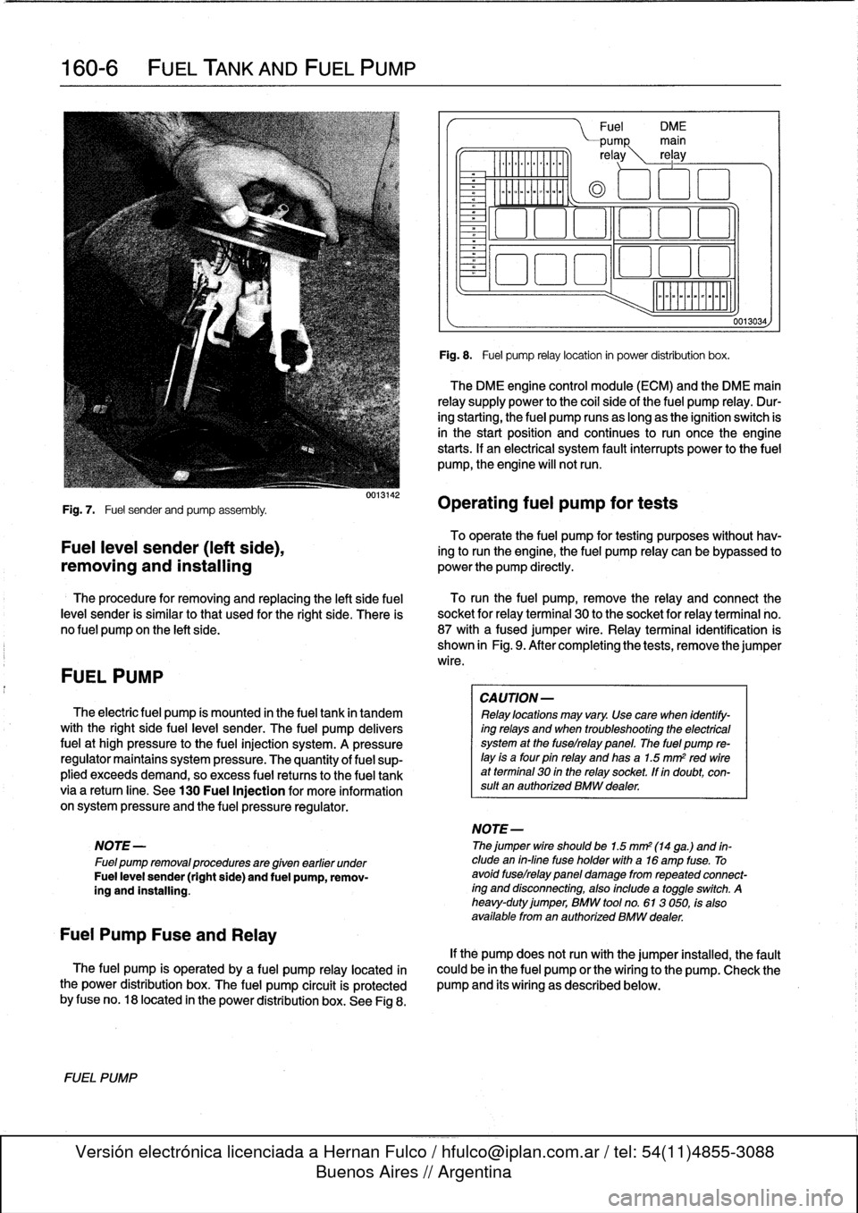
Fig
.
7
.
Fuel
sender
and
pump
assembly
.
To
operate
the
fuel
pump
for
testing
purposes
without
hav-
Fuel
leve¡
sender
(left
side),
ing
to
runthe
engine,
the
fuel
pump
relay
can
be
bypassed
to
removing
and
installing
powerthe
pump
directly
.
The
procedure
for
removing
and
replacing
the
left
side
fuel
To
runthe
fuel
pump,
remove
the
relay
and
connect
the
leve¡
sender
is
similar
tothat
used
for
the
right
side
.
There
is
socket
for
relayterminal
30
to
the
socket
for
relay
terminal
no
.
no
fuel
pump
on
the
left
side
.
87
with
afused
jumper
wire
.
Relay
terminal
identification
is
shown
in
Fig
.
9
.
After
completing
the
tests,
remove
the
jumper
wire
.
FUEL
PUMP
The
electric
fuel
pump
ís
mounted
in
the
fuel
tank
in
tandem
with
the
right
side
fuelleve¡
sender
.
The
fuel
pump
delivers
fuel
at
high
pressure
to
the
fuel
injection
system
.
A
pressure
regulator
maintains
system
pressure
.
The
quantity
of
fuel
sup-
plied
exceeds
demand,
so
excess
fuel
retums
to
the
fuel
tank
via
a
retum
líne
.
See
130
Fuel
Injection
for
more
information
on
system
pressure
and
the
fuel
pressure
regulator
.
NOTE
-
Fuel
pump
removalprocedures
are
given
earlier
under
Fuel
leve¡
sender
(right
side)
and
fuel
pump,
remov-
íng
and
installing
.
Fuel
Pump
Fuse
and
Relay
The
fuel
pump
is
operated
by
a
fuel
pump
relay
located
ín
the
power
distribution
box
.
The
fuel
pump
circuit
is
protected
by
fuse
no
.
18
located
in
the
power
distribution
box
.
See
Fig
8
.
FUEL
PUMP
0013142
Fuel
DM
E
PUMP
main
re
ay
rel
ay
0
aoo
o
~a
aao
ó
Fig
.
8
.
Fuel
pump
relay
location
in
power
distribution
box
.
The
DME
engine
control
module
(ECM)
and
the
DME
main
relay
supply
power
to
the
coi¡
sideof
the
fuel
pump
relay
.
Dur-
ing
starting,
the
fuel
pump
runs
as
long
as
the
ignition
switch
is
in
the
start
position
and
continues
to
run
oncethe
engine
starts
.
If
an
electrical
system
fault
interrupts
power
to
the
fuel
pump,
the
engine
will
notrun
.
Operating
fuel
pump
for
tests
CA
UTION-
Relay
locations
may
vary
.
Use
care
when
identify-
ing
relays
and
when
troubleshooting
the
electrical
system
at
the
fuselrelay
panel
.
The
fuel
pump
re-
¡ay
is
a
four
pin
relay
and
has
a
1.5
mm
2
red
wireat
terminal
30
in
the
relay
socket,
lf
in
doubt,
con-
sult
an
authorized
BMW
dealer
.
NOTE-
Thejumper
wire
shouldbe
1.5
mm2
(14
ga
.)
and
in-
clude
en
in-fine
fuse
holder
with
a16
amp
fuse
.
To
avoid
fuselrelay
panel
damage
fromrepeated
connect-
íng
and
disconnecting,
also
include
a
toggleswitch
.
A
heavy-duty
jumper,
BMW
tool
no
.
613
050,
fs
also
available
from
en
authorized
BMW
dealer
.
0013034,
If
the
pump
does
notrun
with
the
jumper
installed,
the
fault
could
be
in
the
fuel
pump
or
the
wiring
to
the
pump
.
Check
the
pump
and
its
wiring
as
described
below
.
Page 199 of 759
NOTE-
Some
cars
covered
by
this
manual
may
have
an
alter-
nate
cooling
fan
switchwith
switching
temperatures
of
176%190W
(80%88°C)
.
When
replacing
the
switch
check
theswitching
specifications,
whichshouldbe
stamped
on
the
switch
body
.
1
.
If
coolant
is
circulating
at
normal
operating
tempera-
ture,
but
auxiliary
cooling
fan
does
not
run,
disconnect
connector
from
radiator
temperature
switch
and
make
tests
listed
in
Table
c
.
Table
c
.
Auxiliary
Cooling
Fan
Temperature
Switch
Tests
Wires
jumpered
Test
Test
resuits
conditions
Black/green
(terminal2)
and
Ignition
ON
Fan
runs
on
brown
(terminal
1)
low
speed
Black/gray
(terminal
3)
and
Ignition
ON
Fan
runson
brown
(terminal
I
1)
high
speed
2
.
If
fan
runs
only
when
powered
directly
by
jumpered
connector
and
hot
coolant
is
circulating
through
radia-
tor,
radiator
temperature
switch
is
most
likelyfaulty
.
Use
a
new
sealing
ring
when
replacing
switch
Tightening
Torque
"
Temperature
switch
to
radiator
......
15
Nm
(11
ft-Ib)
3
.
If
auxiliary
fan
does
notrun
when
powered
directly,
check
for
battery
voltage
at
temperature
switch
connec-
tor
(black/green
wire)
with
ignition
on
.
If
battery
voltage
is
not
present,
check
fuses
.
See
610
Electrical
Com-
ponent
Locations
.
RADIATOR
AND
COOLING
SYSTEM
170-
5
~r~nmm
a
00
0
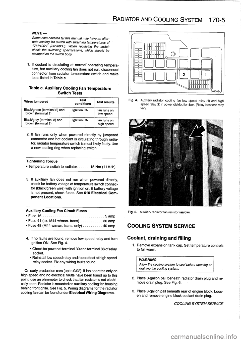
Fig
.
4
.
Auxiliary
radiator
cooling
fan
low
speed
relay
(1)
and
high
speed
relay
(2)
in
power
distribution
box
.
(Relay
locations
may
vary
.)
Auxiliary
Cooling
Fan
Circuit
Fuses
Fig
.
5
.
Auxiliary
radiator
fan
resistor
(arrow)
.
"
Fuse16
.
...................
..
..
...
...
.5
amp
"
Fuse
41
(ex
.
M44
w/man
.
trans)
.
..
.
..
.....
30
amp
"
Fuse
48
(M44
w/man
.
trans
.
only)
..
.
..
.....
40
amp
COOLING
SYSTEM
SERVICE
0013034
4
.
If
no
faults
are
found,
remove
low
speed
relay
and
turn
Coolant,draining
and
filling
ignition
ON
.
See
Fig
.
4
.
1
.
Remove
expansion
tank
cap
.
Set
temperature
controls
"
Check
for
power
at
terminal
30
and
terminal
86
of
relay
to
full
warm
.
socket
.
"
Reinstall
low
speed
relay
and
repeat
testat
high
speed
WARNING
-
relay
socket
.
Fix
any
wiring
faults
found
.
Allow
the
cooling
system
to
cool
before
openlng
or
On
early
productioncars
(up
to
9/92)
:
If
fan
operates
only
on
draining
the
cooling
system
.
high
speed
and
no
electrical
faults
have
been
foundup
to
this
point,
usean
ohmmeter
to
check
that
fan
resistor
is
not
electri-
2
.
Place
3
ra
allo
ug
.
beneath
radiator
drain
plug
and
re-
cally
open
.
Resistor
is
mounted
on
auxiliary
cooling
fan
housing
move
drain
plg
.
See
Fig
.
6
.
behind
front
grille
.
See
Fig
.
5
.
Wiring
diagrams
for
the
radiator
cooling
fan
canbefoundunder
Electrical
Wiring
Diagrams
.
3
.
Place
3-g
pail
beneath
rear
of
engine
blo
.
Loos-
en
and
re
mlon
ove
engine
blockcoolant
drain
plug
k
.
COOLING
SYSTEM
SERVICE
Page 307 of 759
Ambient
temperaturelclock
MÍM
Aa
.Mi}rm
-Mil"
IMua~naa~u~itacar
"
za
.~
Central
Body
Electronics
0013028
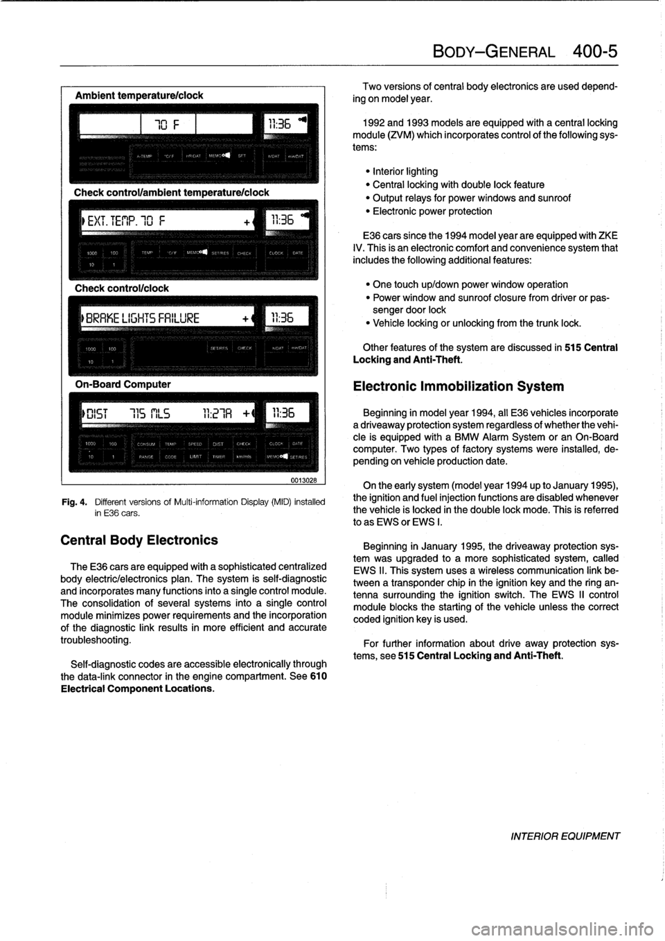
Fig
.
4
.
Different
versionsof
Multi-information
Display(MID)
installed
in
E36
cars
.
The
E36
cars
are
equipped
with
a
sophisticated
centralized
body
electric/electronics
plan
.
The
system
is
self-diagnostic
and
incorporates
many
functions
into
a
single
control
module
.
The
consolidation
of
several
systems
into
a
single
control
module
minimizes
power
requirements
and
the
incorporation
of
the
diagnostic
link
results
in
more
efficient
and
accurate
troubleshooting
.
Self-diagnostic
codes
are
accessible
electronically
through
the
data-link
connector
in
the
engine
compartment
.
See610
Electrical
Component
Locations
.
BODY-GENERAL
400-
5
Two
versions
of
central
body
electronics
are
used
depend-
ing
on
model
year
.
1992
and
1993
models
are
equipped
with
a
central
locking
module
(ZVM)
which
incorporates
control
of
the
following
sys-
tems
:
"Interiorlighting
"
Central
locking
with
double
lock
feature
"
Output
relays
for
powerwindows
and
sunroof
"
Electronic
power
protection
E36
cars
since
the
1994
model
year
are
equipped
with
ZKE
IV
.
This
is
an
electronic
comfort
and
convenience
system
that
includes
the
following
additional
features
:
"
One
touch
up/down
power
window
operation
"
Power
window
and
sunroof
closure
from
driver
or
pas-
sengerdoor
lock
"
Vehicle
locking
or
unlocking
from
the
trunk
lock
.
Other
features
of
the
system
are
discussed
in
515
Central
Locking
and
Anti-Theft
.
Electronic
Immobilization
System
Beginning
in
model
year
1994,
all
E36
vehicles
incorporate
adriveaway
protection
system
regardless
of
whether
the
vehi-
cle
is
equipped
with
a
BMW
Alarm
System
or
an
On-Board
computer
.
Two
types
of
factory
systems
were
installed,
de-
pending
on
vehicle
production
date
.
On
the
early
system
(model
year
1994
up
to
January
1995),
the
ignition
and
fuel
injection
functions
are
disabled
whenever
the
vehicle
is
locked
in
the
double
lock
mode
.
This
is
referred
lo
as
EWS
or
EWS
I
.
Beginning
in
January
1995,
the
driveaway
protection
sys-
tem
was
upgraded
to
a
more
sophisticated
system,
called
EWS
II
.
This
system
uses
a
wireless
communication
link
be-
tween
a
transponder
chip
in
the
ignition
keyand
the
ring
an-
tenna
surrounding
the
ignition
switch
.
The
EWS
II
control
module
blocksthe
starting
of
the
vehicle
unlessthe
correct
coded
ignition
key
is
used
.
For
further
information
about
drive
away
protection
sys-
tems,
see
515
Central
Locking
and
Anti-Theft
.
INTERIOR
EQUIPMENT
Page 381 of 759
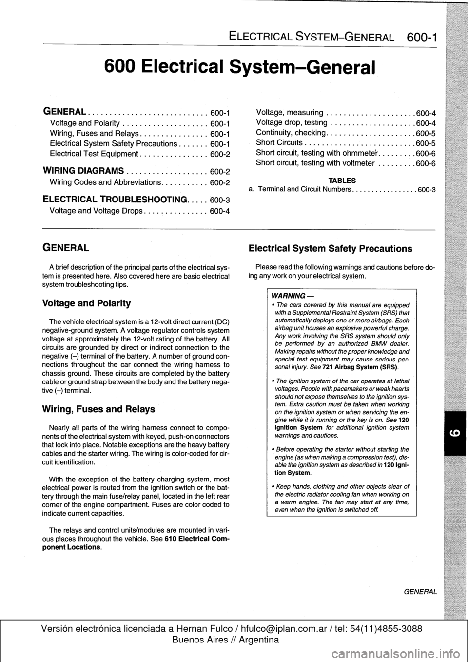
600
Electrical
System-General
GENERAL
.
...........
.
.
.
.
.
.
.
.
.
...
.
...
600-1
Voltage
and
Polarity
........
.
.
.
.
.
.
.
.....
600-1
Ming,
Fuses
and
Relays
............
.
.
.
.
600-1
Electrical
System
Safety
Precautions
...
.
.
.
.
600-1
Electrical
Test
Equipment
.....
.
.
.
....
.
.
.
.
600-2
WIRING
DIAGRAMS
..
.
.
.
.
.
.
.
.
.
........
600-2
Ming
Codes
and
Abbreviations
..
.
...
.
....
600-2
ELECTRICAL
TROUBLESHOOTING
..
.
..
600-3
Voltage
and
Voltage
Drops
..........
.
.
.
.
.
600-4
GENERAL
Electrical
System
Safety
Precautions
A
brief
description
of
the
principal
parts
of
the
electrical
sys-
tem
is
presented
here
.
Also
covered
here
are
basic
electrical
system
troubleshooting
tips
.
Voltage
and
Polarity
The
vehicle
electrical
system
is
a
12-volt
direct
current
(DC)
negative-ground
system
.
A
voltage
regulator
controls
system
voltage
at
approximately
the
12-volt
rating
of
the
battery
.
Al¡
circuits
are
grounded
by
direct
or
indirect
connection
to
the
negative
(-)
terminal
of
the
battery
.
A
number
of
ground
con-
nections
throughout
the
car
connect
the
wiring
harness
to
chassis
ground
.
These
circuits
are
completedby
the
battery
cable
or
ground
strap
between
the
body
and
the
battery
nega-
tive
(-)
terminal
.
Wiring,
Fuses
and
Relays
Nearly
all
parts
of
the
wiring
harnessconnect
to
compo-
nents
of
the
electrical
system
with
keyed,
push-on
connectors
that
lock
into
place
.
Notable
exceptions
arethe
heavy
battery
cables
and
the
starter
wiring
.
The
wiring
is
color-coded
for
cir-
cuitidentification
.
With
theexception
of
the
battery
charging
system,
most
electrical
power
is
routed
from
the
ignition
switch
or
the
bat-
tery
through
the
main
fuse/relay
panel,
located
in
¡he
left
rear
comer
of
the
engine
compartment
.
Fuses
are
color
coded
to
indicate
current
capacities
.
The
relays
and
control
units/modules
are
mounted
in
vari-
ous
places
throughout
the
vehicle
.
See610
Electrical
Com-
ponent
Locations
.
ELECTRICAL
SYSTEM-GENERAL
600-1
Voltage,
measuring
.
.
.
................
.
.
600-4
Voltage
drop,
testing
.
.
.....
.
.....
.
......
600-4
Continuity,
checking
..
.
...
.
.
.
.
.
.
.
.
.
.
.
.
.
.
.
600-5
Short
Circuits
.
.
.
.
.
.
.
.
.....
.
...
.
.
.
.
.
.
.
.
.
600-5
Short
circuit,
testing
with
ohmmete'r
.
.
.
.
.
.
.
.
.
600-6
Short
circuit,
testing
with
voitmeter
.
.
.
.
.
.
.
.
.
600-6
TABLES
a
.
Terminal
and
Circuit
Numbers
..............
..
.600-3
Please
read
the
following
warnings
and
cautions
before
do-
ing
any
work
on
your
electrical
system
.
WARNING
-
"
The
cars
covered
by
this
manual
are
equipped
with
aSupplemental
Restraint
System
(SRS)
that
automatically
deploys
one
or
more
airbags
.
Each
airbag
unit
houses
an
explosive
powerful
charge
.
Any
work
involving
the
SRS
system
should
only
be
performed
byan
authorized
BMW
dealer
.
Making
repairs
without
the
proper
knowledge
and
special
test
equipment
may
cause
serious
per-
sonal
injury
.
See
721
Airbag
System
(SRS)
.
"
The
ignition
system
of
the
car
operates
at
lethal
voltages
.
People
with
pacemakers
or
weak
hearts
should
not
expose
themselves
to
the
ignition
sys-
tem
.
Extra
caution
mustbe
taken
when
working
on
the
ignition
system
or
when
servicing
theen-
gine
while
it
is
runningor
the
key
is
on
.
See
120
Ignition
System
for
additional
ignition
system
warnings
and
cautions
.
"
Before
operating
the
starter
without
starting
the
engine
(as
when
making
a
compressfon
test),
dis-
able
the
ignition
system
as
described
in
120
Igni-
tion
System
.
"
Keep
hands,
clothing
and
other
objects
clear
of
the
electric
radiator
coollng
fan
when
working
on
a
warm
engine
.
The
fan
may
start
at
any
tíme,
even
when
the
ignition
is
switched
off
.
GENERAL
Page 382 of 759
600-2
ELECTRICAL
SYSTEM-GENERAL
CAUTION
-
"
Always
turn
off
the
engine
and
disconnect
the
negative
()
cable
from
the
batterybefore
remov-
ing
any
electrical
components
.
Disconnecting
the
battery
may
erase
fault
code(s)
stored
in
control
module
memory
.
Check
for
fault
codes
using
spe-
cial
BMW
diagnostic
equipment
.
"
Prior
to
disconnecting
the
battery,
read
the
bat-
tery
disconnection
cautions
given
at
the
front
of
this
manual
onpage
viii
.
"
Connect
and
disconnect
ignition
system
wires,
multiple
connectors,
and
ignition
test
equipment
leads
only
while
the
ignition
is
off
.
"
Do
not
disconnect
the
battery
with
engine
run-
ning
.
"
Do
not
quick-charge
the
battery
(for
boost
start-
ing)
for
longer
than
one
minute,
and
do
not
ex-
ceed
16
.5
volts
at
the
battery
with
the
boosting
cables
attached
.
Wait
at
feast
one
minute
before
boosting
the
battery
a
second
time
.
"
Do
not
usea
test
famp
that
has
a
normal
incan-
descent
bulb
to
test
circuits
contafning
electronic
components
.
The
high
electrical
consumptionof
these
test
lamps
may
damage
the
components
.
"
Do
not
use
an
analog
meter
.
Use
onfy
a
digital
multimeter
.
"
Many
of
the
solid-state
modules
are
static
sensi-
tive
.
Static
discharge
will
permanently
damage
them
.
Always
handle
the
modules
using
proper
static
prevention
equipment
and
techniques
.
"
To
avoid
damaging
harness
connectors
or
relay
panel
sockets,
use
jumper
wires
with
flat-blade
connectors
that
are
the
same
size
as
the
connec-
tor
or
relay
terminals
.
"
Always
switch
a
digital
multimeter
to
the
appropri-
ate
function
and
range
before
making
test
con-
nections
.
"
Do
not
tryto
start
the
engine
of
a
carwhich
has
been
heated
above176°F
(80°C),
(for
example,
in
a
paint
dryingbooth)
.
Allow
it
to
cool
to
normal
temperature
.
"
Disconnect
the
battery
before
dolng
any
electric
welding
on
the
car
.
"
Do
not
wash
the
engine
while
it
is
runnfng,
or
any-
time
the
ignition
is
switched
on
.
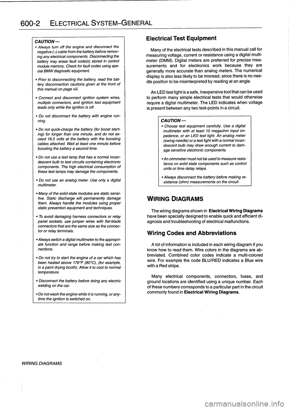
WIRING
DIAGRAMS
Electrical
Test
Equipment
Many
of
the
electrical
tests
described
in
this
manual
call
for
measuring
voltage,
currentorresistanceusing
a
digital
multi-
meter
(DMM)
.
Digital
meters
are
preferred
for
precise
mea-
surements
and
for
electronics
work
because
they
are
generally
more
accuratethan
analog
meters
.
The
numerical
display
is
alsoless
likely
to
be
misread,
since
there
is
no
nee-
dle
position
to
be
misinterpreted
by
reading
at
an
angle
.
An
LED
test
light
is
a
safe,
inexpensive
tool
that
can
be
used
to
perform
many
simple
electrical
tests
that
would
otherwise
require
a
digital
multimeter
.
The
LED
indicates
when
voltage
is
present
between
anytwo
test-points
in
a
circuit
.
CA
UTION-
"
Choose
test
equipment
carefully
.
Use
a
digital
multimeter
with
at
leadt
10
megaohm
input
im-
pedance,or
an
LED
test
light
.
An
analog
meter
(swing-need1e)
ora
test
light
with
a
normal
incan-
descent
bulb
may
draw
enough
current
to
dam-
age
sensitive
electronic
components
.
"
An
ohmmeter
must
not
beused
to
measure
resis-
tance
on
solidstate
components
suchas
controlunits
or
time
delay
relays
.
"
Always
disconnect
the
battery
before
making
re-
sístance
(ohm)
measurements
on
the
circuit
.
WIRING
DIAGRAMS
The
wiring
diagrams
shown
in
Electrical
Wiring
Diagrams
have
been
specially
designed
to
enable
quick
and
efficientdi-
agnosis
and
troubleshooting
of
electrical
malfunctions
.
Wiring
Codes
and
Abbreviations
A
lot
of
information
is
included
in
each
wiring
diagram
if
you
know
how
to
read
them
.
Wire
colors
in
the
diagrams
are
ab-
breviated
.
Combined
color
codes
indicate
a
multi-colored
wire
.
For
example
the
code
BLU/RED
indicates
a
Blue
wire
with
a
Red
stripe
.
Many
electrical
components,
connectors,
fuses,
and
ground
locations
are
identified
using
a
unique
number
.
Each
of
there
numbers
corresponds
to
a
particular
part
in
the
circuit
commonly
found
in
Electrical
Wiring
Diagrams
.
Page 383 of 759
NOTE
-
Sometimes
the
color
of
en
installed
wire
may
be
differ-
ent
than
the
one
on
the
wiring
diagram
.
Don't
be
con-
cerned
.
Just
be
sure
lo
confirm
that
the
wire
connects
lo
the
proper
terminals
.
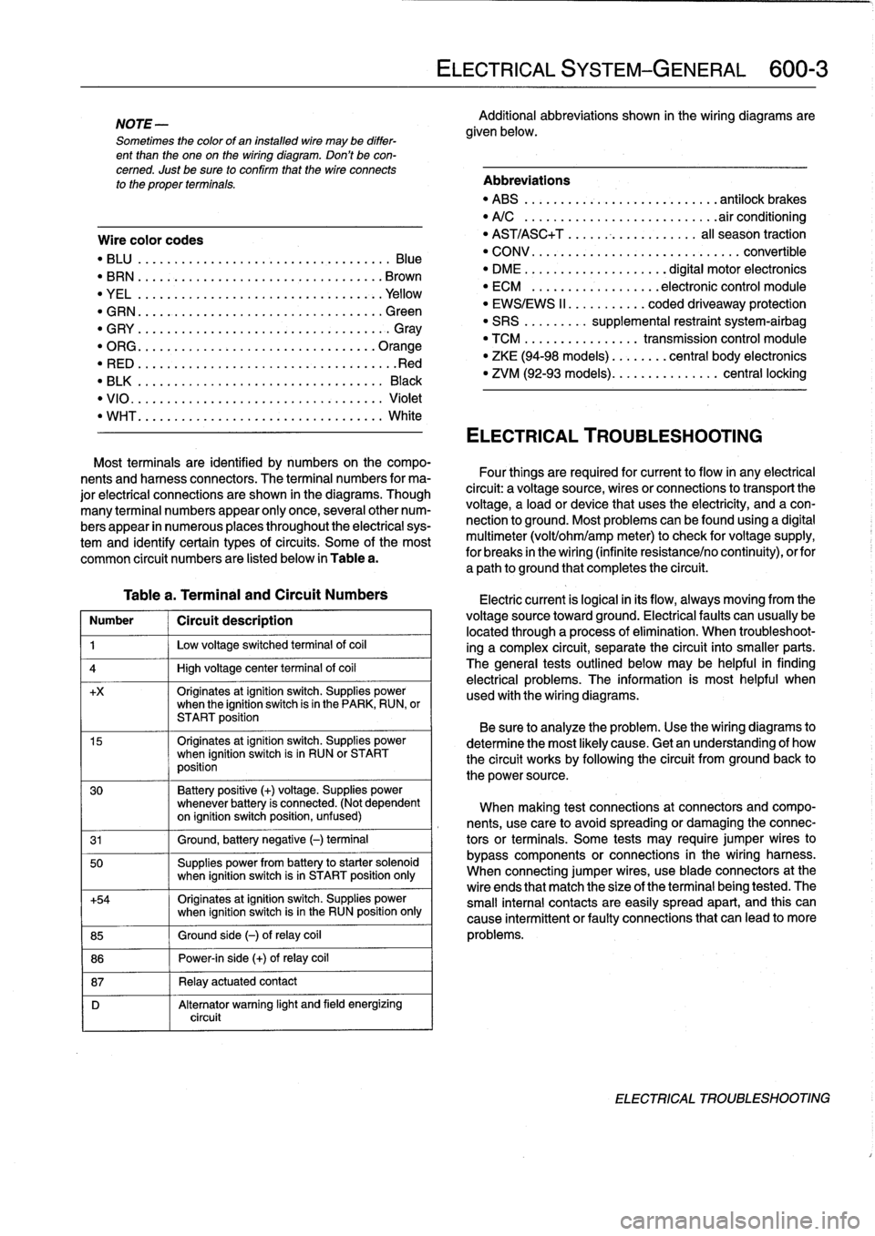
Wire
color
codes
"
BLU
.........
.
..
..
...
.
.................
Blue
"
BRN
....:....
.
..
..
...
..
...............
Brown
"
YEL
.........
.
..
..
...................
.Yellow
"
GRN
.........
.
..
..
...
.
................
creen
"
G
RY
.......
.
.
.
..
..
.....................
G
ray
"
ORG
.........
.
..
..
...
.
..............
.Orange
"
RED
......
...
.
.
..
.....................
.Red
"
BLK
.........
.
..
..
...
.
................
Black
"
VIO
..........
.
..
...
..
..
.......
.
.......
Violet
"
WHT
.........
.
.
....
.
...
:..............
White
Table
a
.
Terminal
and
Circuit
Numbers
Number
1
Circuít
description
1
j
Low
voltage
switched
terminal
of
coi¡
4
1
High
voltage
center
termina¡
of
coi¡
+x
Originates
atignition
switch
.
Supplies
powerwhen
the
ignition
switch
is
in
the
PARK,
RUN,
or
START
position
15
Originates
atignition
switch
.
Supplies
powerwhen
ignition
switch
is
in
RUN
or
START
position
30
Battery
positive
(+)
voltage
.
Supplies
power
whenever
battery
is
connected
.
(Not
dependent
on
ignition
switch
position,
unfused)
31
1
Ground,
battery
negative
(-)
terminal
50
Supplies
power
from
battery
to
starter
solenoid
when
ignition
switch
isin
START
position
only
+54
Originates
atignition
switch
.
Supplies
power
when
ignition
switch
isin
the
RUN
position
only
85
1
Ground
side
(-)
ofrelay
coil
86
1
Power-in
side
(+)
ofrelay
coil
87
1
Relay
actuatedcontact
D
Alternator
warning
light
and
field
energizing
circuit
ELECTRICAL
SYSTEM-GENERAL
600-
3
Additional
abbreviations
shown
in
the
wiring
diagrams
are
given
below
.
Abbreviations
"
ABS
........
.
...
.
...
.
..........
antilock
brakes
"
A/C
........
.
...
..
..
.
.........
.airconditioning
"
AST/ASC+T
.......
...
.
.
.......
al¡
season
traction
"
CONV
.......
.
.
...
.................
convertible
"
DME
........
.
.
...
.......
digital
motor
electronics
"
ECM
.......
.
...
..
..
.
..
electronic
control
module
"
EWS/EWS
II
......
...
.
.
coded
driveaway
protection
"
SRS
........
.
supplemental
restraint
system-airbag
"
TCM
........
.
..
....
.
transmission
control
module
"
ZKE
(94-98
models)
..
..
.
...
central
body
electronics
"
ZVM
(92-93
models)
...
.
.
..
.
.......
central
locking
ELECTRICAL
TROUBLESHOOTING
Most
terminals
are
identified
by
numbers
on
the
compo-
nents
and
harness
connectors
.
The
terminal
numbers
for
ma-
Four
things
are
required
for
current
toflow
in
any
electrical
jor
electrical
connections
are
shown
in
the
diagrams
.
Though
circuit
:
a
voltagesource,
wires
or
connections
to
transport
the
many
terminal
numbers
appear
only
once,
severa¡other
num-
voltage,
a
load
or
device
that
uses
the
electricity,
and
a
con-
bers
appear
in
numerous
places
throughout
the
electrical
sys-
nection
to
ground
.
Most
problemscanbefound
using
a
digital
tem
and
identify
certain
types
ofcircuits
.
Some
of
the
most
multimeter
(volt/ohm/amp
meter)to
check
for
voltage
supply,
common
circuit
numbers
are
listed
below
in
Table
a
.
for
breaks
in
the
wiring
(infinite
resistance/no
continuity),
orfor
a
path
to
ground
that
completesthe
circuit
.
Electric
current
is
logical
in
its
flow,
always
moving
from
the
voltage
sourcetoward
ground
.
Electricalfaults
can
usually
be
located
through
a
process
of
elimination
.
When
troubleshoot-
ing
a
complex
circuit,
separate
the
circuit
into
smaller
parts
.
The
general
testsoutlined
below
may
be
helpful
in
finding
electrical
problems
.
The
information
is
most
helpful
when
used
with
the
wiring
diagrams
.
Be
sure
to
analyze
the
problem
.
Use
the
wiring
diagrams
to
determine
the
most
likely
cause
.
Getan
understanding
of
how
the
circuit
works
by
following
the
circuit
from
groundback
to
the
power
source
.
When
making
test
connections
at
connectors
andcompo-
nents,
use
care
to
avoidspreading
or
damaging
the
connec-
tors
or
terminals
.
Some
tests
may
require
jumper
wires
to
bypass
components
or
connections
in
the
wiring
harness
.
When
connecting
jumper
wires,
use
bladeconnectors
at
the
wire
ends
that
match
the
size
of
the
terminal
being
tested
.
The
small
interna¡
contacts
are
easily
spread
apart,
and
this
can
cause
intermittent
or
faultyconnections
that
can
leadto
more
problems
.
ELECTRICAL
TROUBLESHOOTING
Page 385 of 759
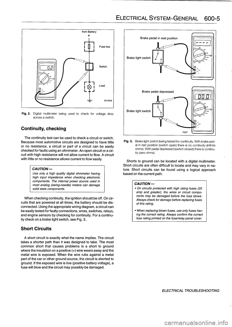
Continuity,
checking
Short
Circuits
from
Battery
CAUTION-
Use
only
a
high
quality
digital
ohmmeter
having
high
input
impedance
when
checking
electronic
componente
.
The
internal
power
source
used
in
most
analog
(swing-need1e)
meterscan
damage
solidstate
components
.
0013239
Fig
.
2
.
Digital
multimeter
being
used
to
check
for
voltage
drop
across
a
switch
.
The
continuity
test
can
beused
to
check
a
circuit
or
switch
.
Because
most
automotive
circuits
are
designed
to
have
little
or
no
resistance,
a
circuit
or
part
of
a
circuit
canbe
easily
checked
for
faults
using
an
ohmmeter
.
An
open
circuit
or
a
cir-
cuit
withhigh
resistance
will
not
allow
current
to
flow
.
A
círcuit
with
little
or
no
resistanceallows
current
to
flow
easily
.
When
checking
continuity,
the
ignition
should
be
off
.
On
cir-
cuits
that
are
powered
at
all
times,
the
battery
should
be
dis-
connected
.
Using
the
appropriate
wiring
diagram,
a
circuit
can
be
easily
tested
for
faulty
connections,
wires,
switches,
relays,
and
engine
sensorsby
checking
forcontinuity
.
For
a
continu-
ity
check
on
a
brake
light
switch,
see
Fig
.
3
..
A
short
circuit
is
exactly
what
the
narre
implies
.
The
circuit
takes
a
shorter
paththan
it
was
designed
to
take
.
The
most
common
short
that
causes
problems
is
a
short
to
ground
where
the
insulation
on
a
positive
(+)
wire
wears
away
and
the
metal
wire
is
exposed
.
When
the
wire
rubs
against
a
metal
partof
thecar
or
other
ground
source,
the
circuit
is
shorted
to
ground
.
If
the
exposed
wire
is
live
(positive
battery
voltage),
a
Puse
will
blow
and
the
circuit
may
possibly
be
damaged
.
ELECTRICAL
SYSTEM
-
GENERAL
600-
5
Brake
light
switch
Brake
pedal
in
rest
position
Q
Brake
pedal
depressed
Brake
light
switch
Fig
.
3
.
Brake
light
switchbeing
tested
for
continuity
.
With
brake
ped-
alin
rest
position
(switch
open)
there
is
no
continuity
(infinite
ohms)
.
With
pedal
depressed
(switch
closed)
there
is
continu-
ity
(zero
ohms)
.
Shorts
to
groundcanbe
located
with
a
digital
multimeter
.
Short
circuits
are
often
difficult
to
locate
and
may
vary
in
na-
ture
.
Short
circuits
can
befound
using
a
logical
approach
based
onthe
current
path
.
CAUTION
-
"
On
circuits
protected
with
high
rating
fuses
(25
amp
and
greater),
the
wires
or
circuit
compo-
nents
may
be
damaged
before
the
fuse
blows
.
Always
check
for
damage
before
replacing
fuses
of
this
rating
.
"
When
replacing
blown
fuses,
use
only
fuses
hav-
ingthe
correct
rating
.
Always
confirm
the
correct
fuse
rating
printed
on
the
fuselrelay
panelcover
DC
ELECTRICAL
TROUBLESHOOTING
Page 387 of 759
610
Electrical
Component
Locations
GENERAL
...........
.
.
.
.
.
.
.
.
.
........
610-1
FOSE
POSITION
TABLES
..
.
.
.
.
.
.....
.
610-19
FUSE
AND
RELAY
POSITIONS
.
...
.
.
.
.
.
610-1
Fuse
Positions
.
.
.
................
.
.
.
.
.
610-1
Relay
Positions
.
.
.
.....
.
.
.
........
.
.
.
.
.
610-2
Auxiliary
RelayPanel
.....
.
...
.
........
.
610-2
SplicePanel,
Left
.
.
.
...
.
.
.
...
.
........
.
610-2
SplicePanel,
Right
.
.
.
.
.
.
.
.
...
.
.........
610-3
COMPONENT
LOCATIONS
.
.
.
.
.......
.
.610-3
Component
Location
Table
.
.
.
.
.
.
.........
610-9
GENERAL
FUSE
AND
RELAY
POSITIONS
This
repair
group
covers
f
use,
relay,
and
control
module
lo-
The
front
power
distribution
box,
an
auxiliary
relay
panel,cation
information
.
Electrical
equipment
and
accessories
in-
and
two
auxiliary
splice
panels
contain
most
of
the
fuses
and
stalled
varies
depending
on
model
and
model
year
.
Always
relays
in
E36
vehicles
.
Refer
to
the
component
location
later
confirm
that
the
proper
electrical
component
has
been
identi-
in
this
section,
as
well
as
the
tables
at
the
end
of
this
repair
fied
by
using
the
electrical
wiring
diagrams
.
group
for
electrical
component
location
.
WARNING
-
On
cars
equipped
with
airbags,
special
precautionsapply
to
any
electrical
system
testing
orrepair
.
Air-
bag
units
areexplosive
devices
and
mustbe
han-
dled
with
extremecare
.
Before
starting
any
work
onan
airbag
equipped
car,
refer
to
the
wamings
and
cautions
in
721
Airbag
System
(SRS)
.
CAUTION
-
"
Prior
to
disconnectiog
the
battery,
read
the
bat-
tery
disconnection
cautions
given
at
the
front
of
this
manual
on
page
viii
.
"
Relay
and
fuse
positions
are
subject
to
changeand
may
varyfrom
car
to
car
.
If
questions
arise,
an
authorized
BMW
dealer
is
the
best
source
for
the
most
accurate
and
up-to-date
information
.
"
A
good
way
to
verify
a
relay
position
isto
com-
pare
the
wiring
colors
at
the
relay
socket
to
thecolors
indicated
on
the
wiring
diagrams
located
at
the
rear
of
this
manual
.
"
Always
switchthe
ignition
off
and
disconnect
the
negative
(-)
battery
cable
before
removing
any
electrical
components
.
"
Connect
and
disconnect
ignition
system
wires,
multiple
connectors,
and
ignition
test
equipment
leads
only
while
the
ignition
is
switched
off
.
"
Only
usea
digital
multimeter
for
electrical
tests
.
ELECTRICAL
COMPONENT
LOCATIONS
610-1
TABLES
a
.
E36Component
Locations
...........
.
.
..
...
610-10b
.
1992
E36
Fuse
Positions
..........
..
.
.
.....
610-20c
.
1993
E36
Fuse
Positions
..........
..
..
.
....
610-22d
.
1994
E36
Fuse
Positions
.........
...
.......
610-24e
.
1995
E36
Fuse
Positions
.........
...
.......
610-26
f
.
1996
E36
Fuse
Positions
.........
...
.......
610-28g
.
1997-1998
E36
Fuse
Positions
..
.
..
...
.......
610-30
Fuse
Positions
CAUTION
-
"
Replace
fuses
with
those
of
the
same
rating
.
In-
stalling
a
fuse
with
higher
rating
can
lead
to
cir-
cuit
failure
and
may
also
start
a
fire
.
"
Relay/fuse
positions
vary
by
model
and
equip-
ment
.
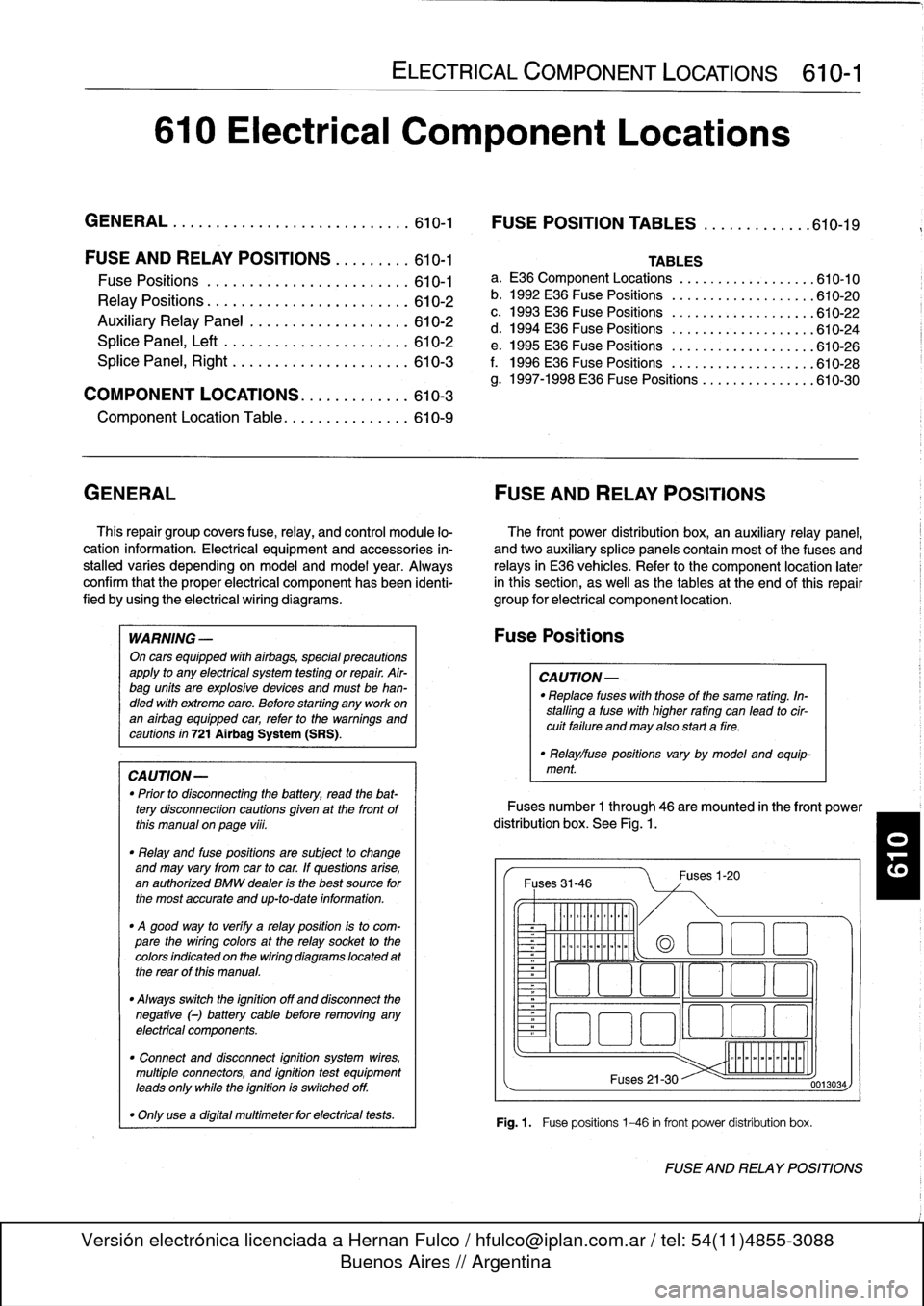
Fuses
number
1
through
46
are
mounted
in
the
front
power
distribution
box
.
See
Fig
.
1.
Fuses
31-46
~
Illlllllllll
°
-
Ilmmlmomlmoi
Fuses
1-20
(a
1
:1
E
El
~
~O!7
L~~n
4~
i
Fuses
21-30
Fig
.1.
Fuse
positions
1-46
in
front
power
distribution
box
.
0013034
FUSE
AND
RELAY
POSITIONS
Page 399 of 759
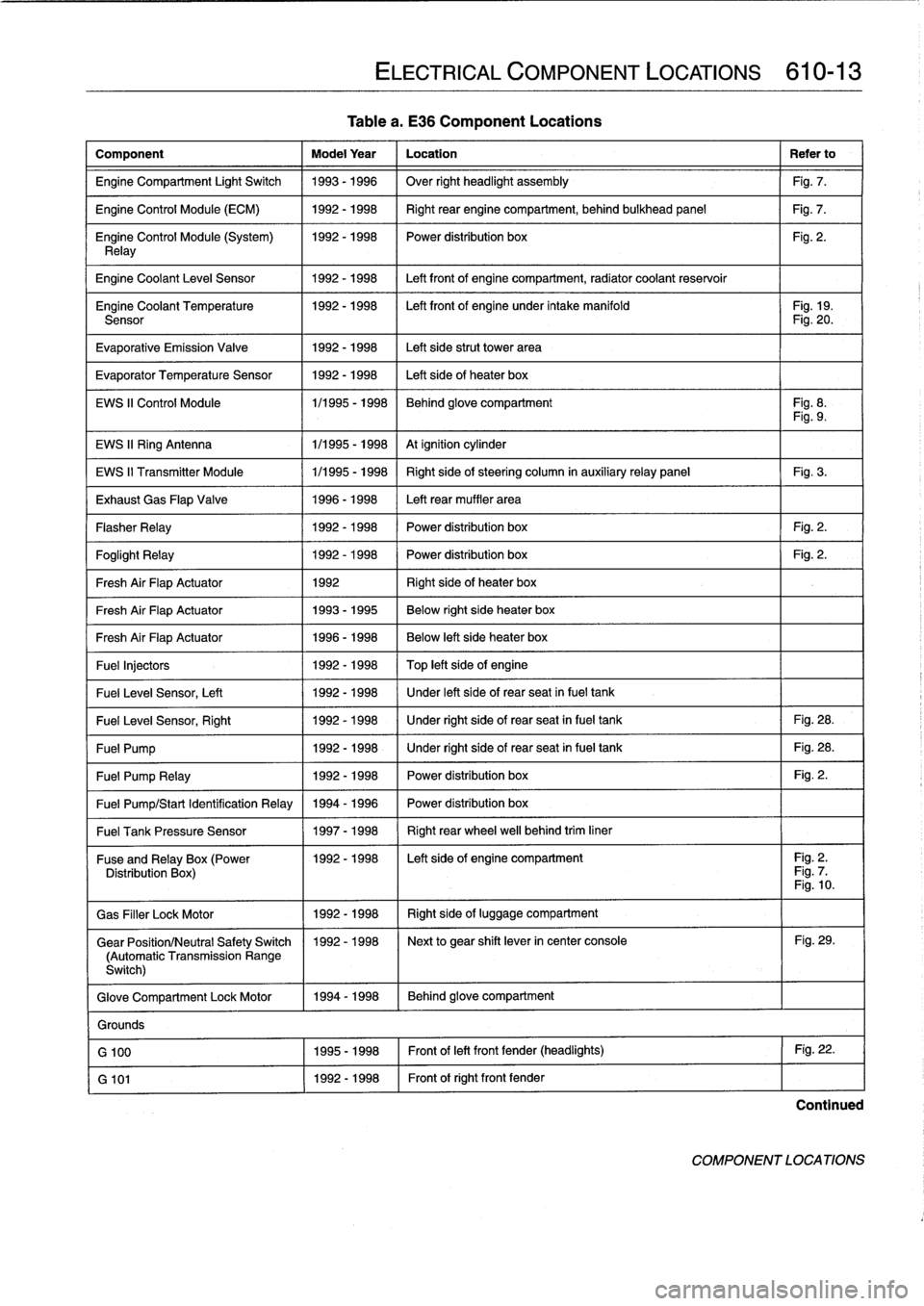
Tablea
.
E36
Component
Locations
Component
Model
Year
Location
Refer
to
Engine
Compartment
Light
Switch
1993-1996
Over
right
headlight
assembly
Fig
.
7
.
Engine
Control
Module
(ECM)
1992-1998
Right
rear
enginecompartment,
behind
bulkhead
panel
Fig
.
7
.
Engine
Control
Module
(System)
1992-1998
I
Power
distribution
box
Fig
.
2
.
Relay
Engine
Coolant
Leve¡
Sensor
1
1992-1998
1
Left
front
of
enginecompartment,
radiator
coolant
reservoir
Engine
Coolant
Temperature
1992-1998
I
Left
front
of
engine
under
intake
manifold
I
Fig
.
19
.
Sensor
Fig
.
20
.
Evaporative
Emission
Valve
1992-1998
Left
side
strut
Power
area
Evaporator
Temperature
Sensor
1992-1998
Left
side
of
heater
box
EWS
II
Control
Module
1/1995
-
1998
Behind
glove
compartment
Fig
.
8
.
Fig
.
9
.
EWS
II
Ring
Antenna
1
1/1995
-
1998
1
At
ignition
cylinder
EWS
II
Transmitter
Module
1/1995
-
1998
Right
side
of
steering
column
in
auxiliaryrelay
panel
Fig
.
3
.
Exhaust
Gas
Flap
Valve
1996-1998
Left
rear
muffler
area
Flasher
Relay
1992-1998
Power
distribution
box
Fig
.
2
.
Foglight
Relay
1
1992-1998
1
Power
distribution
box
1
Fig
.
2
.
Fresh
Air
FlapActuator
1
1992
1
Right
side
of
heater
box
Fresh
Air
FlapActuator
1
1993-1995
1
Below
right
side
heater
box
Fresh
Air
FlapActuator
1
1996-1998
Below
left
side
heater
box
Fuel
Injectors
1992
-
1998
Top
left
side
of
engine
Fuel
Leve¡
Sensor,
Left
1
1992-1998
/
Under
left
side
of
rear
seat
infuel
tank
Fuel
Leve¡
Sensor,
Right
1
1992-1998
1
Under
right
side
of
rear
seat
in
fuel
tank
1
Fig
.
28
.
Fuel
Pump
1
1992-1998
1
Under
right
side
of
rear
seat
in
fuel
tank
1
Fig
.
28
.
Fuel
Pump
Relay
1
1992-1998
1
Power
distribution
box
1
Fig
.
2
.
Fuel
Pump/Start
Identification
Relay
1994
-
1996
Power
distribution
box
Fuel
Tank
Pressure
Sensor
1
1997-1998
1
Right
rear
wheel
well
behind
trim
liner
ELECTRICAL
COMPONENT
LOCATIONS
610-13
Fuse
andRelay
x(Power
11992-1998
I
Left
side
of
engine
compartment
I
Fig
.
2
.
Distribution
Box
Fig
.
7
Fig
.
10
.
Gas
Filler
LockMotor
1992-1998
Right
side
of
luggage
compartment
Gear
Position/Neutral
Safety
Switch
1992-1998
Next
to
gear
shift
lever
in
center
console
Fig
.
29
.
(Automatic
Transmission
Range
Switch)
Glove
Compartment
Lock
Motor
1994-1998
Behind
glove
compartment
Grounds
G
100
1995-1998
Front
of
left
front
fender
(headlights)
Fig
.
22
.
G
101
1992-1998
Front
of
right
front
fender
Continued
COMPONENT
LOCATIONS