ecm relay location BMW 323i 1998 E36 Workshop Manual
[x] Cancel search | Manufacturer: BMW, Model Year: 1998, Model line: 323i, Model: BMW 323i 1998 E36Pages: 759
Page 154 of 759
130-
8
FUEL
INJECTION
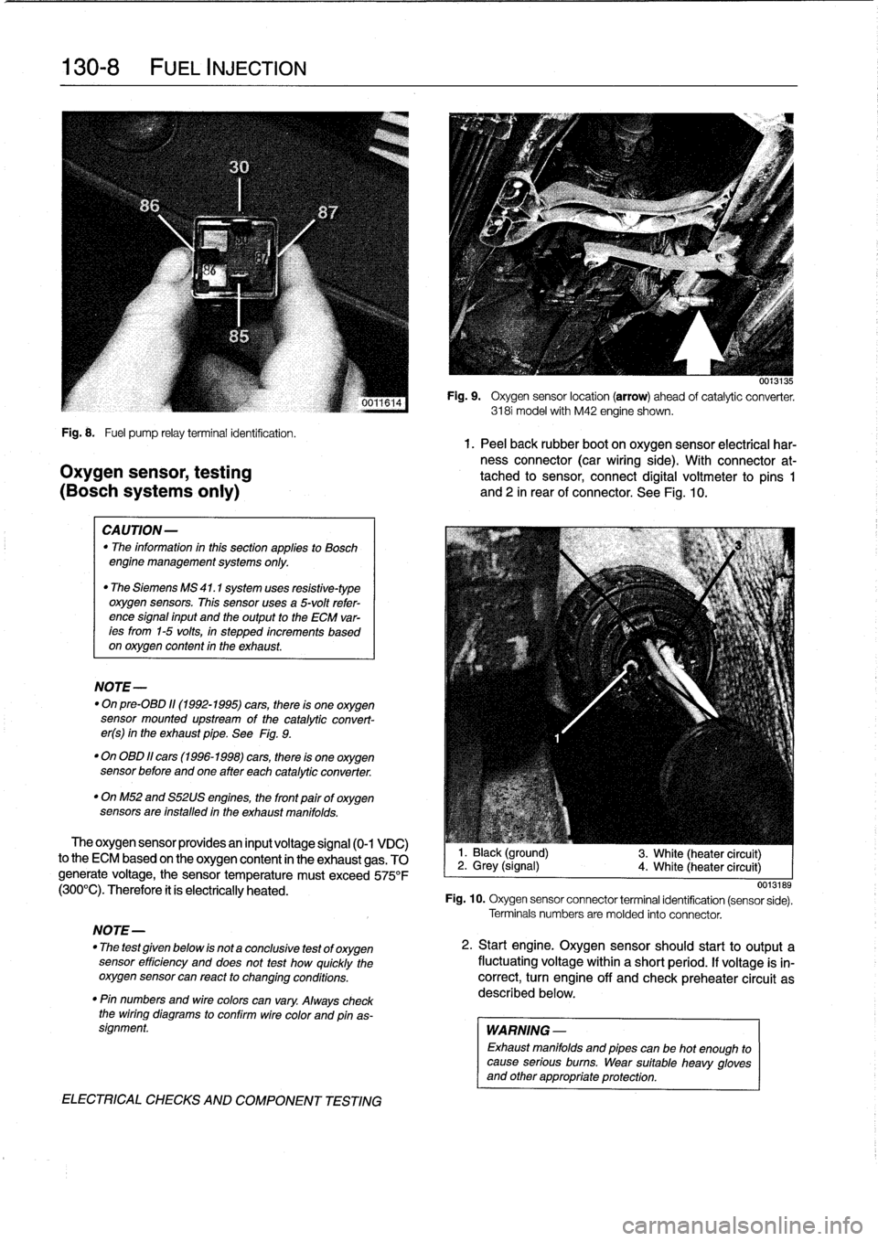
Fig
.
8
.
Fuel
pump
relayterminal
identification
.
1.
Peel
back
rubber
boot
on
oxygen
sensor
electrical
har-
ness
connector
(car
wiring
side)
.
With
connector
at-
Oxygen
sensor,
testing
tached
to
sensor,
connect
digital
voltmeter
to
pins
1
(BOSch
systems
only)
and
2
in
rear
of
connector
.
See
Fig
.
10
.
CAUTION-
"
The
information
inthis
sectionapplies
to
Bosch
engine
management
systems
only
.
"
The
Siemens
MS
41
.1
system
uses
resistive-type
oxygen
sensors
.
This
sensor
uses
a
5-volt
refer-
ence
signal
input
and
the
output
to
the
ECM
var-
ees
from
1-5
volts,
in
stepped
increments
based
on
oxygen
content
in
the
exhaust
.
NOTE-
"
On
pre-08D
11(1992-1995)
cars,
there
is
one
oxygen
sensor
mounted
upstream
of
the
catalytic
convert-
er(s)
in
the
exhaust
pipe
.
See
Fig
.
9
.
"
On
OBD
11
cars
(1996-1998)
cars,
there
is
one
oxygen
sensor
before
andone
after
each
catalytic
converter
.
"
OnM52
and
S52US
engines,
the
front
pairof
oxygen
sensors
are
installed
in
the
exhaust
manifolds
.
The
oxygen
sensor
providesan
input
voltage
signal
(0-1
VDC)
to
the
ECM
based
on
the
oxygen
content
in
the
exhaust
gas
.
TO
generate
voltage,
the
sensor
temperature
must
exceed
575°F
(300°C)
.
Therefore
it
ís
electrically
heated
.
NOTE-
"
The
test
given
below
is
not
a
conclusive
test
of
oxygen
sensor
efficiency
and
does
not
test
how
quickly
the
oxygensensor
can
react
to
changing
conditions
.
"
Pin
numbers
and
wirecolors
can
vary
.
Always
check
the
wiring
diagrams
to
conflrm
wire
color
and
pinas-
signment
.
ELECTRICAL
CHECKS
AND
COMPONENT
TESTING
0013135
Fig
.
9
.
Oxygen
sensor
location
(arrow)
ahead
of
catalytic
converter
.
3181
model
with
M42
engine
shown
.
1
.
Black
(ground)
2
.
Grey
(signal)
4
.
White
(heater
circuit)
3
.
White
(heater
circuit)
0013189
Fig
.
10
.
Oxygen
sensor
connector
terminal
identification
(sensor
sede)
.
Terminals
numbers
are
molded
into
connector
.
2
.
Start
engine
.
Oxygen
sensorshould
start
to
output
a
fluctuating
voltage
within
a
short
period
.
If
voltage
is
in-
correct,
turn
engine
off
and
check
preheater
circuit
as
described
below
.
WARNING
-
Exhaust
manifolds
and
pipes
can
be
hot
enough
to
cause
serious
burns
.
Wear
suitable
heavy
gloves
and
other
appropriate
protection
.
Page 155 of 759
Oxygen
Sensor
FUEL
DELIVERY
TESTS
FUEL
INJECTION
130-
9
"
Voltage
at
¡dle
..
.
..
..
....
0
.2
to
0
.8
VDC,
fluctuating
Checking
fuel
delivery
is
afundamental
part
of
trouble-
shooting
and
diagnosing
the
engine
management
system
.
Fuel
pressure
directly
influences
fuel
delivery
.
An
accurate
NOTE-
fuel
pressure
gauge
will
be
needed
to
make
the
tests
.
To
check
sensorresponse
to
lean
and
rich
mixtures,
createenairleak,
orpull
vacuumhoseofffue¡
pressure
There
are
three
significant
fuel
delivery
values
to
be
mea-
regulator
to
increase
fuel
pressure
.
sured
:
3
.
Separate
sensorharness
connector
from
sensor
.
Check
for
battery
voltage
between
terminals
3
and
4
(green
wire
and
brown
wire)
in
main
wiring
harness
side
of
con-
nector
with
engine
running
.
If
voltage
is
not
present,
check
oxygen
sensor
heater
relay
.
See610
Electrical
Component
Locations
.
4
.
Check
heater
element
resistance
between
terminals
3
and
4
in
sensor
side
of
connector
.
If
element
is
electri-
cally
open
(no
continuity),
replace
sensor
.
NOTE-
The
oxygen
sensor
heater
relay
is
mounted
in
the
main
power
distributfon
box
in
the
left
rear
of
the
engine
com-
partment
.
Refer
to
Fig
.
6
.
The
heater
relay
is
energized
wíth
positive
(+)
battery
voltage
from
the
main
relayanda
switched
ground
from
the
ECM
.
See
Electrical
Wir-
ing
Diagrams
.
"
Oxygen
sensor
to
exhaust
pipe
...
..
55
Nm
(41
ft-Ib)
"
System
pressure-created
by
the
fuel
pump
and
main-
tained
by
the
pressure
regulator
.
"
Fuel
delivery
volume-created
by
the
fuel
pump
and
af-
fected
by
restrictions,
suchasclogged
fuel
filter
.
"
Residual
pressure-the
pressure
maintained
in
the
closed
system
after
the
engine
and
fuel
pump
are
shut
off
.
Procedures
for
measuring
the
first
two
quantities
arede-
scribed
in
160
Fuel
Tank
and
Fuel
Pump
.
Residual
fuel
pres-
sure
is
checked
using
the
procedure
detailed
later
in
this
group
.
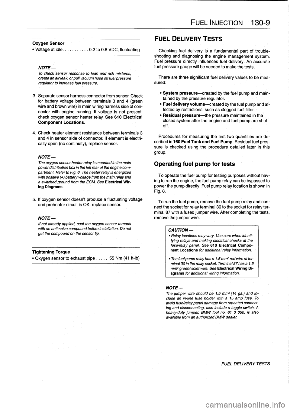
Operating
fuel
pump
fortests
To
operate
the
fuel
pump
for
testing
purposes
without
hav-
íng
to
runthe
engine,
the
fuel
pump
relay
can
be
bypassed
to
power
the
pump
directly
.
Fuel
pump
relay
location
is
shown
in
Fig
.
6
.
5
.
¡f
oxygen
sensor
doesn't
produce
a
fluctuating
voltage
To
runthe
fuel
pump,
remove
the
fuel
pump
relay
and
con-
and
preheater
circuit
is
OK,
replace
sensor
.
nect
the
socket
for
relayterminal
30
to
the
socket
for
relay
ter-
mina¡
87
with
a
fused
jumper
wire
.
After
completing
the
tests,
NOTE-
remove
the
jumper
wire
.
If
not
already
applied,
coat
the
oxygen
sensor
threads
with
an
anti-seize
compound
before
installation
.
Do
not
CAUTION-
getthe
compound
on
the
sensor
tip
.
"
Relay
locations
may
vary
.
Use
care
when
identi-
fying
relays
and
making
electrical
checks
at
the
fuselrelay
panel
.
See
610
Electrical
Compo
Tightening
Torque
nent
Locations
for
additional
relay
information
.
"
The
fuel
pump
relay
has
a
1
.5
mm2
red
wire
at
ter-
minal
30
in
the
relay
socket
.
Terminal
87
has
a
1
.5
mm
2
greenlviolet
wire
.
See
Electrical
Wiring
Di-
agrams
for
additional
wiring
information
.
NOTE-
Thejumper
wire
should
be
1.5
mm2
(14
ga
.)
and
in-
clude
an
in-line
tuse
holder
with
a15
amp
tuse
.
To
avoid
fuselrelay
panel
damage
from
repeated
connect-
ing
and
disconnecting,
also
include
a
toggle
switch
.
A
heavy-duty
jumper,
BMW
tool
no
.
61
3
050,
is
also
available
from
an
authorized
BMW
dealer
.
FUEL
DELIVERYTESTS
Page 160 of 759
130-
1
4
FUEL
INJECTION
NOTE-
Be
sure
to
retrieve
thrust
washer
behind
fuel
pressure
regulator
on
6-cylinder
engine
.
4
.
Installation
is
reverse
of
removal
.
Replace
O-rings
.
Fuel
pressure
regulator,
replacing
(under
car
mount)
WARNING
-
Fuel
will
be
discharged
.
Do
not
disconnect
any
wires
that
could
cause
electrical
sparks
.
Do
not
smoke
or
work
near
heaters
or
other
fire
hazards
.
Keep
an
approved
tire
extinguisher
handy
.
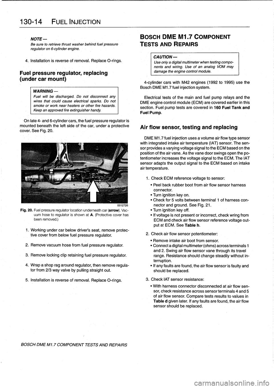
On
late
4-
and
6-cylinder
cars,
the
fuel
pressure
regulator
is
mounted
beneath
the
left
sideof
the
car,
under
a
protective
cover
.
See
Fig
.
20
.
0012726
Fig
.
20
.
Fuel
pressure
regulatorlocation
underneath
car
(arrow)
.
Vac-
uum
hose
to
regulator
is
shown
at
A
.
(Protective
cover
has
been
removed
.)
5
.
Installation
is
reverse
of
removal
.
Replace
O-rings
.
BOSCH
DME
Ml
.
7
COMPONENT
TESTS
AND
REPAIRS
BOSCH
DME
Ml
.7
COMPONENT
TESTS
AND
REPAIRS
CA
UTION-
Use
only
a
digital
multimeter
when
testing
compo-
nents
and
wiring
.
Use
of
an
analog
VOM
may
damage
the
engine
control
module
.
4-cylinder
cars
with
M42
engines(1992
to
1995)use
the
Bosch
DME
M1
.7
fuel
injection
system
.
Electrical
tests
of
the
main
and
fuel
pump
relays
and
the
DME
engine
control
module
(ECM)
are
covered
earlier
in
this
section
.
Fuel
pump
tests
arecovered
in
160
Fuel
Tank
and
Fuel
Pump
.
Air
flow
sensor,
testing
and
replacing
DME
M1
.7
fuel
injection
uses
a
volume
air
flow
type
sensor
with
integrated
intake
air
temperature
(IAT)
sensor
.
The
sen-
sor
provides
a
varyingvoltage
signal
to
the
ECM
based
on
the
position
of
the
air
vane
.
As
the
vane
doorswings
open
thepo-
tentiometer
increases
the
voltage
signal
to
the
ECM
.
The
IATsensor
adapts
theoutput
signal
to
the
ECM
based
on
intake
air
temperature
.
1
.
Check
ECM
reference
voltage
to
sensor
:
"
Peel
back
rubber
boot
from
air
flow
sensor
harness
connector
.
"
Turn
ignition
keyon
.
"
Check
for
5
volts
between
terminal
1
of
harness
con-
nector
and
ground
.
See
Fig
.
21
.
"
Turn
ignition
key
off
.
"
If
voltage
is
not
present
or
incorrect,
check
wring
from
ECM
and
check
air
flow
sensor
reference
voltage
out-
put
at
ECM
.
See
Table
h
.
1
.
Working
under
car
below
driver's
seat,
remove
protec-
tive
cover
from
below
fuel
pressure
regulator
.
"
Remove
intake
air
bootfrom
sensor
.
2
.
Remove
vacuum
hosefrom
fuel
pressure
regulator
.
"
Connect
a
digital
multimeter
(ohms)
across
terminais
1
and
2
.
Swing
air
flow
sensor
vane
through
its
travel
3
.
Remove
locking
clip
retaining
fuel
pressure
regulator
.
range
.
Resistance
should
change
steadily
without
in-
terruption
.
4
.
Wrap
a
shop
rag
around
regulator,
then
remove
regula-
"
If
any
faults
are
found,
the
air
flow
sensor
is
faulty
and
tor
from
213
way
valve
by
pullingstraight
out
.
should
be
replaced
.
2
.
Check
air
flow
sensor
potentiometer
:
3
.
Check
IAT
sensor
resistance
:
"
With
harness
connector
disconnected
at
air
flow
sen-
sor,
check
resistance
across
sensor
terminais
4
and
5
of
air
flow
sensor
.
Compare
tests
results
to
values
in
Table
d
given
later
.
If
any
faults
are
found,
the
air
flow
sensor
should
be
replaced
.
Page 164 of 759
130-18
FUEL
INJECTION
The
engine
coolant
temperature
(ECT)
sensor
sends
con-
tinuous
engine
coolant
temperature
information
to
the
ECM
.
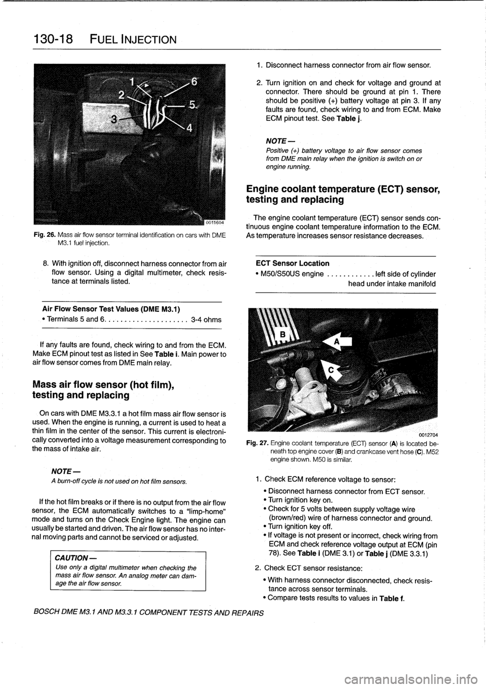
Fig
.
26
.
Mass
air
flow
sensor
terminalidentifcation
on
carswith
DME
As
temperature
increases
sensor
resistance
decreases
.
M3
.1
fuel
injection
.
Mass
air
flow
sensor
(hot
film),
testing
and
replacing
MOTE-
A
burn-off
cycle
is
not
used
on
hot
film
sensors
.
8
.
With
ignition
off,
disconnect
harness
connector
from
air
ECT
Sensor
Location
flow
sensor
.
Using
a
digital
multimeter,
check
resis-
"
M50/S50US
engine
............
left
side
of
cylinder
tance
at
terminals
listed
.
head
under
intake
manifold
Air
Flow
Sensor
Test
Values
(DMEM3
.1)
"
Terminals
5
and
6
.
.
.
.........
..
.
..
....
3-4
ohms
If
any
faults
are
found,
check
wiring
lo
and
from
the
ECM
.
Make
ECM
pinout
test
as
listed
in
See
Table
i
.
Main
power
to
air
flow
sensor
comes
from
DME
main
relay
.
On
cars
with
DME
M3
.3
.1
a
hot
film
mass
air
flow
sensor
is
used
.
When
the
engine
is
running,
a
current
is
used
lo
heat
a
thinfilm
in
the
center
of
the
sensor
.
This
current
is
electroni-
cally
converted
into
a
voltage
measurement
corresponding
to
the
mass
of
intake
air
.
If
thehot
film
breaks
or
if
there
is
no
output
from
the
air
flow
sensor,
the
ECM
automatically
switches
to
a
"limp-home"
mode
and
tucos
on
the
Check
Engine
light
.
The
engine
can
usually
be
started
and
driven
.
The
air
flow
sensor
has
no
inter-
nal
moving
parts
and
cannot
be
senricedor
adjusted
.
CA
UTION-
Use
only
a
digital
multimeter
when
checking
the
mass
air
flow
sensor
.
An
analogmetercan
dam-
age
the
air
flow
sensor
.
BOSCH
DME
M3
.
1
AND
M32
.1
COMPONENT
TESTS
AND
REPAIRS
1
.
Disconnect
harnessconnector
from
air
flow
sensor
.
2
.
Turn
ignition
on
and
check
for
voltage
and
ground
at
connector
.
There
should
beground
at
pin
1
.
There
should
be
positive
(+)
battery
voltage
at
pin
3
.
If
any
faults
are
found,
check
wiring
to
and
from
ECM
.
Make
ECM
pinout
test
.
See
Table
j
.
NOTE-
Positive
(+)
battery
voltage
to
air
flow
sensor
comes
from
DME
main
relay
when
the
ignition
is
switch
on
orengine
running
.
Engine
coolant
temperature
(ECT)
sensor,
testing
and
replacing
0012704
Fig
.
27
.
Engine
coolant
temperature
(ECT)
sensor
(A)
is
located
be-
neath
top
engine
cover
(B)
and
crankcase
vent
hose
(C)
.
M52
engine
shown
.
M50
is
similar
.
1
.
Check
ECM
reference
voltage
to
sensor
:
"
Disconnect
harnessconnector
from
ECT
sensor
.
"
Turn
ignition
keyon
.
"
Check
for
5
volts
between
supply
voltage
wire
(brown/red)
wire
of
harness
connector
and
ground
.
"
Turn
ignition
key
off
.
"
If
voltage
is'
not
present
or
incorrect,
check
wiring
from
ECM
and
check
referencevoltage
output
at
ECM
(pin
78)
.
See
Table
i
(DM
E
3
.1)
or
Table
j
(DME
3
.3
.1)
2
.
Check
ECT
sensor
resistance
:
"
With
harnessconnector
disconnected,
check
resis-
tance
acrosssensor
terminals
.
"
Compare
tests
results
to
values
in
Table
f
.
Page 190 of 759
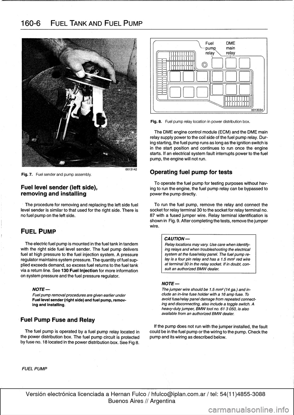
160-
6
FUEL
TANK
AND
FUEL
PUMP
Fig
.
7
.
Fuel
sender
and
pump
assembly
.
To
operate
the
fuel
pump
for
testing
purposes
without
hav-
Fuel
leve¡
sender
(left
side),
ing
to
runthe
engine,
the
fuel
pump
relay
can
be
bypassed
to
removing
and
installing
powerthe
pump
directly
.
The
procedure
for
removing
and
replacing
the
left
side
fuel
To
runthe
fuel
pump,
remove
the
relay
and
connect
the
leve¡
sender
is
similar
tothat
used
for
the
right
side
.
There
is
socket
for
relayterminal
30
to
the
socket
for
relay
terminal
no
.
no
fuel
pump
on
the
left
side
.
87
with
afused
jumper
wire
.
Relay
terminal
identification
is
shown
in
Fig
.
9
.
After
completing
the
tests,
remove
the
jumper
wire
.
FUEL
PUMP
The
electric
fuel
pump
ís
mounted
in
the
fuel
tank
in
tandem
with
the
right
side
fuelleve¡
sender
.
The
fuel
pump
delivers
fuel
at
high
pressure
to
the
fuel
injection
system
.
A
pressure
regulator
maintains
system
pressure
.
The
quantity
of
fuel
sup-
plied
exceeds
demand,
so
excess
fuel
retums
to
the
fuel
tank
via
a
retum
líne
.
See
130
Fuel
Injection
for
more
information
on
system
pressure
and
the
fuel
pressure
regulator
.
NOTE
-
Fuel
pump
removalprocedures
are
given
earlier
under
Fuel
leve¡
sender
(right
side)
and
fuel
pump,
remov-
íng
and
installing
.
Fuel
Pump
Fuse
and
Relay
The
fuel
pump
is
operated
by
a
fuel
pump
relay
located
ín
the
power
distribution
box
.
The
fuel
pump
circuit
is
protected
by
fuse
no
.
18
located
in
the
power
distribution
box
.
See
Fig
8
.
FUEL
PUMP
0013142
Fuel
DM
E
PUMP
main
re
ay
rel
ay
0
aoo
o
~a
aao
ó
Fig
.
8
.
Fuel
pump
relay
location
in
power
distribution
box
.
The
DME
engine
control
module
(ECM)
and
the
DME
main
relay
supply
power
to
the
coi¡
sideof
the
fuel
pump
relay
.
Dur-
ing
starting,
the
fuel
pump
runs
as
long
as
the
ignition
switch
is
in
the
start
position
and
continues
to
run
oncethe
engine
starts
.
If
an
electrical
system
fault
interrupts
power
to
the
fuel
pump,
the
engine
will
notrun
.
Operating
fuel
pump
for
tests
CA
UTION-
Relay
locations
may
vary
.
Use
care
when
identify-
ing
relays
and
when
troubleshooting
the
electrical
system
at
the
fuselrelay
panel
.
The
fuel
pump
re-
¡ay
is
a
four
pin
relay
and
has
a
1.5
mm
2
red
wireat
terminal
30
in
the
relay
socket,
lf
in
doubt,
con-
sult
an
authorized
BMW
dealer
.
NOTE-
Thejumper
wire
shouldbe
1.5
mm2
(14
ga
.)
and
in-
clude
en
in-fine
fuse
holder
with
a16
amp
fuse
.
To
avoid
fuselrelay
panel
damage
fromrepeated
connect-
íng
and
disconnecting,
also
include
a
toggleswitch
.
A
heavy-duty
jumper,
BMW
tool
no
.
613
050,
fs
also
available
from
en
authorized
BMW
dealer
.
0013034,
If
the
pump
does
notrun
with
the
jumper
installed,
the
fault
could
be
in
the
fuel
pump
or
the
wiring
to
the
pump
.
Check
the
pump
and
its
wiring
as
described
below
.
Page 399 of 759
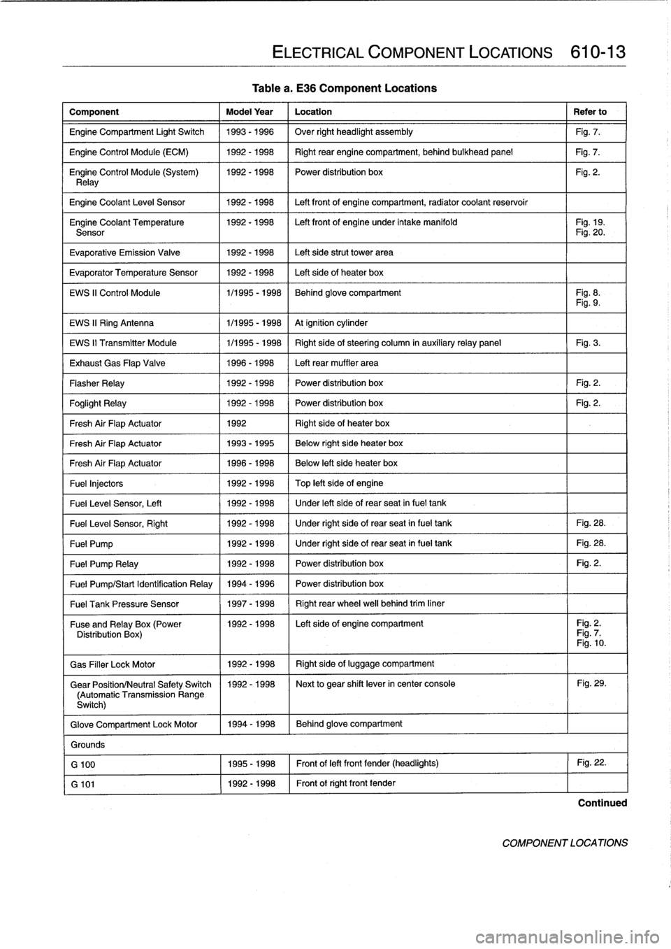
Tablea
.
E36
Component
Locations
Component
Model
Year
Location
Refer
to
Engine
Compartment
Light
Switch
1993-1996
Over
right
headlight
assembly
Fig
.
7
.
Engine
Control
Module
(ECM)
1992-1998
Right
rear
enginecompartment,
behind
bulkhead
panel
Fig
.
7
.
Engine
Control
Module
(System)
1992-1998
I
Power
distribution
box
Fig
.
2
.
Relay
Engine
Coolant
Leve¡
Sensor
1
1992-1998
1
Left
front
of
enginecompartment,
radiator
coolant
reservoir
Engine
Coolant
Temperature
1992-1998
I
Left
front
of
engine
under
intake
manifold
I
Fig
.
19
.
Sensor
Fig
.
20
.
Evaporative
Emission
Valve
1992-1998
Left
side
strut
Power
area
Evaporator
Temperature
Sensor
1992-1998
Left
side
of
heater
box
EWS
II
Control
Module
1/1995
-
1998
Behind
glove
compartment
Fig
.
8
.
Fig
.
9
.
EWS
II
Ring
Antenna
1
1/1995
-
1998
1
At
ignition
cylinder
EWS
II
Transmitter
Module
1/1995
-
1998
Right
side
of
steering
column
in
auxiliaryrelay
panel
Fig
.
3
.
Exhaust
Gas
Flap
Valve
1996-1998
Left
rear
muffler
area
Flasher
Relay
1992-1998
Power
distribution
box
Fig
.
2
.
Foglight
Relay
1
1992-1998
1
Power
distribution
box
1
Fig
.
2
.
Fresh
Air
FlapActuator
1
1992
1
Right
side
of
heater
box
Fresh
Air
FlapActuator
1
1993-1995
1
Below
right
side
heater
box
Fresh
Air
FlapActuator
1
1996-1998
Below
left
side
heater
box
Fuel
Injectors
1992
-
1998
Top
left
side
of
engine
Fuel
Leve¡
Sensor,
Left
1
1992-1998
/
Under
left
side
of
rear
seat
infuel
tank
Fuel
Leve¡
Sensor,
Right
1
1992-1998
1
Under
right
side
of
rear
seat
in
fuel
tank
1
Fig
.
28
.
Fuel
Pump
1
1992-1998
1
Under
right
side
of
rear
seat
in
fuel
tank
1
Fig
.
28
.
Fuel
Pump
Relay
1
1992-1998
1
Power
distribution
box
1
Fig
.
2
.
Fuel
Pump/Start
Identification
Relay
1994
-
1996
Power
distribution
box
Fuel
Tank
Pressure
Sensor
1
1997-1998
1
Right
rear
wheel
well
behind
trim
liner
ELECTRICAL
COMPONENT
LOCATIONS
610-13
Fuse
andRelay
x(Power
11992-1998
I
Left
side
of
engine
compartment
I
Fig
.
2
.
Distribution
Box
Fig
.
7
Fig
.
10
.
Gas
Filler
LockMotor
1992-1998
Right
side
of
luggage
compartment
Gear
Position/Neutral
Safety
Switch
1992-1998
Next
to
gear
shift
lever
in
center
console
Fig
.
29
.
(Automatic
Transmission
Range
Switch)
Glove
Compartment
Lock
Motor
1994-1998
Behind
glove
compartment
Grounds
G
100
1995-1998
Front
of
left
front
fender
(headlights)
Fig
.
22
.
G
101
1992-1998
Front
of
right
front
fender
Continued
COMPONENT
LOCATIONS
Page 752 of 759
WARNING
Your
common
sense,
good
judge-
ment,
and
general
alertness
are
cru-
cial
to
safe
and
successful
service
work
.
Befcre
attempting
any
work
on
your
BMW,
read
the
warnings
and
cautions
on
page
vi¡
and
the
copyright
page
at
the
frontof
the
manual
.
Review
these
warnings
and
cautions
each
time
you
prepare
to
workon
your
BMW
.
Please
also
read
any
warnings
and
cautions
that
accom-
pany
the
procedures
in
the
manual
.
Door
glass
See
Door
windows
Door
windows
general
information
512-1
front
door
window
(2-door
models)
adjusting
512-7
removing/installing
512-5
front
door
window
(4-door
models)
initíalizing
512-1
removing/installing
512-2
rear
door
window
(4-door
models)
removing/installing
512-4
fixed
glass,
removing/installing
512-
4
rear
vent
window
or
vent
latch,
replacing
(2-door
models)
512-11
window
regulator
and
motor,
removing/installing
512-12
window
regulator
service
512-12Doorcheck
See
DoorsDoor
handle
See
Centrallocking
and
anti-theft
Door
panel
See
Doors
Doors
general
information
411-1
door
adjustment
411-2door
check,
replacing
411-2
door
panels
411-3
doors411-1
front
orrear
door,removing/installing
411-1
front
door
panel,
removing/installing
411-3
rear
door
panel,
removing/installing
411-4
rearsidepanel,
removing/installing
(two-door
model)
411-4
Drive
axle
See
Rear
suspension
Driveability
troubleshooting
See
Engine-general
Driveshaft
general
information
260-1
center
bearing
assembly,
replacing
260-6
driveshaft,
aligning
260-3
driveshaft,
installing
260-4
Driveshaft
(cont
.)
driveshaft,
removing260-4
driveshaftservice
260-3
flex-disc,
replacing
260-5
front
centering
guide,
replacing
260-7
guibo
See
flex-disc
troubleshooting260-1
ECM
(engine
control
module)
pin
assignment
See
Fuel
injection
Electrical
circuit
See
Electrical
system-general
Electrical
component
locations
general
information
610-1
auxíliary
relay
panel
610-2
component
location
table
610-9
component
locations
610-3
fuse
position
tables
610-19
fuse
positions
610-1
relay
positions
610-2
splice
panel,
left
610-2
splice
panel,
right
610-3
Electrical
system-general
general
information
600-1
continuity,
checking
600-5
electrical
test
equipment
600-2
safety
precautions
600-1
short
circuits
600-5
short
circuit,
testing
with
ohmmeter
600-6
short
circuit,
testing
with
voltmeter
600-6
troubleshooting
600-3
voltage,
measuring600-4
voltage
and
polarity
600-1
voltage
and
voltage
drops
600-4
voltage
drop,
testing
600-4
wiring
codes
and
abbreviations
600-2
wiring
diagrams
600-2
wiring,
fuses
and
relays
600-1
Electrical
wiring
diagrams
general
information
ELE-1
wiring
diagrams
ELE-2
ABS
ELE-117
ABS/AST
ELE-120
airbag
(supplemental
restraint
system)
ELE-140
air
conditioning
and
heating
ELE-
129
anti-theft
(Alpine)
system
ELE-144
anti-theft
(EWS
II)
ELE-150
body
computer
module
ELE-176
charging
system
ELE-67
convertible
top
ELE-253
cruise
control
ELE-112
data
link
connector
ELE-86
engine
cooling
ELE-94
engine
management
ELE-70
exterior
lights
ELE-194
ground
distribution
ELE-35
headlights/foglights
ELE-180
INDEX
3
Electrical
wiring
diagrams
(cont
.)
heated
seats
ELE-245
horns
ELE-153
instrument
panel
ELE-165
interior
lights/illumination
ELE-211
lumbar
control
ELE-247
on-board
computer
ELE-173
park
ventilation
ELE-139
power
distribution
ELE-2
power
door
locks
ELE-226
power
mirrors
ELE-241
power
seats
ELE-243
power
sunroof
ELE-248
power
windows
ELE-231
radio/cassette/CD/speakers
ELE-
255
rear
window
defogger
ELE-160
shift
interlock
ELE-110
starting
ELE-63
transmission
electronics
ELE-96
warning
systems`
.
chimes
ELE-178
wiper/washer
ELE-154
Emergencies
See
Fundamentals
for
the
do-it-
yourself
owner
Engine-general
general
information
100-1
air
flow
measurement
and
vacuum
leaks
100-12
basic
engine
settings
100-11
basic
requirements
100-11
battery
voltage
100-12connecting
rods
and
pistons
100-1
cooling
system
100-5
cylinder
block
and
crankshaft100-1
cylinder
compression,
checking
100-6
cylinder
head
and
valvetrain
100-2
DISA
(dual
resonance
intake
system)
100-3,130-3
driveability
troubleshooting
100-8
engine
management
system
100-3
fuel
delivery
100-5
fuel
supply
100-14ground
connections
100-13
ignition
100-5
lubrication
system100-5
mechanical
troubleshooting
100-5
on-board
diagnostics
(OBD)
100-8
oxygen
sensors
100-11
preventive
maintenance
100-11
VANOS
(variable
valve
timing)
100-2warningsand
cautions
100-5
wiring
andharness
connections100-
13Engine
control
module
(ECM)
See
Fuel
injection
Engine
removal
and
installation
general
information
110-1
engine,
removing/installing(4-cylinder
engines)
110-1
engine,
removing/installing
(6-cylinder
engines)
110-4
Engine
coolant
temperature
(ECT)
sensor
See
Fuel
injection
Engine
hood
See
Fenders,
enginehood