power distribution box location BMW 323i 1998 E36 Workshop Manual
[x] Cancel search | Manufacturer: BMW, Model Year: 1998, Model line: 323i, Model: BMW 323i 1998 E36Pages: 759
Page 190 of 759
160-
6
FUEL
TANK
AND
FUEL
PUMP
Fig
.
7
.
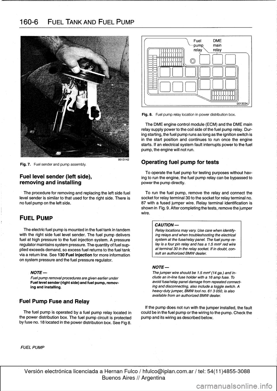
Fuel
sender
and
pump
assembly
.
To
operate
the
fuel
pump
for
testing
purposes
without
hav-
Fuel
leve¡
sender
(left
side),
ing
to
runthe
engine,
the
fuel
pump
relay
can
be
bypassed
to
removing
and
installing
powerthe
pump
directly
.
The
procedure
for
removing
and
replacing
the
left
side
fuel
To
runthe
fuel
pump,
remove
the
relay
and
connect
the
leve¡
sender
is
similar
tothat
used
for
the
right
side
.
There
is
socket
for
relayterminal
30
to
the
socket
for
relay
terminal
no
.
no
fuel
pump
on
the
left
side
.
87
with
afused
jumper
wire
.
Relay
terminal
identification
is
shown
in
Fig
.
9
.
After
completing
the
tests,
remove
the
jumper
wire
.
FUEL
PUMP
The
electric
fuel
pump
ís
mounted
in
the
fuel
tank
in
tandem
with
the
right
side
fuelleve¡
sender
.
The
fuel
pump
delivers
fuel
at
high
pressure
to
the
fuel
injection
system
.
A
pressure
regulator
maintains
system
pressure
.
The
quantity
of
fuel
sup-
plied
exceeds
demand,
so
excess
fuel
retums
to
the
fuel
tank
via
a
retum
líne
.
See
130
Fuel
Injection
for
more
information
on
system
pressure
and
the
fuel
pressure
regulator
.
NOTE
-
Fuel
pump
removalprocedures
are
given
earlier
under
Fuel
leve¡
sender
(right
side)
and
fuel
pump,
remov-
íng
and
installing
.
Fuel
Pump
Fuse
and
Relay
The
fuel
pump
is
operated
by
a
fuel
pump
relay
located
ín
the
power
distribution
box
.
The
fuel
pump
circuit
is
protected
by
fuse
no
.
18
located
in
the
power
distribution
box
.
See
Fig
8
.
FUEL
PUMP
0013142
Fuel
DM
E
PUMP
main
re
ay
rel
ay
0
aoo
o
~a
aao
ó
Fig
.
8
.
Fuel
pump
relay
location
in
power
distribution
box
.
The
DME
engine
control
module
(ECM)
and
the
DME
main
relay
supply
power
to
the
coi¡
sideof
the
fuel
pump
relay
.
Dur-
ing
starting,
the
fuel
pump
runs
as
long
as
the
ignition
switch
is
in
the
start
position
and
continues
to
run
oncethe
engine
starts
.
If
an
electrical
system
fault
interrupts
power
to
the
fuel
pump,
the
engine
will
notrun
.
Operating
fuel
pump
for
tests
CA
UTION-
Relay
locations
may
vary
.
Use
care
when
identify-
ing
relays
and
when
troubleshooting
the
electrical
system
at
the
fuselrelay
panel
.
The
fuel
pump
re-
¡ay
is
a
four
pin
relay
and
has
a
1.5
mm
2
red
wireat
terminal
30
in
the
relay
socket,
lf
in
doubt,
con-
sult
an
authorized
BMW
dealer
.
NOTE-
Thejumper
wire
shouldbe
1.5
mm2
(14
ga
.)
and
in-
clude
en
in-fine
fuse
holder
with
a16
amp
fuse
.
To
avoid
fuselrelay
panel
damage
fromrepeated
connect-
íng
and
disconnecting,
also
include
a
toggleswitch
.
A
heavy-duty
jumper,
BMW
tool
no
.
613
050,
fs
also
available
from
en
authorized
BMW
dealer
.
0013034,
If
the
pump
does
notrun
with
the
jumper
installed,
the
fault
could
be
in
the
fuel
pump
or
the
wiring
to
the
pump
.
Check
the
pump
and
its
wiring
as
described
below
.
Page 191 of 759
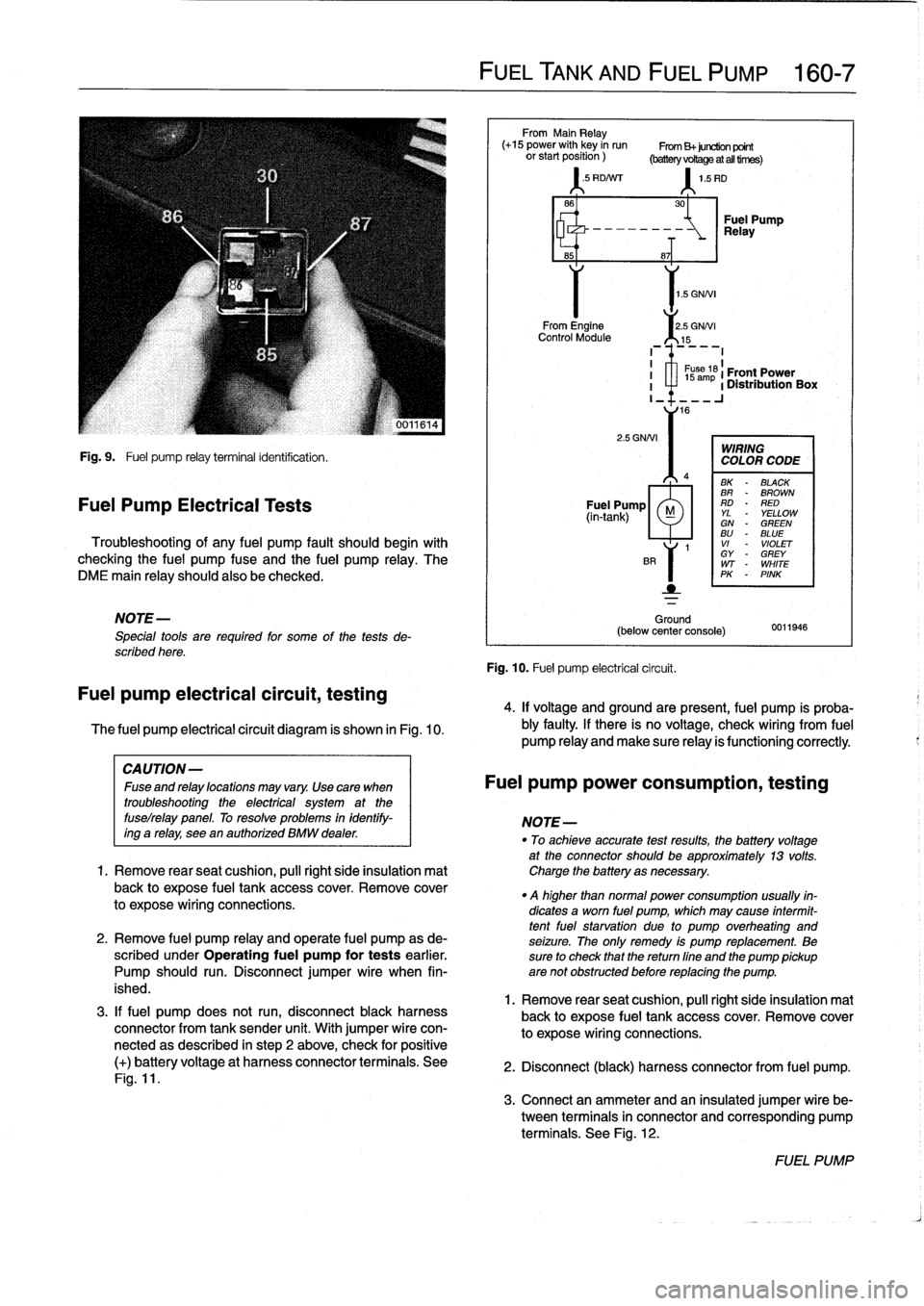
Fig
.
9
.
Fuel
pump
relay
terminal
identification
.
Fuel
Pump
Electrical
Tests
Troubleshooting
of
any
fuel
pump
fault
should
begin
with
checking
the
fuel
pump
fuse
and
the
fuel
pump
relay
.
The
DME
main
relay
should
also
be
checked
.
NOTE-
Special
tools
are
requíred
for
some
of
the
tests
de-
scribed
here
.
Fuel
pump
electrical
circuit,
testing
The
fuel
pump
electrical
circuit
diagram
is
shown
in
Fig
.
10
.
3
.
If
fuel
pump
does
not
run,
disconnect
black
harness
connector
from
tank
sender
unit
.
With
jumper
wire
con-
nectedas
described
in
step
2
above,
check
for
positive
(+)
batteryvoltage
at
harness
connector
terminals
.
See
Fig
.
11
.
FUEL
TANK
AND
FUEL
PUMP
160-
7
From
Main
Relay
(+15
power
with
key
in
run
From
B+juretion
point
orstartposition)
(batteryvoRageatalltirnes)
'
.5
RD/Nrr
1
.5
RD
1
.5
GNNI
From
Engine
2
.5
GNNI
Control
Module
15
2
.5
GNNI
Ground
(below
center
console)
Fig
.
10
.
Fuel
pump
electrical
circuit
.
30
-~
Relay
Fuel
Pump
8~T
I
1
s
ám
61
Front
Power
I
a
1
Distribution
Box
I_
16
WIRING
COLOR
CODE
BK
-
BLACK
BR
-
BROWN
Fuel
Pump
RD
-
RED
(in-tank)
M
YL
YELLOWGN
-
GREENBU
-
BLUE
1
VI
-
VIOLET
GY
-
GREY
WT
-
WHITE
PK
-
PINK
0011946
4
.
If
voltage
and
groundare
present,
fuel
pump
is
proba-
bly
faulty
.
If
there
is
no
voltage,
check
wiring
From
fuel
pump
Reay
and
make
sure
Reay
is
functioning
correctly
.
CAUTION-
Fuseandrelaylocationsmayvary
.
Usecara
when
Fuel
pump
power
consumption,
testing
troubleshooting
the
electrical
system
at
the
fuselrelay
panel
.
To
resolve
problems
in
identify-
NOTE-
ing
a
relay,
see
en
authorízed
BMW
dealer
.
"
To
achieveaccurate
testresults,
fhe
battery
voltage
at
the
connector
should
be
approximately
13
volts
.
1.
Remove
rearseat
cushion,
pull
right
side
insulation
mat
Charge
the
battery
asnecessary
.
back
to
expose
fuel
tank
accesscover
.
Remove
cover
.
q
higher
than
normal
power
consumption
usually
fin-
to
expose
wiring
connections
.
dicates
a
worn
fuel
pump,
which
may
cause
intermit-
tentfuel
starvation
due
lo
pump
overheating
and
2
.
Remove
fuel
pump
relay
and
opérate
fuel
pump
as
de-
seizure
.
The
only
remedy
is
pump
replacement
.
Be
scribed
under
Operating
fuel
pump
for
tests
earlier
.
sure
to
check
that
thereturn
fine
and
the
pump
pickup
Pump
should
run
.
Disconnect
jumper
wire
when
fin-
are
not
obstructed
before
replacing
the
pump
.
ished
.
1
.
Remove
rear
seat
cushion,
pull
right
side
insulation
mal
back
to
expose
fuel
tank
accesscover
.
Remove
cover
to
expose
wiring
connections
.
2
.
Disconnect
(black)
harness
connector
from
fuel
pump
.
3
.
Connect
an
ammeter
and
an
insulated
jumper
wire
be-
tween
terminals
in
connector
and
corresponding
pump
terminals
.
See
Fig
.
12
.
FUEL
PUMP
Page 199 of 759
NOTE-
Some
cars
covered
by
this
manual
may
have
an
alter-
nate
cooling
fan
switchwith
switching
temperatures
of
176%190W
(80%88°C)
.
When
replacing
the
switch
check
theswitching
specifications,
whichshouldbe
stamped
on
the
switch
body
.
1
.
If
coolant
is
circulating
at
normal
operating
tempera-
ture,
but
auxiliary
cooling
fan
does
not
run,
disconnect
connector
from
radiator
temperature
switch
and
make
tests
listed
in
Table
c
.
Table
c
.
Auxiliary
Cooling
Fan
Temperature
Switch
Tests
Wires
jumpered
Test
Test
resuits
conditions
Black/green
(terminal2)
and
Ignition
ON
Fan
runs
on
brown
(terminal
1)
low
speed
Black/gray
(terminal
3)
and
Ignition
ON
Fan
runson
brown
(terminal
I
1)
high
speed
2
.
If
fan
runs
only
when
powered
directly
by
jumpered
connector
and
hot
coolant
is
circulating
through
radia-
tor,
radiator
temperature
switch
is
most
likelyfaulty
.
Use
a
new
sealing
ring
when
replacing
switch
Tightening
Torque
"
Temperature
switch
to
radiator
......
15
Nm
(11
ft-Ib)
3
.
If
auxiliary
fan
does
notrun
when
powered
directly,
check
for
battery
voltage
at
temperature
switch
connec-
tor
(black/green
wire)
with
ignition
on
.
If
battery
voltage
is
not
present,
check
fuses
.
See
610
Electrical
Com-
ponent
Locations
.
RADIATOR
AND
COOLING
SYSTEM
170-
5
~r~nmm
a
00
0
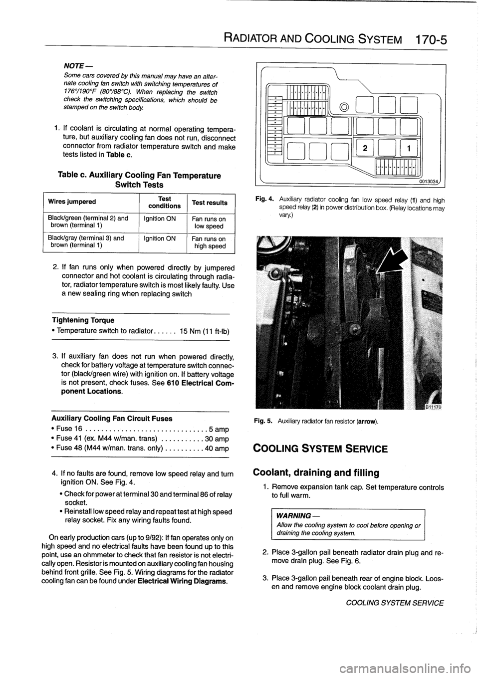
Fig
.
4
.
Auxiliary
radiator
cooling
fan
low
speed
relay
(1)
and
high
speed
relay
(2)
in
power
distribution
box
.
(Relay
locations
may
vary
.)
Auxiliary
Cooling
Fan
Circuit
Fuses
Fig
.
5
.
Auxiliary
radiator
fan
resistor
(arrow)
.
"
Fuse16
.
...................
..
..
...
...
.5
amp
"
Fuse
41
(ex
.
M44
w/man
.
trans)
.
..
.
..
.....
30
amp
"
Fuse
48
(M44
w/man
.
trans
.
only)
..
.
..
.....
40
amp
COOLING
SYSTEM
SERVICE
0013034
4
.
If
no
faults
are
found,
remove
low
speed
relay
and
turn
Coolant,draining
and
filling
ignition
ON
.
See
Fig
.
4
.
1
.
Remove
expansion
tank
cap
.
Set
temperature
controls
"
Check
for
power
at
terminal
30
and
terminal
86
of
relay
to
full
warm
.
socket
.
"
Reinstall
low
speed
relay
and
repeat
testat
high
speed
WARNING
-
relay
socket
.
Fix
any
wiring
faults
found
.
Allow
the
cooling
system
to
cool
before
openlng
or
On
early
productioncars
(up
to
9/92)
:
If
fan
operates
only
on
draining
the
cooling
system
.
high
speed
and
no
electrical
faults
have
been
foundup
to
this
point,
usean
ohmmeter
to
check
that
fan
resistor
is
not
electri-
2
.
Place
3
ra
allo
ug
.
beneath
radiator
drain
plug
and
re-
cally
open
.
Resistor
is
mounted
on
auxiliary
cooling
fan
housing
move
drain
plg
.
See
Fig
.
6
.
behind
front
grille
.
See
Fig
.
5
.
Wiring
diagrams
for
the
radiator
cooling
fan
canbefoundunder
Electrical
Wiring
Diagrams
.
3
.
Place
3-g
pail
beneath
rear
of
engine
blo
.
Loos-
en
and
re
mlon
ove
engine
blockcoolant
drain
plug
k
.
COOLING
SYSTEM
SERVICE
Page 387 of 759
610
Electrical
Component
Locations
GENERAL
...........
.
.
.
.
.
.
.
.
.
........
610-1
FOSE
POSITION
TABLES
..
.
.
.
.
.
.....
.
610-19
FUSE
AND
RELAY
POSITIONS
.
...
.
.
.
.
.
610-1
Fuse
Positions
.
.
.
................
.
.
.
.
.
610-1
Relay
Positions
.
.
.
.....
.
.
.
........
.
.
.
.
.
610-2
Auxiliary
RelayPanel
.....
.
...
.
........
.
610-2
SplicePanel,
Left
.
.
.
...
.
.
.
...
.
........
.
610-2
SplicePanel,
Right
.
.
.
.
.
.
.
.
...
.
.........
610-3
COMPONENT
LOCATIONS
.
.
.
.
.......
.
.610-3
Component
Location
Table
.
.
.
.
.
.
.........
610-9
GENERAL
FUSE
AND
RELAY
POSITIONS
This
repair
group
covers
f
use,
relay,
and
control
module
lo-
The
front
power
distribution
box,
an
auxiliary
relay
panel,cation
information
.
Electrical
equipment
and
accessories
in-
and
two
auxiliary
splice
panels
contain
most
of
the
fuses
and
stalled
varies
depending
on
model
and
model
year
.
Always
relays
in
E36
vehicles
.
Refer
to
the
component
location
later
confirm
that
the
proper
electrical
component
has
been
identi-
in
this
section,
as
well
as
the
tables
at
the
end
of
this
repair
fied
by
using
the
electrical
wiring
diagrams
.
group
for
electrical
component
location
.
WARNING
-
On
cars
equipped
with
airbags,
special
precautionsapply
to
any
electrical
system
testing
orrepair
.
Air-
bag
units
areexplosive
devices
and
mustbe
han-
dled
with
extremecare
.
Before
starting
any
work
onan
airbag
equipped
car,
refer
to
the
wamings
and
cautions
in
721
Airbag
System
(SRS)
.
CAUTION
-
"
Prior
to
disconnectiog
the
battery,
read
the
bat-
tery
disconnection
cautions
given
at
the
front
of
this
manual
on
page
viii
.
"
Relay
and
fuse
positions
are
subject
to
changeand
may
varyfrom
car
to
car
.
If
questions
arise,
an
authorized
BMW
dealer
is
the
best
source
for
the
most
accurate
and
up-to-date
information
.
"
A
good
way
to
verify
a
relay
position
isto
com-
pare
the
wiring
colors
at
the
relay
socket
to
thecolors
indicated
on
the
wiring
diagrams
located
at
the
rear
of
this
manual
.
"
Always
switchthe
ignition
off
and
disconnect
the
negative
(-)
battery
cable
before
removing
any
electrical
components
.
"
Connect
and
disconnect
ignition
system
wires,
multiple
connectors,
and
ignition
test
equipment
leads
only
while
the
ignition
is
switched
off
.
"
Only
usea
digital
multimeter
for
electrical
tests
.
ELECTRICAL
COMPONENT
LOCATIONS
610-1
TABLES
a
.
E36Component
Locations
...........
.
.
..
...
610-10b
.
1992
E36
Fuse
Positions
..........
..
.
.
.....
610-20c
.
1993
E36
Fuse
Positions
..........
..
..
.
....
610-22d
.
1994
E36
Fuse
Positions
.........
...
.......
610-24e
.
1995
E36
Fuse
Positions
.........
...
.......
610-26
f
.
1996
E36
Fuse
Positions
.........
...
.......
610-28g
.
1997-1998
E36
Fuse
Positions
..
.
..
...
.......
610-30
Fuse
Positions
CAUTION
-
"
Replace
fuses
with
those
of
the
same
rating
.
In-
stalling
a
fuse
with
higher
rating
can
lead
to
cir-
cuit
failure
and
may
also
start
a
fire
.
"
Relay/fuse
positions
vary
by
model
and
equip-
ment
.
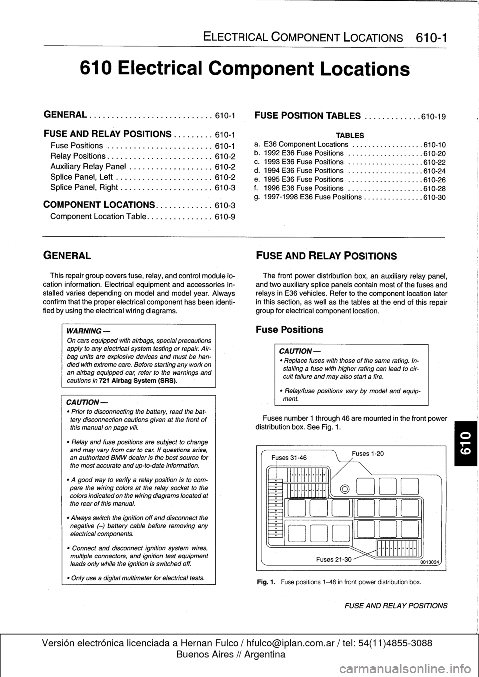
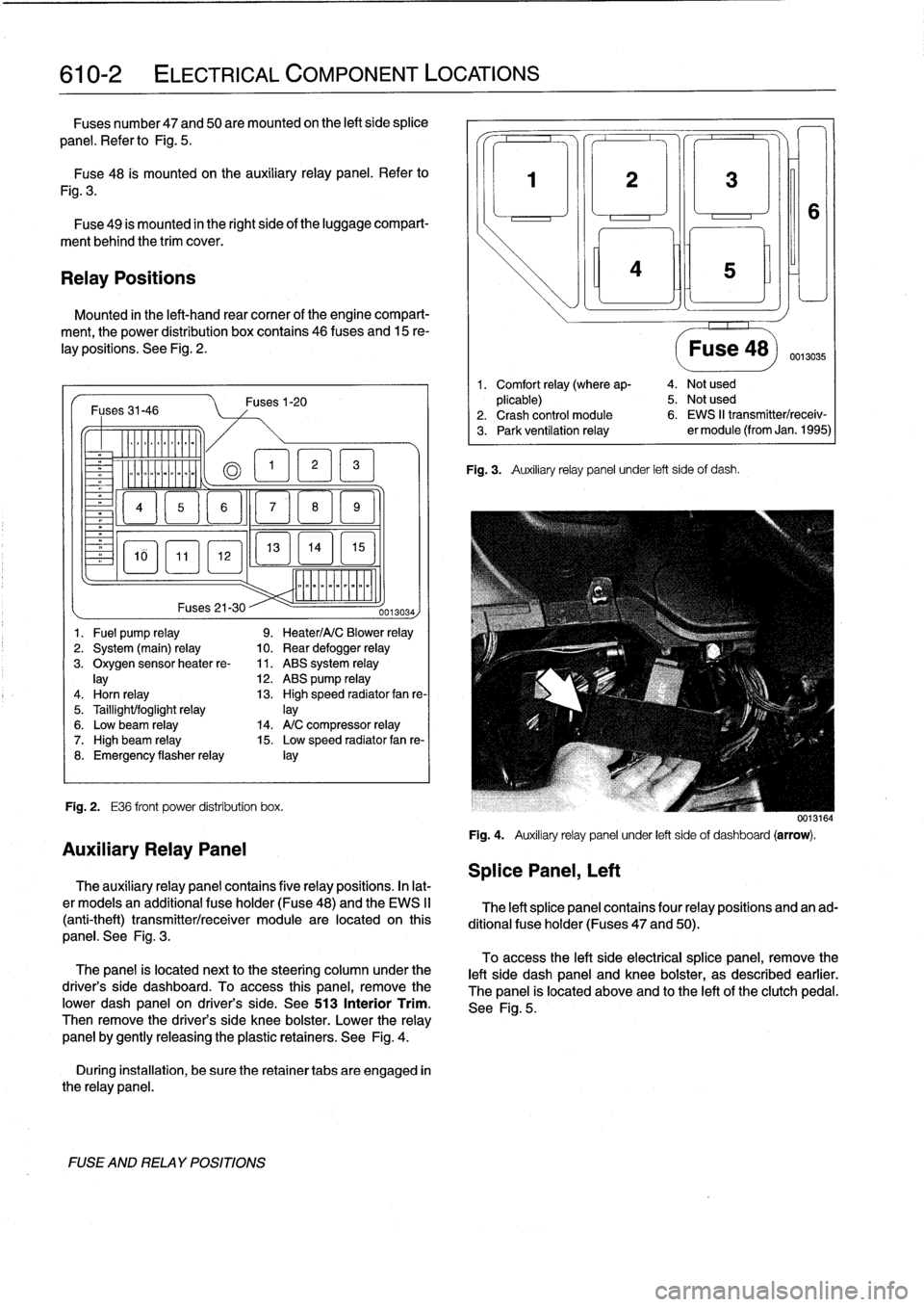
Fuses
number
1
through
46
are
mounted
in
the
front
power
distribution
box
.
See
Fig
.
1.
Fuses
31-46
~
Illlllllllll
°
-
Ilmmlmomlmoi
Fuses
1-20
(a
1
:1
E
El
~
~O!7
L~~n
4~
i
Fuses
21-30
Fig
.1.
Fuse
positions
1-46
in
front
power
distribution
box
.
0013034
FUSE
AND
RELAY
POSITIONS
Page 388 of 759
610-2
ELECTRICAL
COMPONENT
LOCATIONS
Fuses
number47
and
50are
mounted
on
the
left
side
splice
panel
.
Refer
lo
Fig
.
5
.
Fuse48
is
mounted
on
the
auxiliary
relay
panel
.
Refer
to
Fig
.
3
.
Fuse
49
is
mounted
in
the
right
side
of
the
luggage
compart-
ment
behind
the
trim
cover
.
Relay
Positions
Mounted
in
the
left-hand
rear
comer
of
the
engine
compart-
ment,
the
power
distribution
box
contains
46
(uses
and
15
re-
lay
positions
.
See
Fig
.
2
.
Fuses31-46
-
Er
a
&QT
MM
~
Fig
.
2
.
E36
front
power
distribution
box
.
FUSE
AND
RELAY
POSITIONS
Fuses1-20
13
EL1
5
]
mmmmmmmmmm
Fuses
21-30
--
0013034)
1
.
Fuel
pump
relay
9
.
Heater/A/C
Blower
relay
2
.
System
(main)
relay
10
.
Rear
defogger
relay
3
.
Oxygen
sensorheater
re-
11
.
ABS
system
relay
lay
12
.
ABS
pump
relay
4
.
Horn
relay
13
.
High
speed
radiator
fan
re-
5
.
Taillight/foglight
relay
]ay
6
.
Low
beam
relay
14
.
A/C
compressor
relay
7
.
High
beam
relay
15
.
Low
speed
radiator
fan
re-
8
.
Emergency
flasherrelay
¡ay
Auxiliary
Relay
Panel
The
auxiliary
relay
panel
contains
five
relay
positions
.
In
lat-
er
modeis
an
additional
fuse
holder
(Fuse48)
and
the
EWS
II
(anti-theft)
transmitter/receiver
module
are
located
on
this
panel
.
See
Fig
.
3
.
The
panel
is
located
nextto
the
steering
column
under
the
driver's
side
dashboard
.
To
access
this
panel,
remove
the
pwer
dash
panel
on
driver's
side
.
See513
Interior
Trim
.
Then
remove
the
driver's
side
knee
bolster
.
Lower
the
relay
panel
by
gently
releasing
the
plastic
retainers
.
See
Fig
.
4
.
During
installation,
be
sure
the
retainer
tabs
are
engaged
in
the
relay
panel
.
Splice
Panel,
Left
3
¡ni
Fig
.
3
.
Auxiliary
relay
panel
under
left
side
of
dash
.
Fuse
48)
0013035
1
.
Comfort
relay
(where
ap-
4
.
Not
used
plicable)
5
.
Not
used
2
.
Crash
control
module
6
.
EWS
II
transmitter/receiv-
3
.
Park
ventilation
relay
er
module
(from
Jan
.
1995)
0013164
Fig
.
4
.
Auxiliary
relay
panel
under
left
sideof
dashboard
(arrow)
.
The
left
splice
panel
contains
four
relay
positions
and
an
ad-
ditional
fuse
holder
(Fuses
47
and
50)
.
To
access
the
left
side
electrical
splice
panel,
remove
the
left
side
dash
panel
and
knee
bolster,
as
described
earlier
.
The
panel
is
located
above
and
lo
the
left
of
the
clutch
pedal
.
See
Fig
.
5
.
Page 390 of 759
610-4
ELECTRICAL
COMPONENT
LOCATIONS
--J
L
Windshield
washertank
&
pump
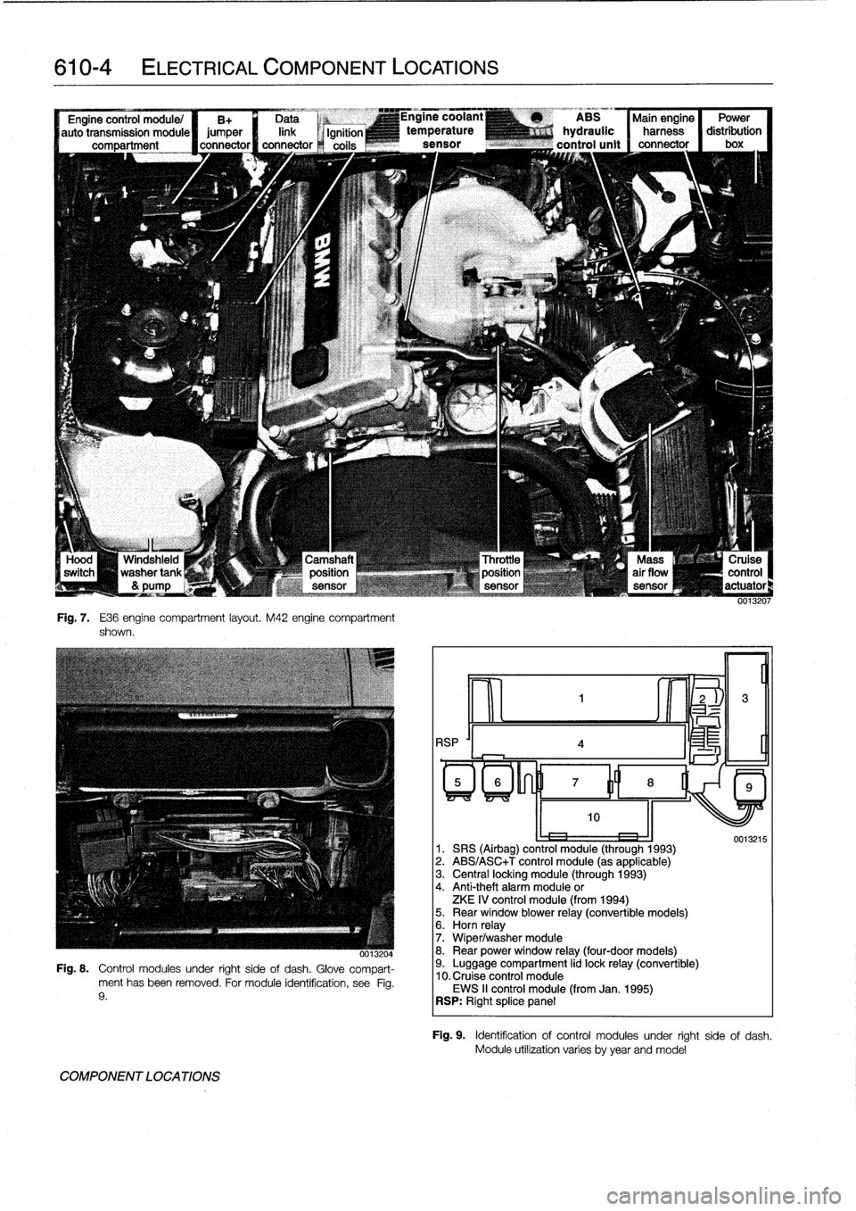
Fig
.
7
.
E36
engine
compartment
layout
.
M42
engine
compartment
shown
.
-,x
0013204
Fig
.
8
.
Control
modules
under
right
sideof
dash
.
Glove
compart-
ment
has
been
removed
.
For
module
identification,
see
Fig
.
9
.
COMPONENT
LOCATIONS
RSP
'I
4
ABS
Main
engine
Power
hydraulic
harness
distribution
control
unit
connector
I
box
oe
1
.
SRS
(Airbag)
control
module
(through
1993)
2
.
ABS/ASC+T
control
module
(as
applicable)
3
.
Central
locking
module
(through
1993)
4
.
Anti-theft
alarm
module
or
ZKE
IV
control
module
(from
1994)5
.
Rear
window
blower
relay
(convertible
models)6
.
Horn
relay
7
.
Wiper/washer
module
8
.
Rear
power
window
relay
(four-door
models)9
.
Luggage
compartment
lid
lock
relay
(convertible)
10
.
Cruise
control
module
EWS
II
control
module
(from
Jan
.
1995)
RSP
:
Right
splice
panel
0013215
Fig
.
9
.
Identificationof
control
modules
under
right
side
of
dash
.
Module
utilízation
varies
byyear
andmodel
Page 391 of 759
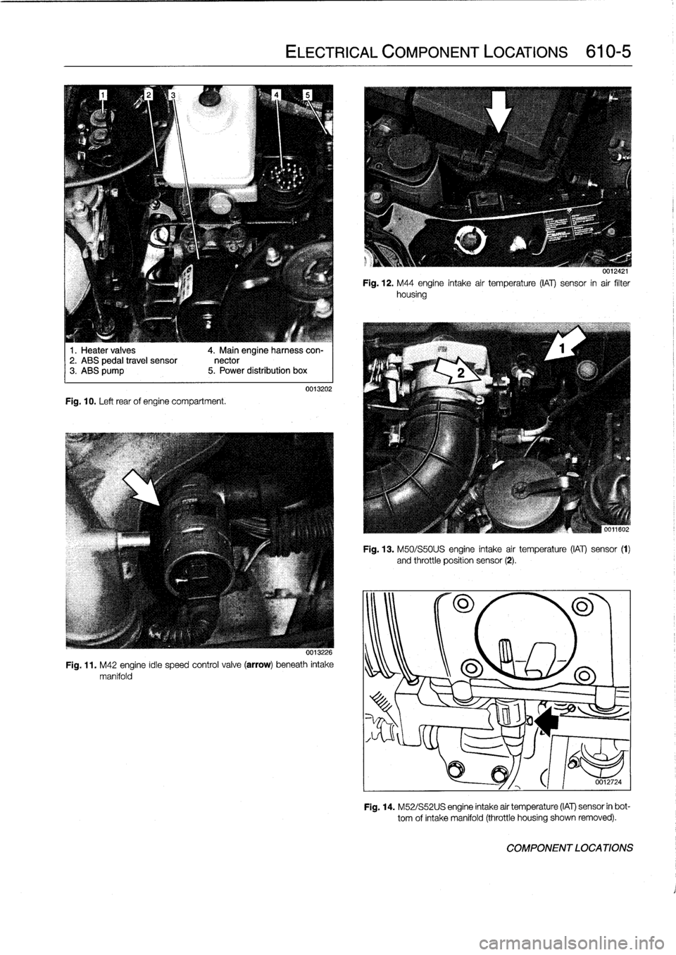
1
.
Heater
valves
2
.
ABS
pedal
travel
sensor3
.
ABS
pump
Fig
.
10
.
Left
rear
of
engine
compartment
.
4
.
Main
engineharness
con-
nector
5
.
Power
distribution
box
ELECTRICAL
COMPONENT
LOCATIONS
610-5
0013202
0013226
Fig
.
11
.
M42
engine
idie
speed
control
valve
(arrow)
beneath
intake
manifold
0012421
Fig
.
12
.
M44
engine
intake
air
temperature
(¡Al)
sensor
in
air
filter
housing
Fig
.
13
.
M50/S50U
S
engine
intake
air
temperature
(IAT)
sensor
(1)
and
throttle
position
sensor
(2)
.
301180
0012724
Fig
.
14
.
M52/S52U
S
engine
intake
air
temperature
(IAT)
sensor
in
bot-
tom
of
intake
manifold
(throttle
housing
shown
removed)
.
COMPONENT
LOCATIONS
Page 396 of 759
610-10
ELECTRICAL
COMPONENT
LOCATIONS
Component
Model
Year
Location
Refer
to
ABS
Hydraulic
Control
Unit
1992-1998
Left
rear
engine
compartment
undermaster
cylinder
Fig
.
7
.
Fig
.
10
.
ABS
Hydraulic
Control
Unit
Relay
1992-1998
Power
distribution
box
Fig
.
2
.
ABS
Pedal
Travel
Sensor
1992-1998
On
brake
booster
beside
master
cylinder
Fig
.
10
.
ABS
Relay
1992-1998
Power
distribution
box
Fig
.
2
.
ABS/AS
T
(Traction)
Control
Module
1992-1998
Behind
glove
compartment
Fig
.
8
.
Fig
.
9
.
ABS
Speed
Sensor,
Left
Front
1992-1998
Left
front
steering
arm
Fig
.
31
.
Wheel
ABS
Speed
Sensor,
Left
Rear
1992-1998
Left
rear
trailing
arm
Wheel
ABS
Speed
Sensor,
RightFront
11992-1998
Right
front
steering
arm
Wheel
ABS
Speed
Sensor,
Right
Rear
1992-1998
I
Left
rear
trailing
arm
Wheel
1
A/C
Compressor
1
1992-1998
(
Rightlower
frontof
engine
A/C
Compressor
Control
Relay
1
1992-1998
1992-1998
1992-1998
A/C
Control
Module
A/C
Evaporator
Temperature
Sensor
A/C
Pressure
Switch
1992-1998
Right
frontof
engine
compartment
A/C
Program
Switch
1992-1998
Center
of
dash
below
radio
A/CRecharging
Ports
1992-1998
Right
rear
engine
compartment
Fig
.
16
.
Air
Flow
Sensor
1992-1998
Between
throttle
housing
&
filter
housing
Fig
.
7
.
Airbag
Contact
Slip
Ring
1992-1998
Rear
ofsteering
wheel
Airbag,
Driver
1992-1998
In
center
of
steering
wheel
Fig
.
25
.
Airbag,
Passenger
1994-1998
Right
front
of
dash
above
glove
compartment
Fig
.
26
.
Airbag,
Side-Impact
1997-1998
Behind
right/left
front
door
panel
Airbag
Control
Module
(Basic)
1992-1993
Behind
glove
compartment
Fig
.
8
.
Fig
.
9
.
Airbag
Control
Module
(ZAE)
1994-1998
On
center
tunnel
under
rear
seat
cushion
Airbag
Crash
Sensor,
Airbag
1992-1993
On
righUleft
front
strut
tower
Airbag
Crash
Sensor,
Right/Left
1997-1998
Right/left
door
si¡¡
behind
front
seatSide
Impact
Alternator
(Generator)
1992-1998
Left
lowerfront
of
engine
Amplifier
Hi-fi
1992-1998
Left
front
side
of
luggage
compartment
Antenna
Amplifier
AM/FM
1992-1998
In
upper
left
side
C-pillar
Fig
.
27
.
COMPONENT
LOCA
TIONS
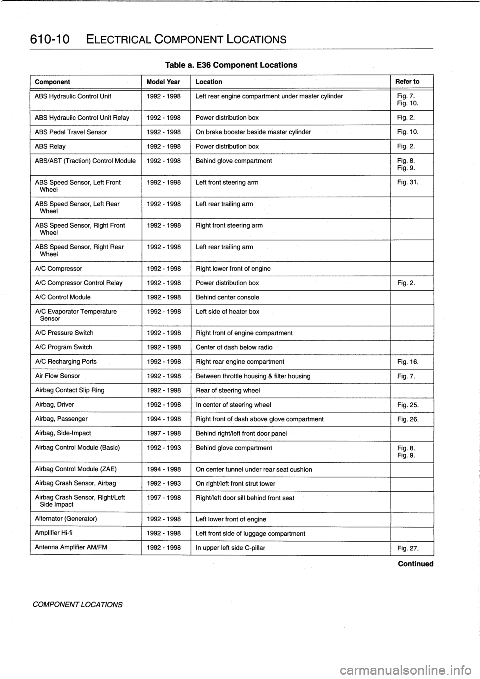
Table
a
.
E36
Component
Locations
Power
distribution
box
Fig
.
2
.
Behind
center
console
Left
sideof
heater
box
Continued
Page 397 of 759
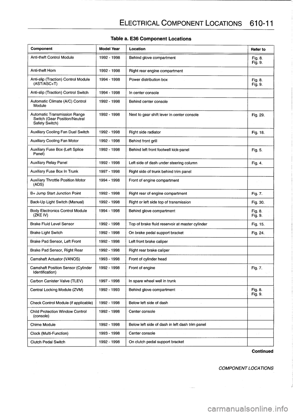
Table
a
.
E36
Component
Locations
Component
Model
Year
Location
Refer
to
Anti-theft
Control
Module
1992-1998
Behind
glove
compartment
Fig
.
8
.
Fig
.
9
.
Anti-theft
Horn
1
1992-1998
1
Right
rear
engine
compartment
Anti-slip
(Traction)
Control
Module
1994-1998
Power
distribution
box
Fig
.
8
.
(AST/ASC+T)
Fig
.
9
.
Anti-slip
(Traction)
Control
Switch
1994-1998
In
center
console
Automatic
Climate
(A/C)
Control
1992-1998
Behind
center
console
Module
AutomaticTransmission
Range
1992-1998
~
Next
to
gear
shift
lever
in
center
console
Fig
.
29
.
Switch
(Gear
Position/Neutral
Safety
Switch)
Auxiliary
Cooling
Fan
Dual
Switch
1992-1998
Right
side
radiator
1
Fig
.
18
.
Auxiliary
Cooling
Fan
Motor
1992-1998
Behind
front
grill
Auxiliary
Fuse
Box
(Left
Splice
1992-1998
I
Behind
left
front
footwell
kick-panel
Panel)
Auxiliary
RelayPanel
1
1992-1998
1
Left
side
of
dash
under
steering
column
Auxiliary
Fuse
Box
In
Trunk
1
1997-1998
1
Right
sideof
trunk
behind
trim
panel
AuADSry
ThrottlePosition
Motor
11994-1998
Front
of
engine
compartment
B+
Jump
Start
Junction
Point
1992-1998
Right
rear
of
engine
compartment
Fig
.
7
.
Back-Up
Light
Switch
(Manual)
1992-1998
Right
or
left
side
top
of
transmission
Fig
.
30
.
Body
Electronics
Control
Module
1994-1998
Behindglove
compartment
Fig
.
8
.
(ZKE
IV)
Fig
.
9
.
Brake
Fluid
Level
Sensor
1992-1998
Top
of
brake
fluid
reservoir
at
master
cylinder
Fig
.
15
.
Brake
Light
Switch
1
1992-1998
1
On
brake
pedal
supportbracket
Brake
Pad
Sensor,
Left
Front
1
1992-1998
1
Left
front
brake
caliper
Brake
Pad
Sensor,
Right
Rear
1992-1998
Right
rear
brake
caliper
Camshaft
Actuator
(VANOS)
1993-1998
Front
of
cylinder
head
Camshaft
Position
Sensor
(Cylinder
1992-1998
Front
of
engine
Identification)
Carbon
Canister
Valve
(TLEV)
1
1997-1998
1
In
sparewheel
well
in
trunk
ELECTRICAL
COMPONENT
LOCATIONS
610-11
Fig
.
5
.
Fig
.
4
.
Fig
.
24
.
Fig
.
7
.
Central
Locking
Module
(ZVM)
11992-1993
1
Behindglove
compartment
I
Fig
.
8
.
Fig
.
9
.
Check
Control
Module
(if
applicable)
1
1992
-
1998
1
Below
left
side
of
dash
Child
Protection
Window
Control
1992-1998
Center
console
(console)
Chime
Module
1992-1998
Below
left
side
of
dash
inleft
dash
trim
panel
Clock
(Multi-Function)
1993-1998
Center
console
Clutch
Pedal
Switch
1992-1998
On
clutch
pedal
support
bracket
Continued
COMPONENT
LOCATIONS
Page 399 of 759
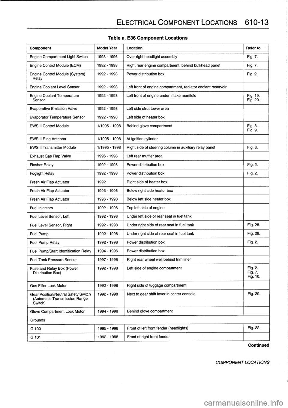
Tablea
.
E36
Component
Locations
Component
Model
Year
Location
Refer
to
Engine
Compartment
Light
Switch
1993-1996
Over
right
headlight
assembly
Fig
.
7
.
Engine
Control
Module
(ECM)
1992-1998
Right
rear
enginecompartment,
behind
bulkhead
panel
Fig
.
7
.
Engine
Control
Module
(System)
1992-1998
I
Power
distribution
box
Fig
.
2
.
Relay
Engine
Coolant
Leve¡
Sensor
1
1992-1998
1
Left
front
of
enginecompartment,
radiator
coolant
reservoir
Engine
Coolant
Temperature
1992-1998
I
Left
front
of
engine
under
intake
manifold
I
Fig
.
19
.
Sensor
Fig
.
20
.
Evaporative
Emission
Valve
1992-1998
Left
side
strut
Power
area
Evaporator
Temperature
Sensor
1992-1998
Left
side
of
heater
box
EWS
II
Control
Module
1/1995
-
1998
Behind
glove
compartment
Fig
.
8
.
Fig
.
9
.
EWS
II
Ring
Antenna
1
1/1995
-
1998
1
At
ignition
cylinder
EWS
II
Transmitter
Module
1/1995
-
1998
Right
side
of
steering
column
in
auxiliaryrelay
panel
Fig
.
3
.
Exhaust
Gas
Flap
Valve
1996-1998
Left
rear
muffler
area
Flasher
Relay
1992-1998
Power
distribution
box
Fig
.
2
.
Foglight
Relay
1
1992-1998
1
Power
distribution
box
1
Fig
.
2
.
Fresh
Air
FlapActuator
1
1992
1
Right
side
of
heater
box
Fresh
Air
FlapActuator
1
1993-1995
1
Below
right
side
heater
box
Fresh
Air
FlapActuator
1
1996-1998
Below
left
side
heater
box
Fuel
Injectors
1992
-
1998
Top
left
side
of
engine
Fuel
Leve¡
Sensor,
Left
1
1992-1998
/
Under
left
side
of
rear
seat
infuel
tank
Fuel
Leve¡
Sensor,
Right
1
1992-1998
1
Under
right
side
of
rear
seat
in
fuel
tank
1
Fig
.
28
.
Fuel
Pump
1
1992-1998
1
Under
right
side
of
rear
seat
in
fuel
tank
1
Fig
.
28
.
Fuel
Pump
Relay
1
1992-1998
1
Power
distribution
box
1
Fig
.
2
.
Fuel
Pump/Start
Identification
Relay
1994
-
1996
Power
distribution
box
Fuel
Tank
Pressure
Sensor
1
1997-1998
1
Right
rear
wheel
well
behind
trim
liner
ELECTRICAL
COMPONENT
LOCATIONS
610-13
Fuse
andRelay
x(Power
11992-1998
I
Left
side
of
engine
compartment
I
Fig
.
2
.
Distribution
Box
Fig
.
7
Fig
.
10
.
Gas
Filler
LockMotor
1992-1998
Right
side
of
luggage
compartment
Gear
Position/Neutral
Safety
Switch
1992-1998
Next
to
gear
shift
lever
in
center
console
Fig
.
29
.
(Automatic
Transmission
Range
Switch)
Glove
Compartment
Lock
Motor
1994-1998
Behind
glove
compartment
Grounds
G
100
1995-1998
Front
of
left
front
fender
(headlights)
Fig
.
22
.
G
101
1992-1998
Front
of
right
front
fender
Continued
COMPONENT
LOCATIONS