starter relay BMW 323i 1998 E36 Workshop Manual
[x] Cancel search | Manufacturer: BMW, Model Year: 1998, Model line: 323i, Model: BMW 323i 1998 E36Pages: 759
Page 48 of 759

100-6
ENGINE-GENERAL
Cylinder
compression,
checking
A
compression
tester
is
needed
to
make
a
compression
test
.
To
obtain
accurate
test
results,
the
battery
and
starter
must
be
capable
of
cranking
the
engine
at
250-300
rpm,
and
theen-
gine
should
be
at
normal
operating
temperature
.
Use
com-
pressed
air
to
clean
aroundthe
spark
plugs
before
removal
.
1
.
Disable
the
ignítion
system
by
removing
the
engine
management
system
main
relay
and
the
fuel
pump
re-
¡ay
.
See
Fig
.
6
.
WARNING
-
The
ignítion
system
produces
high
voltages
that
canbe
fatal
.
Avoid
contact
with
exposed
termínals
and
useextreme
caution
when
working
on
acar
wíth
the
ignítion
switched
on
or
the
engine
running
.
Fuel
DM
E
pump
main
re
ay
rel
ay
o
oa
ooa
.,
o00
oao
Fig
.
6
.
Engine
management
relays
in
power
distribution
box
inleft
rear
of
engine
compartment
.
CAUTION-
"
On
OBD
11
cars,
making
a
compression
test
may
causea
faultto
set
in
the
ECM
and
may
also
il-
luminate
the
Check
Engine
light
.
The
light
can
only
be
tumed
out
using
special
scan
tool
equip-
ment,using
eíther
the
BMW
specialservíce
tool
or
using
a
"generic"
OBD
11
scan
tool
.
Discon-
necting
the
battery
will
not
erase
the
fault
mem-
orynor
turn
outthe
light
.
0013034,
0012630
Fig
.
7
.
Remove
spark
plug
wires
from
spark
plugs
on
4-cylinder
en-
gine
using
special
tool
.
Tool
is
stored
under
cover
at
rear
of
cylinder
head
(arrow)
.
Fig
.
8
.
Remove
engine
cover
on
6-cylinder
engine
byprying
off
nut
covers
and
removing
nuts
(A)
.
Be
careful
not
to
let
rubber
in-
sulators
fall
off
as
cover
is
removed
(arrows)
.
4
.
On
6-cylinder
engines,
disconnect
the
harness
connec-
tors
from
the
ignítion
coils
by
lifting
the
retaining
clip
.
Remove
the
coil
mounting
nuts
andremove
the
six
coils
.
See
Fig
.
9
.
Remove
the
sparkplugs
.
"
Failure
to
remove
the
main
relay
or
attempting
to
disable
the
ignítion
system
by
other
methods
may
resultin
damage
to
the
engine
control
module
.
NOTE-
Used
sparkplugs
should
be
reinstalled
in
the
same
cyl-
2
.
On
4-cylinder
engine
:
Remove
plastic
engine
cover
from
inder
fromwhich
they
were
removed
.
top
of
cylinder
head
.
Disconnect
spark
plug
wires
and
re-
move
spark
plugs
.
See
Fig
.
7
.
5
.
Insta¡¡
the
compression
gauge
in
the
first
cylinder's
3
.
On
6-cylinder
engine
:
Remove
top
engine
coverby
pry-
spark
plug
hole,
tight
enough
to
form
a
good
seal
.
ing
off
nut
covers
and
removing
mounting
nuts
.
See
Fig
.
8
.
MECHANICAL
TROUBLESHOOTING
Page 126 of 759
120-2
IGNITION
SYSTEM
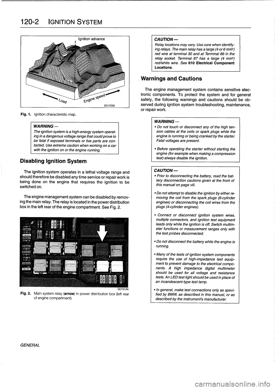
Fig
.1
.
Ignition
characteristic
map
.
Disabling
Ignition
System
WARNING
-
The
ignition
system
is
a
high-energy
system
operat-
ing
in
a
dangerous
voltage
range
that
couldprove
to
be
fatal
if
exposed
terminals
or
live
parts
are
con-
tacted
.
Use
extreme
caution
when
working
on
a
car
with
the
ignition
on
or
the
engine
running
.
The
ignition
system
operates
in
a
lethal
voltage
range
and
should
therefore
be
disabied
any
time
senrice
or
repair
work
is
being
doneon
the
engine
that
requires
the
ignition
to
be
switched
on
.
The
engine
management
system
can
be
disabled
byremov-
ingthe
main
relay
.
The
relay
is
located
in
the
power
distribution
box
in
the
left
rear
of
the
engine
compartment
.
See
Fig
.
2
.
0013134
Fig
.
2
.
Maínsystem
relay
(arrow)
in
power
distribution
box
(left
rear
of
engine
compartment)
.
GENERAL
WARNING
-
"
Do
not
touch
or
disconnect
any
of
the
high
ten-
sion
cables
at
the
cotls
orspark
plugs
while
the
engine
ts
running
orbeingcranked
by
the
starter
.
Fatalvoltages
are
present
.
"
Before
operating
the
starter
without
starting
the
engine
(for
example
when
making
a
compression
test)
always
disable
the
ignition
.
CAUTION-
"
Prior
to
disconnecting
the
battery,
read
the
bat-tery
disconnection
cautions
gtven
at
the
front
of
thts
manual
on
page
viti
.
"
Do
not
attempt
to
disable
the
ignition
by
either
re-
moving
the
cotl
from
the
spark
plugs
(6-cylinder
engines)
or
disconnecting
the
coll
wires
from
the
plugs
(4-cylinder
engines)
.
"
Connect
or
disconnect
ignition
system
wires,
multiple
connectors,
and
ignition
test
equipment
leads
only
while
the
ignitionis
off
.
Switch
multtm-
eter
functions
or
measurement
ranges
onty
with
the
test
probes
disconnected
.
"
Do
not
disconnect
the
battery
while
the
engine
ts
running
.
"
Many
of
the
tests
of
ignition
system
components
require
the
use
of
high-impedance
test
equip-
ment
to
prevent
damage
to
the
electrical
compo-
nents
.
A
high
impedance
digital
multimeter
should
be
used
for
all
voltage
and
resistance
tests
.
AnLED
test
light
shouldbe
used
in
place
of
an
incandescent-type
test
lamp
.
"In
general,
make
test
connections
only
as
speci-fied
by
BMW,
as
described
inthis
manual,
or
as
described
by
the
instrumenta
manufacturer
.
Page 143 of 759
Alternator
brushes,
STARTER
SERVICE
inspecting
and
replacing
Regulator
brushesarenot
available
as
replacement
parts
from
BMW
.
Replacement
brushes
may
be
available
from
af-
termarket
sources,
however
.
1
.
Remove
voltage
regulator
as
described
above
.
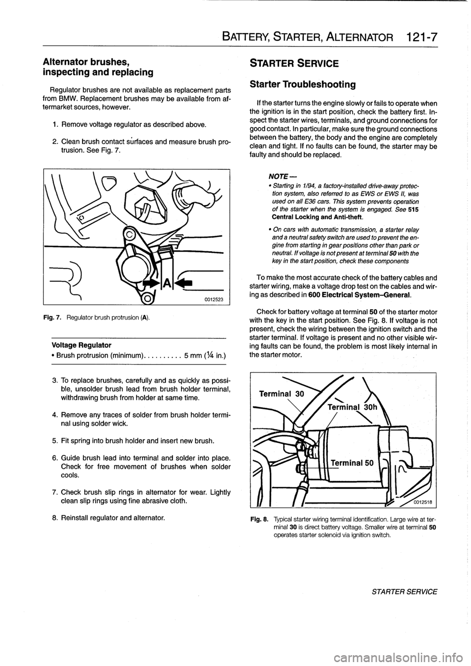
2
.
Clean
brush
contact
sürfaces
and
measure
brush
pro-trusion
.
See
Fig
.
7
.
Check
for
battery
voltage
at
terminal
50
of
the
starter
motor
Fig
.
7
.
Regulator
brush
protrusion
(A)
.
with
the
key
in
the
start
position
.
See
Fig
.
8
.
If
voltage
is
not
present,
check
the
wiring
between
the
ignition
switch
and
the
starter
terminal
.
If
voltage
is
present
and
no
other
visible
wir
Voltage
Regulator
ing
faults
can
be
found,
the
problem
is
most
likely
interna¡in
"
Brush
protrusion
(minimum)
.......
.
..
5
mm
(
1
/4
in
.)
the
starter
motor
.
3
.
To
replace
brushes,
carefully
and
as
quickly
as
possi-
ble,
unsolder
brush
lead
from
brush
holder
termina¡,
withdrawing
brush
from
holder
at
same
time
.
4
.
Remove
any
traces
of
solder
frombrush
holder
termi-
nal
using
solder
wick
.
5
.
Fit
spring
into
brush
holder
and
inserí
new
brush
.
6
.
Guide
brush
lead
into
terminal
and
solder
into
place
.
Check
for
free
movement
of
brushes
when
solder
cools
.
7
.
Check
brush
slip
rings
in
alternator
for
wear
.
Lightly
clean
slip
rings
using
fine
abrasive
cloth
.
BATTERY,
STARTER,
ALTERNATOR
121-
7
Starter
Troubleshooting
If
the
starter
tucos
the
engine
slowlyor
fails
to
operate
when
the
ignition
isin
the
start
position,
check
the
battery
first
.
In-
spect
the
starter
wires,
terminals,
and
ground
connections
for
good
contact
.
In
particular,
make
sure
the
ground
connections
between
the
battery,
the
body
and
the
engine
are
completely
clean
and
tight
.
If
no
faults
can
be
found,
the
starter
may
be
faulty
and
should
be
replaced
.
NOTE
-
"
Starting
in1194,
a
factory-installed
drive-away
protec-
tion
system,
alsoreferred
to
as
EWS
or
EWS
11,
was
used
on
all
E36
cars
.
This
system
prevenís
operation
of
the
starter
when
the
system
is
engaged
.
See
515
Central
Locking
and
Anti-theft
.
"
On
cars
with
automatic
transmission,
a
starter
relay
and
a
neutral
safetyswitchare
used
to
present
theen-
ginefrom
starting
in
gear
positions
other
than
park
or
neutral
.
ff
voltage
is
not
present
atterminal
50
with
the
key
in
the
startposition,
check
these
components
To
make
the
most
accurate
check
of
the
battery
cables
and
starterwiring,
make
a
voltage
drop
test
on
the
cables
and
wir-
ing
as
described
in
600
Electrical
System-General
.
Terminal
30
'
\
/
Terminal
30h
0012518
8
.
Reinstall
regulator
and
alternator
.
Fig
.
8
.
Typical
starterwiring
terminal
identification
.
Large
wireat
ter-
minal
30
is
direct
battery
voltage
.
Smaller
wire
at
terminal
50
operates
starter
solenoid
via
ignition
switch
.
STARTER
SERVICE
Page 152 of 759
130-
6
FUEL
INJECTION
Warnings
and
Cautions
For
personal
safety,
as
well
as
the
protection
of
sensitive
electronic
components,
the
following
warnings
and
cautions
should
be
adhered
to
when
working
on
the
engine
manage-
ment
system
.
GENERAL
WARNING
-
"
The
ignition
system
produces
high
voltages
that
can
be
fatal
.
Avoid
contact
with
exposed
termi-
nals
.
Use
extreme
caution
when
working
onacar
with
the
ignition
switched
on
or
the
engine
run-
ning
.
"
Do
not
touch
or
disconnect
any
high
voltage
ca-
bles
from
the
coils
or
spark
plugs
while
the
engine
is
running
or
beingcranked
by
the
starter
.
"
Connect
and
disconnect
the
DME
system
wiring
and
test
equipment
leads
only
when
the
ignition
is
switched
off
.
"
Gasoline
is
highly
flammable
and
fts
vaporsare
explosive
.
Do
not
smoke
or
work
on
a
car
near
heaters
or
other
fire
hazards
when
diagnosing
and
repalring
fuel
system
problems
.
Have
a
tire
extinguisher
avaílable
in
case
of
an
emergency
.
"
When
working
onan
open
fuel
system,
wear
suit-
able
hand
protection,
asprolonged
contact
wfth
fuel
can
cause
illnesses
and
skin
disorders
.
"
Renew
fuel
system
hoses,
clamps
and
O-rings
any
timethey
are
removed
.
"
Before
makingany
electrical
tests
that
require
the
engine
to
be
cranked
using
the
starter,
disable
the
ignition
system
as
described
in
120
Ignition
System
.
CAUTION-
"
Prior
to
disconnecting
the
battery,
read
the
bat-
tery
disconnectinn
cautions
given
at
the
front
of
this
manual
onpage
vifi
.
"
Do
not
connect
any
test
equipment
that
delivers
a
12-volt
power
supply
to
terminal
15
(+)
of
the
ig-
nitioncoil
.
The
current
flow
may
damage
the
ECM
.
In
general,
connect
test
equipment
only
as
speclfied
by
BMW,
this
manual,
or
the
equipment
maker
.
"
Only
use
a
digital
multlmeter
for
electrical
test
.
"
Only
use
an
LED
test
light
for
quick
tests
.
"
Disconnecting
the
battery
may
erase
fault
code(s)
stored
in
memory
.
Check
for
fault
codes
prior
to
disconnecting
the
battery
cables
.
ff
the
Check
Engine
light
ís
illuminated,
see100En-
gine-General
for
DME
fault
code
information
.
ff
any
other
system
faults
have
been
detected
(indi-
catedbyan
illuminated
warning
light),
see
an
au-
thorized
BMW
dealer
.
Additional
systems
with
self-diagnostic
capabilities
include,
ABS
(Anti-
lock
brakes),
SRS
(Airbags),
EML
and
ASC+T
and
AST
(Traction
Control)
.
"
Do
not
run
the
engine
wfth
any
of
the
spark
plug
wires
dlsconnected
.
Catalytic
converter
damage
may
result
.
"
Always
waitat
least
40
seconds
afterturning
off
the
ignition
before
removing
the
engine
control
module
(ECM)
connector
.
ff
the
connector
isre-
moved
before
this
time,
residual
power
in
the
sys-
tem
relay
may
damage
the
control
module
.
"
Cleanliness
is
essential
when
working
onan
open
fuel
system
.
Thoroughly
clean
fuel
line
con-
nections
and
surroundlng
areas
before
loosen-
ing
.
Avoid
moving
the
car
.
Only
fnstall
cleanparts
.
"
Fuel
system
cleaners
and
other
chemical
addi-
tives
other
than
those
specifically
recommended
by
BMW
may
damage
the
catalytic
converter,
the
oxygensensor
or
other
fuel
supply
components
.
Page 157 of 759
3
.
Observe
fuel
pressure
gauge
after
20
minutes
.
The
pressure
shouldnot
drop
off
more
than
0
.5
bar
from
system
pressure
listed
in
Tablec
.
4
.
When
finished
testing,
disconnect
pressure
gauge
and
reconnect
fuel
line
.
If
the
fuel
system
does
not
maintain
pressure,
check
visual-
¡y
for
leaks
in
fuel
lines
orat
unions
.
Leaks
can
also
be
due
to
a
leaking
injector
or
a
faulty
fuel
pump
check
valve
.
Check
the
pump
check
valve
by
repeating
the
test,
butbefore
turning
the
fuel
pump
off,
pinch
off
theretum
line
at
the
fuel
rail
.
If
the
pressure
is
now
maintained,
the
fault
is
most
likely
the
fuel
pump
check
valva
.
Tabla
c
.
Fuel
Pressure
Specifications
Engine
1
Fuel
pressure
4-cytinder
1
3
.0
t
0
.2
bar
(43
.5
t
2
.9psi)
6-cytinder
M50/S50US
engine
3
.0
t
0
.2
bar
(43
.5
±2
.9psi)
M52/S52US
engine
3
.5
f
0
.2
bar
(51
t
2.9psi)
Fuel
pressure
regulator
response
to
engine
load,
testing
1
.
With
fuel
pressure
gauge
connected,
reinstallfuel
pump
relay
.
Start
engine
and
allow
it
to
idle
.
NOTE-
The
fuel
pressure
should
be
lower
by0
.4-0.7
bar
from
the
specifications
listed
in
Table
c
.
Engine
vacuum
act-
ing
on
the
fuel
pressure
regulator
diaphragm
reduces
the
fuel
pressure
.
2
.
With
engine
idling,
remove
vacuum
hose
from
regula-
tor
.
Pressure
should
increase
.
3
.
Reconnecthose
and
check
that
pressure
decreases
.
4
.
When
finished
testing,
disconnect
pressure
gauge
and
reconnect
fuelline
.
Tighten
hose
clamp
.
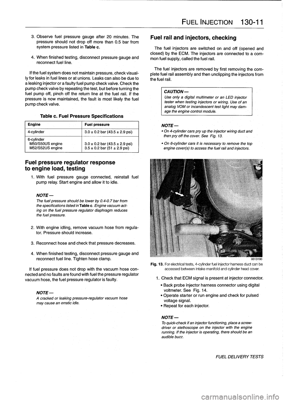
0013190
Fig
.
13
.
For
electrical
tests,
4-cytinder
fuel
injector
harnessduct
can
be
If
fuel
pressure
does
not
drop
with
the
vacuum
hose
con-
accessed
between
intake
manifold
and
cytinder
head
cover
.
nected
and
no
faulty
are
found
with
fuel
the
pressure
regulator
vacuum
hose,
the
fuel
pressure
regulator
is
faulty
.
1
.
Check
that
ECM
signal
is
present
atinjector
connector
.
NOTE-
A
cracked
or
leaktng
pressure-regulator
vacuum
hose
may
cause
en
erratic
tdle
.
FUEL
INJECTION
130-
11
Fuel
rail
and
injectors,
checking
The
fuel
injectors
are
switched
on
and
off
(opened
and
closed)
by
the
ECM
.
The
injectors
are
connected
to
a
com-
mon
fuel
supply,
callad
the
fuel
rail
.
The
fuel
injectors
are
removed
by
first
removing
the
com-
plete
fuel
rail
assembly
and
then
unclipping
the
injectors
from
the
fuel
rail
.
CA
UTION-
Use
only
a
digital
multimeter
or
an
LED
injector
tester
when
testing
injectors
or
wiring
.
Use
of
ananalog
VOM
or
incandescent
testlight
may
dam-
age
the
engine
control
module
.
NOTE-
"
On
4-cytindercars
pry
up
the
injector
wiring
duct
and
then
pry
off
the
cover
.
See
Fig
.
13
.
"
On
6-cytinder
cars
it
is
necessary
to
remove
the
top
engine
cover(s)
to
access
the
fuel
rail
and
injectors
.
"
Back
probe
injector
harness
connector
using
digital
voltmeter
.
See
Fig
.
14
.
"
Operate
starter
or
run
engine
and
check
for
pulsad
voltage
signal
.
"
Repeat
for
each
injector
.
NOTE
-
To
quick-check
if
en
injectorfunctioning,
place
a
screw-
driver
or
stethoscope
on
the
injector
with
the
engine
running
.
If
the
injector
is
operating,there
should
been
audible
buzz
.
FUEL
DELIVERYTESTS
Page 179 of 759
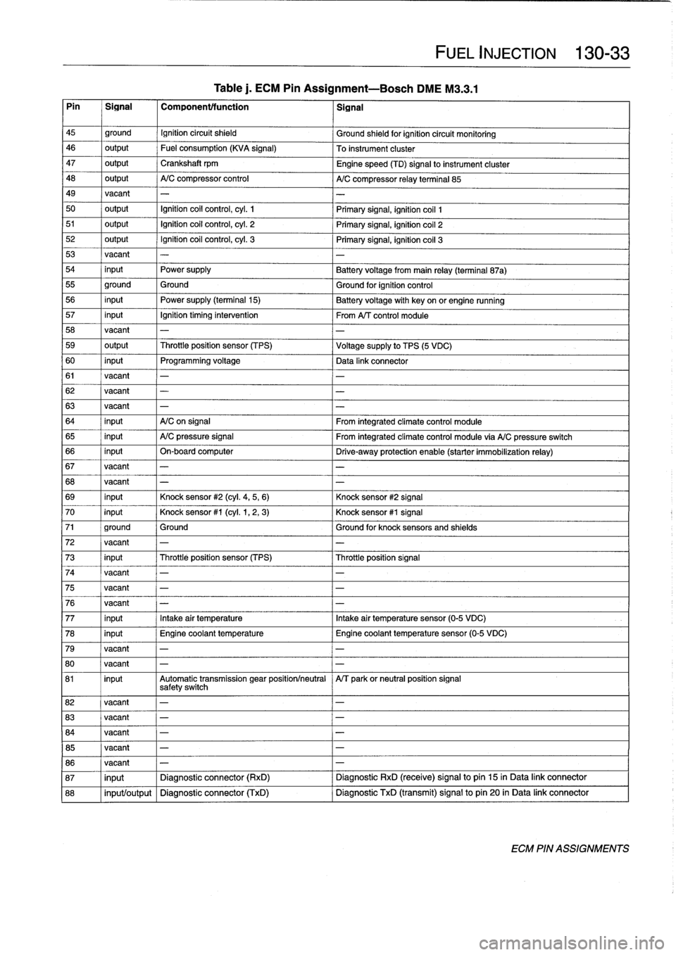
Table
j.
ECM
Pin
Assignment-Bosch
DME
M3
.3
.1
Pin
~
Signal
1
Componentffunction
1
signal
FUEL
INJECTION
130-
33
45
ground
Ignition
circuit
shield
Ground
shieldfor
ignition
circuit
monitoring
46
output
Fuel
consumption
(KVA
signal)
To
instrument
cluster
47
output
Crankshaft
rpm
Engine
speed
(TD)
signal
to
instrument
cluster
48
output
A/C
compressor
control
A/C
compressor
relay
terminal
85
49
vacant
-
-
50
output
Ignition
coil
control,
cyl
.
1
Primary
signal,
ignition
coil
1
51
output
Ignition
coil
control,
cyl
.
2
Primary
signal,
ignition
coil
2
52
output
Ignition
coil
control,
cyl
.
3
Primary
signal,
ignition
coil
3
53
vacant
-
-
54
input
Power
supply
Battery
voltagefrom
main
relay
(terminal
87a)
55
ground
Ground
Ground
for
ignition
control
56
input
Power
supply
(terminal15)
Batteryvoltage
with
key
on
or
engine
running
57
input
Ignition
timing
intervention
From
A/T
control
module
58
vacant
-
-
59
output
Throttleposition
sensor
(TPS)
Voltage
supply
to
TPS
(5
VDC)
60
input
Programming
voltage
Data
link
connector
61
vacant
-
-
62
vacant
-
-
63
vacant
-
-
64
input
A/C
on
signal
From
integrated
climate
control
module
65
input
A/C
pressure
signal
From
integrated
climate
control
module
via
A/C
pressure
switch
66
input
On-board
computer
Drive-away
protection
enable
(starter
immobilization
relay)
67
vacant
-
-
68
vacant
-
-
69
input
Knock
sensor
#2
(cyl
.
4,5,
6)
Knock
sensor
#2
signal
70
input
Knock
sensor
#1
(cyl
.
1,2,
3)
Knock
sensor
#1
signal
71
ground
Ground
Ground
for
knock
sensors
and
shields
72
vacant
-
-
73
input
Throttleposition
sensor
(TPS)
Throttleposition
signal
74
vacant
-
75
vacant
-
-
76
vacant
-
77
input
Intakeair
temperatura
Intakeair
temperatura
sensor
(0-5
VDC)
78
input
Engine
coolant
temperature
Engine
coolant
temperature
sensor
(0-5
VDC)
79
vacant
-
80
vacant
-
-
81
input
Automatic
transmission
gear
positionlneutral
A/T
parkor
neutral
position
signal
safetyswitch
82
vacant
-
-
83
vacant
-
-
84
vacant
-
-
85
vacant
-
-
86
vacant
-
-
87
input
Diagnostic
connector
(RxD)
Diagnostic
RxD
(receive)
signal
to
pin
15
in
Data
link
connector
88
input/output
Diagnostic
connector
(TxD)
Diagnostic
TxD
(transmit)
signal
to
pin
20
in
Data
link
connector
ECM
PIN
ASSIGNMENTS
Page 381 of 759
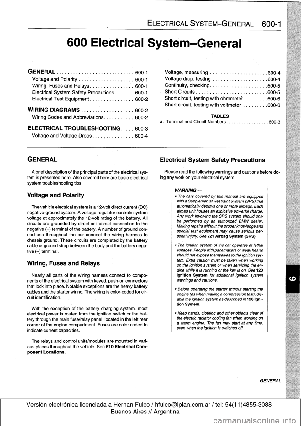
600
Electrical
System-General
GENERAL
.
...........
.
.
.
.
.
.
.
.
.
...
.
...
600-1
Voltage
and
Polarity
........
.
.
.
.
.
.
.
.....
600-1
Ming,
Fuses
and
Relays
............
.
.
.
.
600-1
Electrical
System
Safety
Precautions
...
.
.
.
.
600-1
Electrical
Test
Equipment
.....
.
.
.
....
.
.
.
.
600-2
WIRING
DIAGRAMS
..
.
.
.
.
.
.
.
.
.
........
600-2
Ming
Codes
and
Abbreviations
..
.
...
.
....
600-2
ELECTRICAL
TROUBLESHOOTING
..
.
..
600-3
Voltage
and
Voltage
Drops
..........
.
.
.
.
.
600-4
GENERAL
Electrical
System
Safety
Precautions
A
brief
description
of
the
principal
parts
of
the
electrical
sys-
tem
is
presented
here
.
Also
covered
here
are
basic
electrical
system
troubleshooting
tips
.
Voltage
and
Polarity
The
vehicle
electrical
system
is
a
12-volt
direct
current
(DC)
negative-ground
system
.
A
voltage
regulator
controls
system
voltage
at
approximately
the
12-volt
rating
of
the
battery
.
Al¡
circuits
are
grounded
by
direct
or
indirect
connection
to
the
negative
(-)
terminal
of
the
battery
.
A
number
of
ground
con-
nections
throughout
the
car
connect
the
wiring
harness
to
chassis
ground
.
These
circuits
are
completedby
the
battery
cable
or
ground
strap
between
the
body
and
the
battery
nega-
tive
(-)
terminal
.
Wiring,
Fuses
and
Relays
Nearly
all
parts
of
the
wiring
harnessconnect
to
compo-
nents
of
the
electrical
system
with
keyed,
push-on
connectors
that
lock
into
place
.
Notable
exceptions
arethe
heavy
battery
cables
and
the
starter
wiring
.
The
wiring
is
color-coded
for
cir-
cuitidentification
.
With
theexception
of
the
battery
charging
system,
most
electrical
power
is
routed
from
the
ignition
switch
or
the
bat-
tery
through
the
main
fuse/relay
panel,
located
in
¡he
left
rear
comer
of
the
engine
compartment
.
Fuses
are
color
coded
to
indicate
current
capacities
.
The
relays
and
control
units/modules
are
mounted
in
vari-
ous
places
throughout
the
vehicle
.
See610
Electrical
Com-
ponent
Locations
.
ELECTRICAL
SYSTEM-GENERAL
600-1
Voltage,
measuring
.
.
.
................
.
.
600-4
Voltage
drop,
testing
.
.
.....
.
.....
.
......
600-4
Continuity,
checking
..
.
...
.
.
.
.
.
.
.
.
.
.
.
.
.
.
.
600-5
Short
Circuits
.
.
.
.
.
.
.
.
.....
.
...
.
.
.
.
.
.
.
.
.
600-5
Short
circuit,
testing
with
ohmmete'r
.
.
.
.
.
.
.
.
.
600-6
Short
circuit,
testing
with
voitmeter
.
.
.
.
.
.
.
.
.
600-6
TABLES
a
.
Terminal
and
Circuit
Numbers
..............
..
.600-3
Please
read
the
following
warnings
and
cautions
before
do-
ing
any
work
on
your
electrical
system
.
WARNING
-
"
The
cars
covered
by
this
manual
are
equipped
with
aSupplemental
Restraint
System
(SRS)
that
automatically
deploys
one
or
more
airbags
.
Each
airbag
unit
houses
an
explosive
powerful
charge
.
Any
work
involving
the
SRS
system
should
only
be
performed
byan
authorized
BMW
dealer
.
Making
repairs
without
the
proper
knowledge
and
special
test
equipment
may
cause
serious
per-
sonal
injury
.
See
721
Airbag
System
(SRS)
.
"
The
ignition
system
of
the
car
operates
at
lethal
voltages
.
People
with
pacemakers
or
weak
hearts
should
not
expose
themselves
to
the
ignition
sys-
tem
.
Extra
caution
mustbe
taken
when
working
on
the
ignition
system
or
when
servicing
theen-
gine
while
it
is
runningor
the
key
is
on
.
See
120
Ignition
System
for
additional
ignition
system
warnings
and
cautions
.
"
Before
operating
the
starter
without
starting
the
engine
(as
when
making
a
compressfon
test),
dis-
able
the
ignition
system
as
described
in
120
Igni-
tion
System
.
"
Keep
hands,
clothing
and
other
objects
clear
of
the
electric
radiator
coollng
fan
when
working
on
a
warm
engine
.
The
fan
may
start
at
any
tíme,
even
when
the
ignition
is
switched
off
.
GENERAL
Page 383 of 759
NOTE
-
Sometimes
the
color
of
en
installed
wire
may
be
differ-
ent
than
the
one
on
the
wiring
diagram
.
Don't
be
con-
cerned
.
Just
be
sure
lo
confirm
that
the
wire
connects
lo
the
proper
terminals
.
Wire
color
codes
"
BLU
.........
.
..
..
...
.
.................
Blue
"
BRN
....:....
.
..
..
...
..
...............
Brown
"
YEL
.........
.
..
..
...................
.Yellow
"
GRN
.........
.
..
..
...
.
................
creen
"
G
RY
.......
.
.
.
..
..
.....................
G
ray
"
ORG
.........
.
..
..
...
.
..............
.Orange
"
RED
......
...
.
.
..
.....................
.Red
"
BLK
.........
.
..
..
...
.
................
Black
"
VIO
..........
.
..
...
..
..
.......
.
.......
Violet
"
WHT
.........
.
.
....
.
...
:..............
White
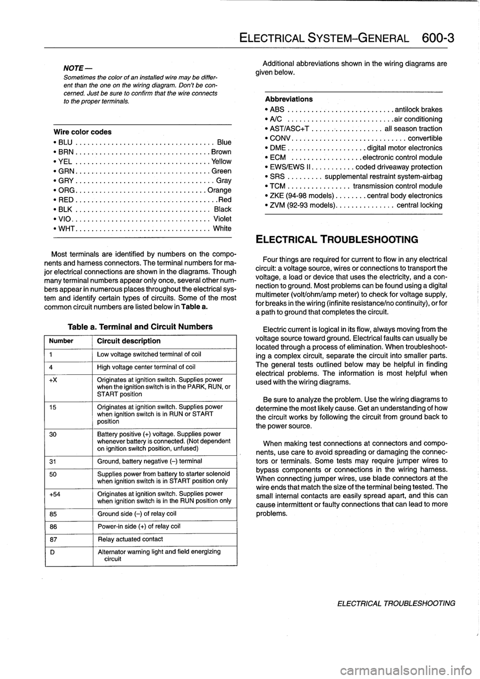
Table
a
.
Terminal
and
Circuit
Numbers
Number
1
Circuít
description
1
j
Low
voltage
switched
terminal
of
coi¡
4
1
High
voltage
center
termina¡
of
coi¡
+x
Originates
atignition
switch
.
Supplies
powerwhen
the
ignition
switch
is
in
the
PARK,
RUN,
or
START
position
15
Originates
atignition
switch
.
Supplies
powerwhen
ignition
switch
is
in
RUN
or
START
position
30
Battery
positive
(+)
voltage
.
Supplies
power
whenever
battery
is
connected
.
(Not
dependent
on
ignition
switch
position,
unfused)
31
1
Ground,
battery
negative
(-)
terminal
50
Supplies
power
from
battery
to
starter
solenoid
when
ignition
switch
isin
START
position
only
+54
Originates
atignition
switch
.
Supplies
power
when
ignition
switch
isin
the
RUN
position
only
85
1
Ground
side
(-)
ofrelay
coil
86
1
Power-in
side
(+)
ofrelay
coil
87
1
Relay
actuatedcontact
D
Alternator
warning
light
and
field
energizing
circuit
ELECTRICAL
SYSTEM-GENERAL
600-
3
Additional
abbreviations
shown
in
the
wiring
diagrams
are
given
below
.
Abbreviations
"
ABS
........
.
...
.
...
.
..........
antilock
brakes
"
A/C
........
.
...
..
..
.
.........
.airconditioning
"
AST/ASC+T
.......
...
.
.
.......
al¡
season
traction
"
CONV
.......
.
.
...
.................
convertible
"
DME
........
.
.
...
.......
digital
motor
electronics
"
ECM
.......
.
...
..
..
.
..
electronic
control
module
"
EWS/EWS
II
......
...
.
.
coded
driveaway
protection
"
SRS
........
.
supplemental
restraint
system-airbag
"
TCM
........
.
..
....
.
transmission
control
module
"
ZKE
(94-98
models)
..
..
.
...
central
body
electronics
"
ZVM
(92-93
models)
...
.
.
..
.
.......
central
locking
ELECTRICAL
TROUBLESHOOTING
Most
terminals
are
identified
by
numbers
on
the
compo-
nents
and
harness
connectors
.
The
terminal
numbers
for
ma-
Four
things
are
required
for
current
toflow
in
any
electrical
jor
electrical
connections
are
shown
in
the
diagrams
.
Though
circuit
:
a
voltagesource,
wires
or
connections
to
transport
the
many
terminal
numbers
appear
only
once,
severa¡other
num-
voltage,
a
load
or
device
that
uses
the
electricity,
and
a
con-
bers
appear
in
numerous
places
throughout
the
electrical
sys-
nection
to
ground
.
Most
problemscanbefound
using
a
digital
tem
and
identify
certain
types
ofcircuits
.
Some
of
the
most
multimeter
(volt/ohm/amp
meter)to
check
for
voltage
supply,
common
circuit
numbers
are
listed
below
in
Table
a
.
for
breaks
in
the
wiring
(infinite
resistance/no
continuity),
orfor
a
path
to
ground
that
completesthe
circuit
.
Electric
current
is
logical
in
its
flow,
always
moving
from
the
voltage
sourcetoward
ground
.
Electricalfaults
can
usually
be
located
through
a
process
of
elimination
.
When
troubleshoot-
ing
a
complex
circuit,
separate
the
circuit
into
smaller
parts
.
The
general
testsoutlined
below
may
be
helpful
in
finding
electrical
problems
.
The
information
is
most
helpful
when
used
with
the
wiring
diagrams
.
Be
sure
to
analyze
the
problem
.
Use
the
wiring
diagrams
to
determine
the
most
likely
cause
.
Getan
understanding
of
how
the
circuit
works
by
following
the
circuit
from
groundback
to
the
power
source
.
When
making
test
connections
at
connectors
andcompo-
nents,
use
care
to
avoidspreading
or
damaging
the
connec-
tors
or
terminals
.
Some
tests
may
require
jumper
wires
to
bypass
components
or
connections
in
the
wiring
harness
.
When
connecting
jumper
wires,
use
bladeconnectors
at
the
wire
ends
that
match
the
size
of
the
terminal
being
tested
.
The
small
interna¡
contacts
are
easily
spread
apart,
and
this
can
cause
intermittent
or
faultyconnections
that
can
leadto
more
problems
.
ELECTRICAL
TROUBLESHOOTING
Page 389 of 759
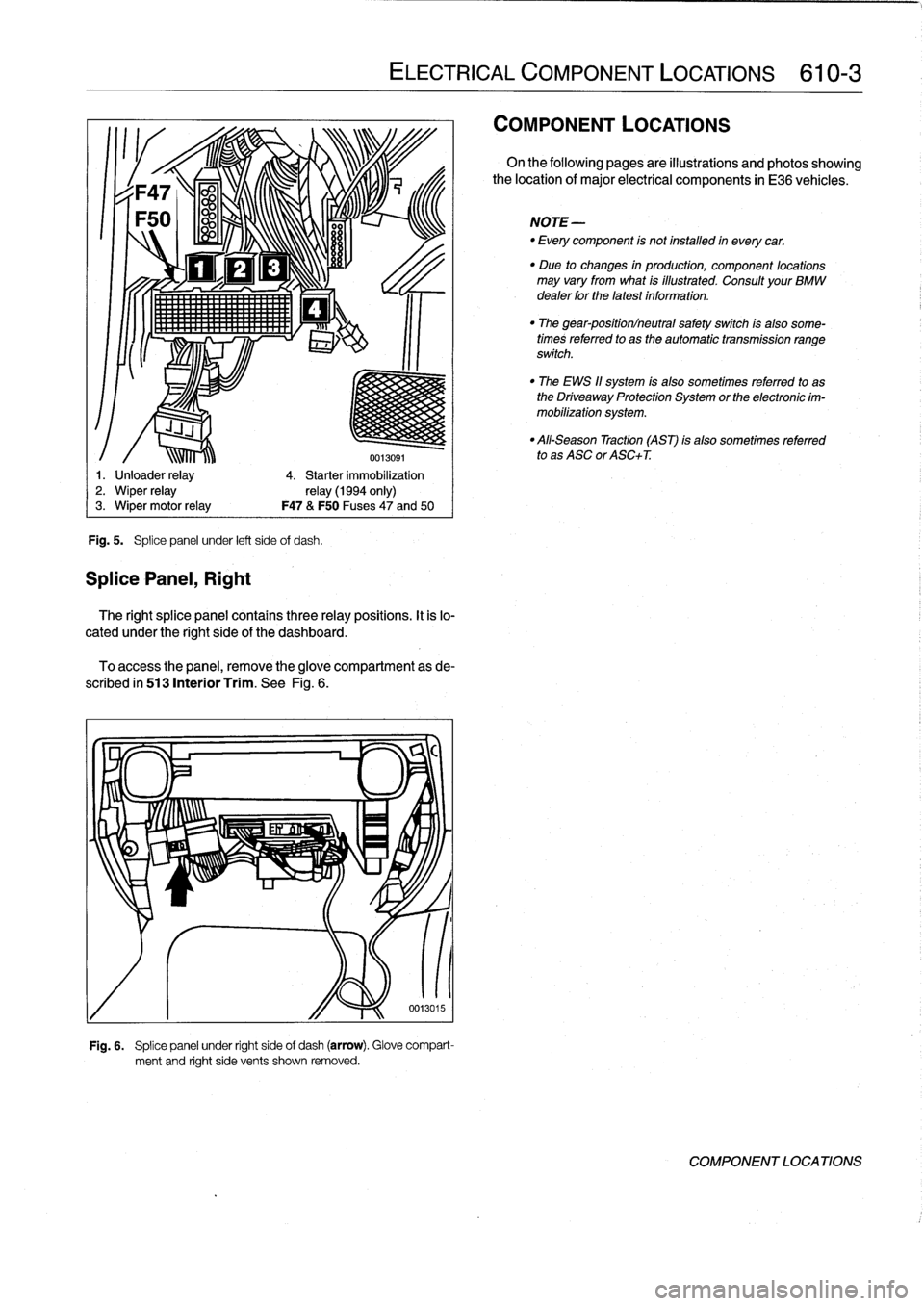
Fig
.
5
.
Splice
panel
under
left
side
of
dash
.
SplicePanel,
Right
ir1!
1,
111lí~lll
.
'
ELECTRICAL
COMPONENT
LOCATIONS
610-3
0013091
1
.
Unloader
relay
4
.
Starter
immobilization
2
.
Wiper
relay
relay
(1994
only)
3
.
Wiper
motor
relay
F47
&
F50
Fuses47
and
50
The
right
splice
panel
contains
three
relay
positions
.
It
is
lo-
cated
under
the
right
side
of
the
dashboard
.
To
access
the
panel,
remove
theglove
compartment
as
de-
scribed
in
513
Interior
Trim
.
See
Fig
.
6
.
Fig
.
6
.
Splice
panel
under
right
side
of
dash
(arrow)
.
Glove
compart-
ment
and
right
side
vents
shown
removed
.
COMPONENT
LOCATIONS
On
the
following
pages
are
illustrations
and
photos
showing
the
location
of
major
electrical
components
in
E36
vehicles
.
NOTE-
-
Every
component
is
not
installed
in
everycar
.
"
Due
to
changes
in
production,
component
locations
may
vary
from
what
is
illustrated
.
Consult
your
BMW
dealer
for
the
latest
information
.
"
The
gear-position/neutral
safety
switch
ís
also
some-
times
referred
to
as
the
automatic
transmission
range
switch
.
"
The
EWS
11
system
is
also
sometimes
referred
to
as
the
Driveaway
Protection
System
or
the
electronic
im-
mobilization
system
.
"
All-Season
Traction
(AST)
is
also
sometimes
referred
to
as
ASC
or
ASC+T
.
COMPONENT
LOCATIONS
Page 403 of 759
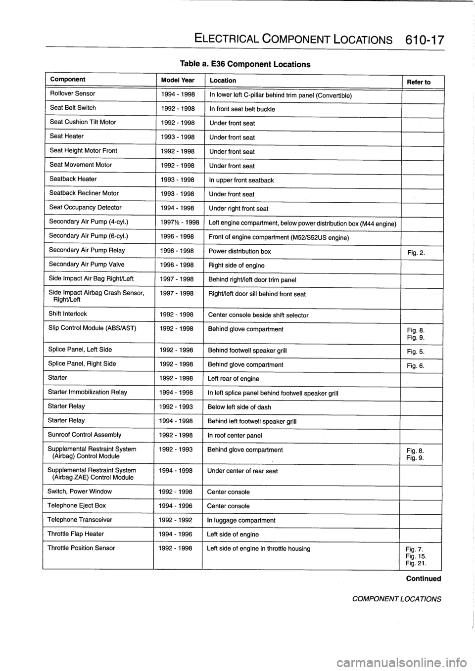
Tablea
.
E36
Component
Locations
Component
Model
Year
Location
Refer
to
Rollover
Sensor
1994-1998
In
lower
left
C-pillar
behind
trim
panel
(Convertible)
Seat
Belt
Switch
1992-1998
In
front
seat
belt
buckle
SeatCushion
Tilt
Motor
1992-1998
Under
front
seat
Seat
Heater
1993-1998
Under
front
seat
Seat
Height
Motor
Front
1992-1998
Under
front
seat
Seat
Movement
Motor
1992-1998
Under
front
seat
Seatback
Heater
1993-1998
In
upper
front
seatback
Seatback
Recliner
Motor
1993-1998
Under
front
seat
Seat
Occupancy
Detector
1994-1998
Under
rightfront
seat
Secondary
Air
Pump
(4-cyl
.)
1997
1
/2
-
1998
Left
engine
compartment,
belowpower
distribution
box
(M44
engine)
Secondary
Air
Pump
(6-cyl
.)
1996-1998
Front
of
engine
compartment
(M52/S52US
engine)
Secondary
Air
Pump
Relay
1996-1998
Power
distribution
box
Fig
.
2
.
Secondary
Air
Pump
Valve
1996-1998
Right
sideof
engine
Side
Impact
Air
Bag
Right/Left
1997-1998
Behind
right/left
door
trim
panel
Síde
Impact
Airbag
Crash
Sensor,
1997-1998
Right/left
door
si¡¡
behind
front
seat
Right/Left
Shift
Interlock
1992-1998
Center
console
beside
shift
selector
Slip
Control
Module
(ABS/AST)
1992-1998
Behind
glove
compartment
Fig
.
8
.
Fig
.
9
.
Splice
Panel,
Left
Side
1992-1998
Behind
footwell
speaker
grill
Fig
.
5
.
SplicePanel,
Right
Side
1992-1998
Behind
glove
compartment
Fig
.
6
.
Starter
1992-1998
Leftrear
of
engine
Starter
Immobilization
Relay
1994-1998
In
left
splice
panelbehind
footwell
speaker
grill
Starter
Relay
1992-1993
Below
left
side
of
dash
Starter
Relay
1994-1998
Behind
left
footwell
speaker
grill
Sunroof
Control
Assembly
1992-1998
In
roof
center
panel
Supplemental
Restraint
System
11992-1993
I
Behind
glove
compartment
I
Fig
.
8
.
(Airbag)
Control
Module
Fig
.
9
.
Supplemental
Restraint
System
1994-1998
1
Under
center
of
rear
seat
(Airbag
ZAE)
Control
Module
Switch,
Power
Window
1
1992-1998
1
Center
console
Telephone
Eject
Box
1
1994-1996
1
Center
console
ELECTRICAL
COMPONENT
LOCATIONS
610-17
Telephone
Transceiver
1992-1992
In
luggage
compartment
Throttle
Flap
Heater
1994-1996
Left
sideof
engine
Throttle
Position
Sensor
1992-1998
I
Left
sideof
engine
inthrottle
housing
I
Fig
.
7
.
Fig
.
15
.
Fig
.
21
.
Continued
COMPONENT
LOCATIONS