check engine light BMW 325Ci CONVERTIBLE 2003 E46 Owner's Manual
[x] Cancel search | Manufacturer: BMW, Model Year: 2003, Model line: 325Ci CONVERTIBLE, Model: BMW 325Ci CONVERTIBLE 2003 E46Pages: 178, PDF Size: 4.59 MB
Page 9 of 178
Contents
9
Passenger safety systems:
Airbags61
Transporting children safely63
Rollover protection system67
Vehicle Memory, Key
Memory69
Driving:
Ignition lock70
Starting the engine70
Switching off the engine72
Parking brake72
Manual transmission73
Automatic transmission with
Steptronic*74
Turn signal indicator/Headlamp
flasher77
Washer/wiper system/Rain
sensor*78
Cruise control*79
Everything under control:
Odometer81
Tachometer81
Energy control81
Fuel gauge82
Engine coolant temperature
gauge82
Service interval display83
Check Control83
Clock84
Computer85
Technology for safety and
driving convenience:
Park Distance Control (PDC)*87
Automatic Stability Control plus
Traction (ASC+T)*88
Dynamic Stability Control
(DSC)*90
Tire Pressure Monitor (TPM)*92
Flat Tire Monitor*93
Lamps:
Parking lamps/Low beams96
Instrument lighting97
High beams/Standing lamps97
Fog lamps*98
Interior lamps98
Controlling the climate for
pleasant driving:
Air conditioning100
Automatic climate control*104
Interior conveniences:
Glove compartment109
BMW Universal Transmitter*110
Storage compartments112
Cellular phone*113
Ashtray, front*113
Ashtray, rear*114
Loading and transporting:
Ski bag*115
Cargo loading116
Roof-mounted luggage rack for
the hardtop*118
Controls and features
handbook.book Page 9 Wednesday, July 31, 2002 9:29 AM
Page 18 of 178
18
Indicator and warning lamps
Technology that monitors itself
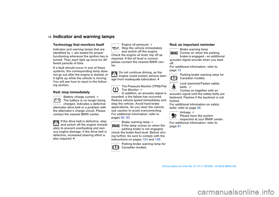
Indicator and warning lamps that are
identified by
●
are tested for proper
functioning whenever the ignition key is
turned. They each light up once for dif-
ferent periods of time.
If a fault should occur in one of these
systems, the corresponding lamp does
not go out after the engine is started, or
it lights up while the vehicle is moving.
You will see how to react in the follow-
ing section.
Red: stop immediately
Battery charge current
●
The battery is no longer being
charged. Indicates a defective
alternator drive belt or a problem with
the alternator's charge circuit. Please
contact the nearest BMW center.
If the drive belt is defective, stop
and switch off the engine immedi-
ately to prevent overheating and seri-
ous engine damage. If the drive belt is
defective, increased steering effort is
also required.
<
Engine oil pressure
●
Stop the vehicle immediately
and switch off the engine.
Check the engine oil level; top off as
required. If the oil level is correct:
please contact the nearest BMW cen-
ter.
Do not continue driving, as the
engine could sustain serious dam-
age from inadequate lubrication.
<
Tire Pressure Monitor (TPM)/Flat
Tire Monitor
●
In addition, an acoustic signal is
sounded: a tire failure has occurred.
Reduce vehicle speed immediately and
stop the vehicle. Avoid hard brake
applications. As you steer the vehicle,
use caution to avoid overcorrecting.
For additional information: refer to
pages 92, 93
Brake warning lamp
●
If the lamp comes on when the
parking brake is not engaged:
check the brake fluid level. Before driv-
ing further, be sure to comply with the
instructions on pages 124 and 139.
Parking brake warning lamp for
Canadian models.
Red: an important reminder
Brake warning lamp
Comes on when the parking
brake is engaged – an additional
acoustic signal sounds when you start
off.
For additional information: refer to
page 72
Parking brake warning lamp for
Canadian models.
Lock backrest/Fasten safety
belts
●
Comes on together with an
acoustic signal until the safety belts are
fastened. Flashes if the backrest is not
locked.
For additional information on safety
belts: refer to page 56
Airbags
●
Please have the system
inspected at your BMW center.
For additional information: refer to
page 61
handbook.book Page 18 Wednesday, July 31, 2002 9:29 AM
Page 82 of 178
82
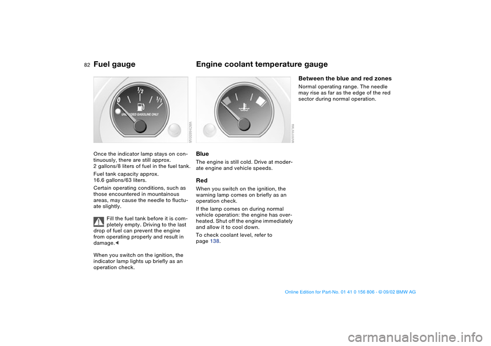
Fuel gaugeOnce the indicator lamp stays on con-
tinuously, there are still approx.
2 gallons/8 liters of fuel in the fuel tank.
Fuel tank capacity approx.
16.6 gallons/63 liters.
Certain operating conditions, such as
those encountered in mountainous
areas, may cause the needle to fluctu-
ate slightly.
Fill the fuel tank before it is com-
pletely empty. Driving to the last
drop of fuel can prevent the engine
from operating properly and result in
damage.<
When you switch on the ignition, the
indicator lamp lights up briefly as an
operation check.
Engine coolant temperature gaugeBlueThe engine is still cold. Drive at moder-
ate engine and vehicle speeds.RedWhen you switch on the ignition, the
warning lamp comes on briefly as an
operation check.
If the lamp comes on during normal
vehicle operation: the engine has over-
heated. Shut off the engine immediately
and allow it to cool down.
To check coolant level, refer to
page 138.
Between the blue and red zonesNormal operating range. The needle
may rise as far as the edge of the red
sector during normal operation.
handbook.book Page 82 Wednesday, July 31, 2002 9:29 AM
Page 92 of 178
92
Tire Pressure Monitor (TPM)*The conceptTPM monitors the tire pressures at all
four tires even while the vehicle is mov-
ing. The system provides an alert when-
ever the inflation pressure drops signifi-
cantly below the specified pressure in
one or more tires.
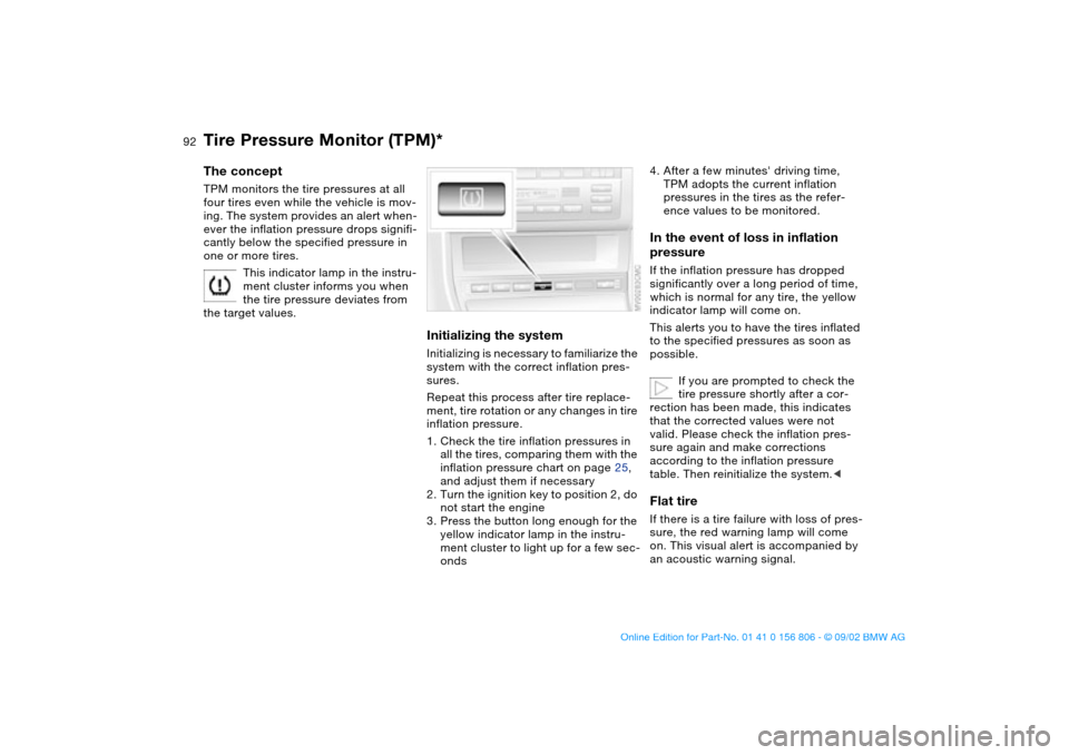
This indicator lamp in the instru-
ment cluster informs you when
the tire pressure deviates from
the target values.
Initializing the systemInitializing is necessary to familiarize the
system with the correct inflation pres-
sures.
Repeat this process after tire replace-
ment, tire rotation or any changes in tire
inflation pressure.
1. Check the tire inflation pressures in
all the tires, comparing them with the
inflation pressure chart on page 25,
and adjust them if necessary
2. Turn the ignition key to position 2, do
not start the engine
3. Press the button long enough for the
yellow indicator lamp in the instru-
ment cluster to light up for a few sec-
onds
4. After a few minutes' driving time,
TPM adopts the current inflation
pressures in the tires as the refer-
ence values to be monitored.In the event of loss in inflation
pressureIf the inflation pressure has dropped
significantly over a long period of time,
which is normal for any tire, the yellow
indicator lamp will come on.
This alerts you to have the tires inflated
to the specified pressures as soon as
possible.
If you are prompted to check the
tire pressure shortly after a cor-
rection has been made, this indicates
that the corrected values were not
valid. Please check the inflation pres-
sure again and make corrections
according to the inflation pressure
table. Then reinitialize the system.
on. This visual alert is accompanied by
an acoustic warning signal.
handbook.book Page 92 Wednesday, July 31, 2002 9:29 AM
Page 138 of 178
138
Coolant
Do not add coolant to the cooling
system when the engine is hot. If
you attempt to do so, escaping coolant
can cause burns.
Antifreeze and anti-corrosion agents
are hazardous to health. You should
always store them in their closed origi-
nal containers and in a location which is
out of reach of children. Antifreeze and
anti-corrosion agents are inflammable.
For this reason, do not spill them on hot
engine parts. They could ignite and
cause serious burns. Comply with the
instructions on the containers.<
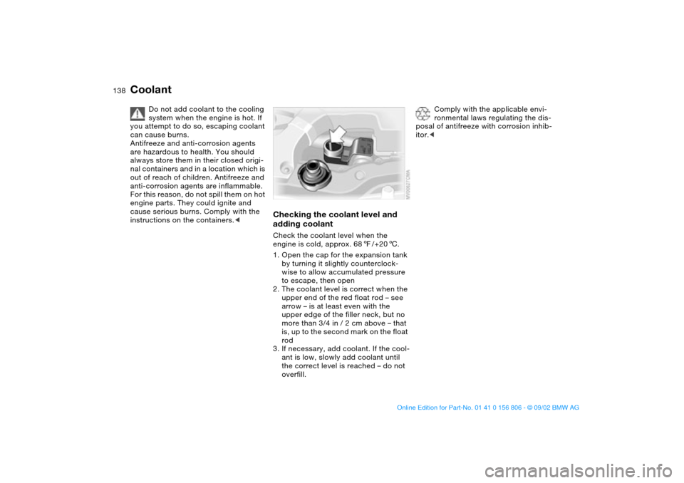
Checking the coolant level and
adding coolantCheck the coolant level when the
engine is cold, approx. 687/+206.
1. Open the cap for the expansion tank
by turning it slightly counterclock-
wise to allow accumulated pressure
to escape, then open
2. The coolant level is correct when the
upper end of the red float rod – see
arrow – is at least even with the
upper edge of the filler neck, but no
more than 3/4 in / 2 cm above – that
is, up to the second mark on the float
rod
3. If necessary, add coolant. If the cool-
ant is low, slowly add coolant until
the correct level is reached – do not
overfill.
Comply with the applicable envi-
ronmental laws regulating the dis-
posal of antifreeze with corrosion inhib-
itor.<
handbook.book Page 138 Wednesday, July 31, 2002 9:29 AM
Page 157 of 178
157 Giving and receiving assistance
Jump-startingWhen your battery is discharged you
can use two jumper cables to start your
vehicle with power from the battery in a
second vehicle. You can also use the
same method to help start another
vehicle. Only use jumper cables with
fully insulated handles on the terminal
clamps.
Do not touch high-voltage wiring
and cables on a running engine.
Contact with components carrying high
voltage can be harmful or fatal. Care-
fully observe the following instructions
to avoid personal injury and/or damage
to one or both vehicles.<
1. The battery in the support vehicle
must also be rated at 12 volts. This
information is provided on the battery
label
2. Stop the engine of the support vehi-
cle and switch off all electrical com-
ponents in both vehicles – except for
the hazard warning flashers of the
support vehicle
3. Make absolutely certain that there is
no contact between the bodywork of
the two vehicles – short circuit haz-
ard
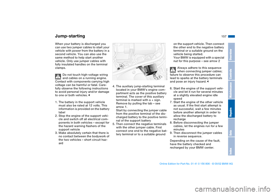
4. The auxiliary jump-starting terminal
located in your BMW's engine com-
partment acts as the positive battery
terminal. The cover of this auxiliary
terminal is marked with a + sign.
Remove by pulling the tab – see
arrow 1.
Start by connecting the jumper cable
from the positive terminal of the dis-
charged battery to the positive termi-
nal of the support battery
5. Then connect the negative terminals
with the other jumper cable. First
connect one end to the negative bat-
tery terminal or to a suitable ground
on the support vehicle. Then connect
the other end to the negative battery
terminal or a suitable ground on the
vehicle being started.
Your BMW is equipped with a special
nut for this purpose – see arrow 2
Always adhere to this sequence
when connecting jumper cables;
failure to observe this procedure can
lead to sparks at the battery terminals
and pose an injury hazard.<
6. Start the engine of the support vehi-
cle and let it run for several minutes
at a slightly elevated engine idle
speed
7. Start the engine of the other vehicle
as usual. If the first start attempt is
not successful, wait a few minutes
before another attempt in order to
allow the discharged battery to
recharge
8. Before disconnecting the jumper
cables, let the engines run for a few
minutes
9. Then disconnect the jumper cables
in reverse sequence.
Depending on the cause of the fault,
have the battery checked and
recharged by your BMW center.
OverviewControlsMaintenanceRepairsDataIndex
handbook.book Page 157 Wednesday, July 31, 2002 9:29 AM
Page 169 of 178
Everything from A to Z
169
Car wash, refer to the Caring
for your vehicle brochure
Cargo loading 116
Cassette player operation,
refer to the Owner's Man-
ual for Radio
CBC Cornering Brake
Control 123
indicator lamp 19
CD player operation, refer to
the Owner's Manual for
Radio
Cellular phone 113
Center armrest 112
Center high-mount brake
lamp 150
Central locking system 30
button 34
Changing a wheel 151
Check Control 83
Check Filler Cap
indicator lamp 19
Checking coolant level 138
Checking oil level 136
Child seats 63
integrated 61
Child-restraint mounting
system (LATCH) 66
Child-restraint system 63
Cigarette lighter 113
Clean headlamps 79Cleaning position, convert-
ible top 45, 50
Cleaning windshield 79
Clock 84
setting 84
Cockpit 14
Code, refer to the Owner's
Manual for Radio
Coin box 113
Compartments 112
Compression ratio 162
Computer 85
Condensation
removing from windows
103, 106
Consumption
display 82
fuel 86
Convertible top
cleaning position 45, 50
closing in an
emergency 48
electrical fault 48
Convertible top activation
fully automatic top 46
manual top 41
Convertible top compart-
ment panel, folding
down 37
Coolant 134, 138, 165
indicator lamp 19
Cooling system 165Copyright 4
Cornering Brake Control
(CBC) 123
indicator lamp 19
Cruise control 79
indicator lamp 20
Cup holder, see Beverage
holder 113
Curb weight 164
Cushion height 163
D
Data
dimensions 163
engine 162
technical 162
weights 164
Daytime driving lamps 96
DBC Dynamic Brake
Control 123
warning lamp 19
Defrost position 103, 106
Defrosting rear window
102, 107
Defrosting windows
103, 106
Digital clock 84
Dimensions 163
Dipstick, engine oil 136
Disc brakes 124
Displacement 162
Display lighting 97Displays 16
Distance warning PDC 87
Door key 30
Door lock buttons 34
Doors
emergency operation 33
manual operation 33
remote control 31
unlocking and locking
31, 33
Driving notes
braking 123
disc brakes 124
general information 123
hydroplaning 123
DSC Dynamic Stability
Control 90
indicator lamp 19
DTC Dynamic Traction
Control 90
Dynamic Brake Control
(DBC) 123
warning lamps 19
Dynamic Stability Control
(DSC) 90
indicator lamp 19
Dynamic Traction Control
(DTC) 90
E
Electric power windows 40
OverviewControlsMaintenanceRepairsDataIndex
handbook.book Page 169 Wednesday, July 31, 2002 9:29 AM
Page 170 of 178
Everything from A to ZElectrical accessories, fail-
ure 156
Electrical malfunction
convertible top 48
doors 33
fuel filler door 24
Emergency operation
closing the convertible
top 48
doors 33
fuel filler door 24
Emergency release
luggage compartment
lid 36
Emissions, minimum, refer
to Energy control 81
Energy control 81
Engine
displacement 162
power output 162
starting 70
switching off 72
torque 162
Engine compartment 134
Engine coolant 165
adding 138
temperature gauge 82
Engine data 162
Engine electronics
warning lamp 19Engine oil
adding 134, 136
capacity 165
consumption 136
quality 137
viscosity 137
Engine oil level
check 134
indicator lamp 19
warning lamp 18
Engine oil pressure
warning lamp 18
Engine oil types 137
Engine speed 162
Entering the rear
rear entry aid 55
Environmentally-friendly
driving, refer to Energy
control 81
Exterior mirrors 59
Eyelet, towing 158
F
False alarm, avoiding 39
Fault displays 83
First-aid kit 23
Flashlight 109
Flat tire 127, 151
Flat Tire Monitor 93
indicator lamp 18, 19
Fog lamps 98
Follow me home lamps 96Footbrake 124
see Driving notes 123
Front fog lamps 98
indicator lamp 20
Front seat adjustment 52
Frost protection
radiator 138
Fuel 25
Fuel consumption 86
display 82
Fuel economy, refer to
Energy control 81
Fuel filler door 24
release following an elec-
trical malfunction 24
Fuel gauge 82
Fuel specifications 25
Fuel tank
capacity 165
display 82
gauge 82
Fuel-injection system 162
Fully automatic convertible
top 46
activation 46
opening, closing 47
Fuses 156
replacing 156
G
Garage-door opener 110Gasoline 25
gauge 82
Glove compartment 109
Grills 100, 104
Gross vehicle weight 164
H
Hands-free system 113
Hardtop 125
Hazard warning flashers 14
Hazard warning triangle 23
Head restraints 54
Headlamp flasher 97
Headlamp washer
reservoir 134
Headlamp washer system
136, 165
Headlamps 96
automatic control 96
Heated mirrors 59
Heated seats 58
Heavy loads 116
High beams 77, 97
indicator lamp 21
replacing bulb 147
Holder for beverages 113
Hood release 132
Horn 14
Hydraulic Brake assistant,
see DBC
Hydroplaning 123, 127
handbook.book Page 170 Wednesday, July 31, 2002 9:29 AM
Page 172 of 178
Everything from A to ZOil additives 137
Oil change intervals, refer to
the Service and Warranty
Information Booklet for US
models/Warranty and Ser-
vice Guide Booklet for
Canadian models
Oil consumption 136
Oil dipstick 136
Oil filter change 165
Oil level
checking 136
indicator lamp 19
warning lamp 18
Oil pressure
warning lamp 18
OIL SERVICE 83
Oil types 137
Onboard computer, refer to
the Owner's Manual for
Onboard Computer
Onboard tool kit 146
Opening and closing
from the inside 34
via the door lock 33
via the remote control 31
Operating elements 14
Outlets, ventilation 104
Outside temperature dis-
play 85P
Panic mode, trigger alarm
32
Park Distance Control
(PDC) 87
Parking aid 87
Parking brake 72
Parking lamps 96
replacing bulb 148
PDC Park Distance
Control 87
Pocket flashlight 109
Pollen 103, 108
Power output 162
Power seat 53
Pressure, tires 25, 92, 127
monitoring 92
R
Radiator 165
Radio, refer to the Owner's
Manual for Radio
Rain sensor 78
Range 86
Reading lamps
front 98
rear 98
Rear lamps 149
Rear window defroster
102, 107
Rearview mirror 59Recirculated-air mode
102, 107
Refueling 24
Remote control 31
Remote control keys 30
Replacement key 30, 31
Reporting safety defects 6
Reserve indicator lamp 82
Restraint system 63
Reverse 73
Rims 130
Rollover protection
system 67
indicator lamp 19
lowering 67
Roof load capacity 164
Roof-mounted luggage rack
118, 125
Run Flat tires 129, 155
S
Safe seating position 52
Safety belts 56
seat-integrated safety belt
system (SGS) 55
Seat
rear entry aid 55
Seat adjustment 52
lumbar support 53
thigh support 53
Seat heating 58
Seat memory 57Securing cargo 116
Securing child-restraint sys-
tem 65
Securing devices 117
Selector lever, automatic
transmission 74
Service and Warranty Infor-
mation Booklet 140
Service Engine Soon
warning lamp 19
Service interval display
83, 140
Setting
clock 84
Shiftlock 74
Side airbags 61
Side turn signal indicators
replacing bulb 149
Size 163
Ski bag 115
Snow chains 131
Socket 114
Spare key 30
Spare tire 151
Speedometer 16
Standing lamps 97
Starting problems 70
Starting the engine 70
Steering wheel lock 70
Steering wheel with multi-
function buttons 22
Steering wheel, adjusting 59
handbook.book Page 172 Wednesday, July 31, 2002 9:29 AM