Flex disc BMW 325i 1992 E36 User Guide
[x] Cancel search | Manufacturer: BMW, Model Year: 1992, Model line: 325i, Model: BMW 325i 1992 E36Pages: 759
Page 281 of 759
9
.
Packeach
CV
joint
and
rubber
boot
with
specified
REAR
SUSPENSION
ARMS
amount
of
lubricant
supplied
.
Apply
adhesive
to
large
end
of
boot
and
mount
it
on
joint
.
Secure
boot
with
clamps
.
The
trailing
arms,
control
arms
and
their
mountingbushings
Apply
sealer
to
inner
CV
joint
dust
cover
and
instan
.
control
the
position
of
the
rear
wheels
.
A
damaged
suspen-
sion
arm
or
worn
bushings
will
change
the
rear
wheel
align
NOTE-
ment
and
may
adversely
affect
handling
and
stability
.
"
Before
installing
each
small
boot
clamp
be
sure
to
"burp"
the
boot
by
flexing
the
CV
joint
as
far
overas
it
WARNING
will
go
.
A
small
screw-driver
inserted
between
the
Do
notattempt
to
straighten
a
damaged
suspension
boot
and
the
axle-shaft
will
help
the
process
.
arm
.
Bending
or
heating
may
weaken
the
original
"
BMW
recommends
Bostil101513
or
EppleC4851
ad-
part
.
If
the
suspension
arm
shows
any
signs
of
hesive,
and
Epple®39
or
Curil©T
sealer
damage
or
excessive
corrosion,
it
must
be
re-
placed
.
CV
Joint
Lubricant
Capacity
"
Wheel
hub
end
ex
.
M3
..
..
.
....
.
.............
80
gram
(2.8
oz
.)
M3
..
...
.
..
.................
100
gram
(3
.5
oz
.)
"
Finaldrive
end
.................
85
gram
(3
.0
oz
.)
10
.
Install
drive
axle
as
described
earlier
.
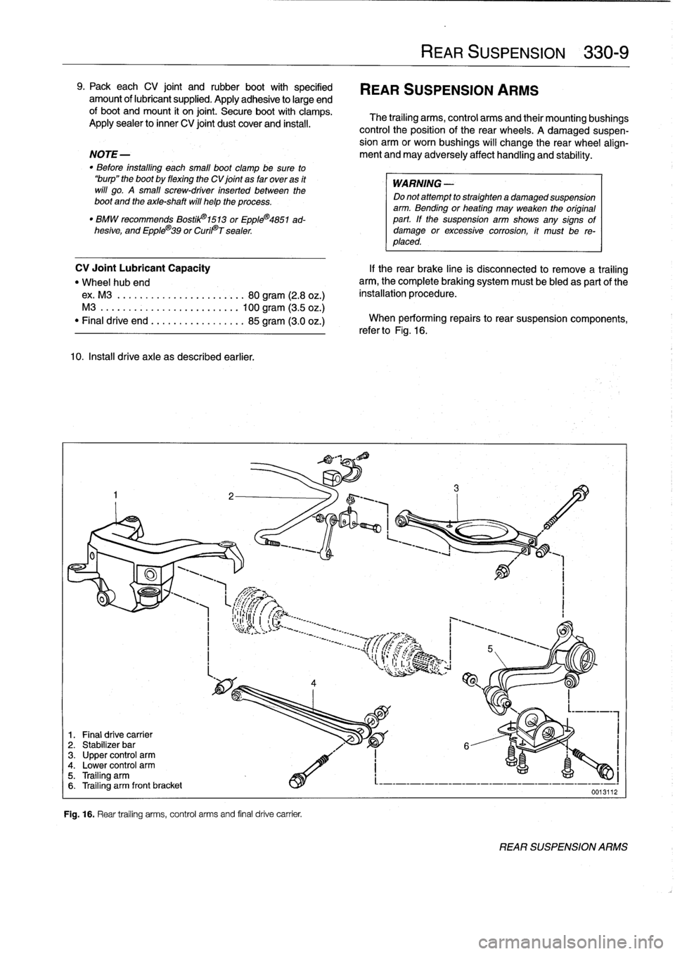
1
.
Final
drive
carrier
2
.
Stabilizer
bar
3
.
Upper
control
arm4
.
Lower
control
arm5
.
Trailing
arm6
.
Trailing
arm
front
bracket
Fig
.
16
.
Rear
trailing
arms,
control
arms
and
final
drive
carrier
.
If
the
rear
brake
cine
is
disconnected
to
remove
a
trailing
arm,
the
complete
braking
system
must
be
bled
as
partof
the
installation
procedure
.
When
performing
repairs
to
rear
suspension
components,
refer
to
Fig
.
16
.
REAR
SUSPENSION
330-
9
0013112
REAR
SUSPENSION
ARMS
Page 289 of 759
Final
driveinputshaft
oil
sea¡,
replacing
1
.
Raise
car
and
support
safely
.
2
.
Drain
final
drive
oil
as
described
earlier
.
3
.
Remove
driveshaft
from
final
drive
inputshaft
flange
.
See
260
Driveshaft
.
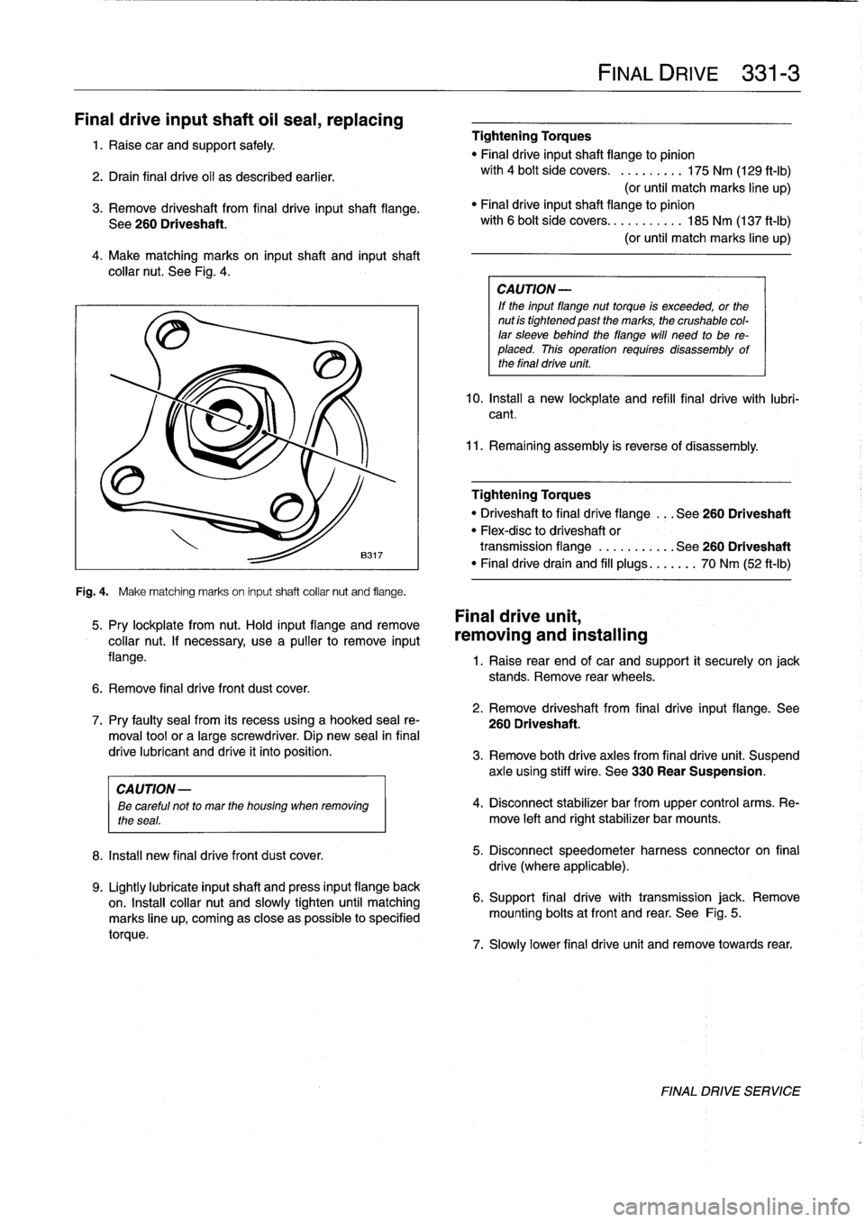
4
.
Make
matching
marks
on
input
shaft
and
inputshaft
collar
nut
.
See
Fig
.
4
.
Fig
.
4
.
Make
matching
marks
on
input
shaft
collar
nut
and
flange
.
5
.
Pry
lockplate
from
nut
.
Hold
input
flange
andremove
collar
nut
.
If
necessary,
usea
pullerto
remove
input
flange
.
6
.
Remove
final
drive
front
dust
cover
.
8
.
Install
new
final
drivefront
dust
cover
.
9
.
Lightly
lubricate
inputshaft
and
press
input
flange
back
on
.
Insta¡¡
collar
nut
and
slowly
tighten
until
matching
marks
line
up,
coming
as
close
aspossible
to
specified
torque
.
Tightening
Torques
"
Final
driveinputshaft
flange
to
pinion
with
4
bolt
side
covers
.
.........
175
Nm
(129
ft-Ib)
(or
until
match
marks
line
up)
"
Finaldriveinputshaft
flange
to
pinion
with
6
bolt
side
covers
...........
185
Nm
(137
ft-Ib)
(or
until
match
marks
line
up)
CA
UTION-
If
the
input
flange
nuttorque
is
exceeded,
or
the
nut
is
tightened
past
the
marks,
the
crushable
col-
lar
sleeve
behind
theflange
will
need
to
be
re-
placed
.
This
operation
requires
disassembly
of
the
final
drive
unit
.
10
.
Install
a
new
lockplate
and
refill
final
drive
with
lubri-
cant
.
11
.
Remaining
assembly
is
reverse
of
disassembly
.
Tightening
Torques
"
Driveshaftto
final
dríve
flange
...
See260
Driveshaft
"
Flex-disc
to
driveshaft
or
transmission
flange
...........
See260
Driveshaft
"
Finaldrivedrain
and
fill
plugs
...
.
..
.
70
Nm
(52
ft-Ib)
Final
drive
unit,
removing
and
installing
FINAL
DRIVE
331-
3
1
.
Raise
rear
end
of
car
and
support
it
securely
on
jack
stands
.
Remove
rear
wheels
.
2
.
Remove
driveshaft
from
final
drive
input
flange
.
See
7
.
Pry
faulty
sea¡
from
its
recess
using
a
hooked
sea¡
re-
260
Driveshaft
.
moval
toolor
a
large
screwdriver
.
Dip
new
sea¡
in
final
drive
lubricant
and
drive
it
into
position
.
3
.
Remove
both
drive
axles
from
final
drive
unit
.
Suspend
axle
using
stiff
wire
.
See
330
Rear
Suspension
.
CAUTION
-
ee
careful
not
to
mar
the
housing
when
removing
4
.
Disconnect
stabilizer
bar
from
upper
control
arms
.
Re-
the
seas
.
move
left
and
rightstabilizer
bar
mounts
.
5
.
Disconnect
speedometer
harness
connector
on
final
drive
(where
applicable)
.
6
.
Support
final
drive
with
transmission
jack
.
Remove
mounting
bolts
atfront
and
rear
.
See
Fig
.
5
.
7
.
Slowly
lower
final
drive
unit
and
remove
towards
rear
.
FINAL
DRIVE
SERVICE
Page 453 of 759
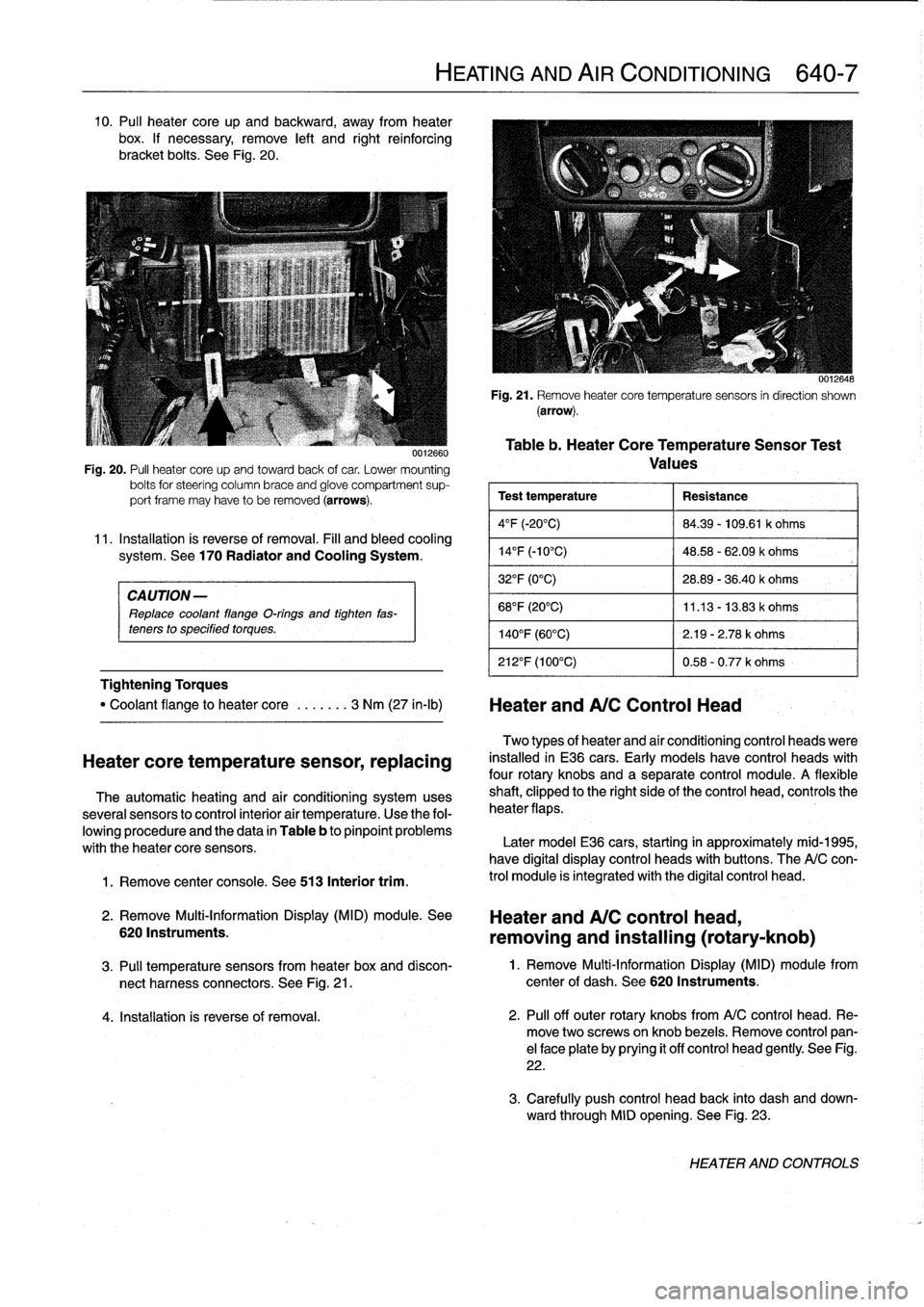
10
.
Pul¡
heater
core
up
and
backward,
away
from
heater
box
.
If
necessary,
remove
left
and
right
reinforcing
bracket
bolts
.
See
Fig
.
20
.
CAUTION-
Replace
coolant
flange
O-rings
and
tighten
fas-
teners
to
specified
torques
.
Tightening
Torques
1
.
Remove
center
console
.
See
513
Interior
trim
.
0012660
Fig
.
20
.
PA
heater
core
upand
towardback
of
car
.
Lower
mounting
bolts
for
steering
column
brace
and
glove
compartment
sup-
port
frame
may
have
to
be
removed
(arrows)
.
11
.
Installation
is
reverse
of
removal
.
Fill
and
bleed
cooling
system
.
See
170
Radiator
and
Cooling
System
.
"
Coolant
flange
to
heater
core
.
..
....
3
Nm
(27
in-lb)
Heater
andA/C
Control
Head
Heatercore
temperature
sensor,
replacing
The
automatic
heating
and
air
conditioning
systemuses
severa¡
sensors
to
control
interior
air
temperature
.
Use
the
fol-
lowing
procedure
and
the
data
in
Table
b
to
pinpoint
problems
with
theheater
core
sensors
.
2
.
Remove
Multi-Information
Display
(MID)
module
.
See
6201nstruments
.
HEATING
AND
AIR
CONDITIONING
640-7
0012648
Fig
.
21
.
Remove
heatercore
temperaturesensors
in
direction
shown
(arrow)
.
Table
b
.
Heater
CoreTemperatureSensor
Test
Values
Test
temperature
Resistance
4°F
(-20°C)
84
.39
-
109
.61
k
ohms
14
°
F
(-10°C)
48
.58
-
62
.09
k
ohms
32°F
(0°C)
28
.89
-
36
.40
k
ohms
68°F
(20°C)
11
.13
-
13
.83
k
ohms
140°F
(60°C)
2
.19
-
2
.78
k
ohms
212°F
(100°C)
0
.58
-
0
.77
k
ohms
Two
types
of
heater
and
aír
conditioning
control
heads
viere
installed
in
E36
cars
.
Early
models
have
control
heads
with
four
rotary
knobs
and
a
separate
control
module
.
A
flexible
shaft,
clipped
to
the
right
sideof
the
control
head,
controls
the
heater
flaps
.
Later
model
E36
cars,
starting
in
approximately
mid-1995,
have
digital
display
control
heads
with
buttons
.
The
A/C
con-
trol
module
is
integrated
with
the
digital
control
head
.
Heater
and
A/C
control
head,
removing
and
installing
(rotary-knob)
3
.
Pul¡
temperature
sensors
from
heater
box
and
discon-
1
.
Remove
Multi-Information
Display
(MID)
module
from
nect
harness
connectors
.
See
Fig
.
21
.
center
of
dash
.
See
620
Instruments
.
4
.
Installation
is
reverse
of
removal
.
2
.
Pul¡
off
outer
rotary
knobs
from
A/C
control
head
.
Re-
move
two
screwsonknob
bezels
.
Remove
control
pan-
el
face
plate
by
prying
it
off
control
head
gently
.
See
Fig
.
22
.
3
.
Carefully
push
control
head
back
into
dash
and
down-
ward
through
MID
opening
.
See
Fig
.
23
.
HEATER
AND
CONTROLS
Page 454 of 759
640-8
HEATING
AND
AIR
CONDITIONING
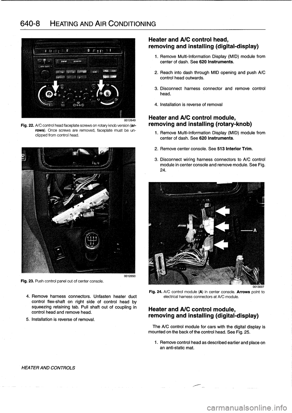
0012649
Fig
.
22
.
A/
C
control
head
faceplate
screwson
rotary
knob
version
(ar-
rows)
.
Once
screws
are
removed,
faceplate
must
be
un-
clipped
from
control
head
.
Fig
.
23
.
Push
control
panel
out
ofcenter
console
.
4
.
Remove
harness
connectors
.
Unfasten
heater
duct
control
flex-shaft
on
right
side
of
control
head
by
squeezing
retaining
tab
.
PA
shaftout
of
coupling
in
control
head
and
remove
head
.
5
.
Installation
is
reverseof
removal
.
HEATER
AND
CONTROLS
0012650
Heater
and
A/C
control
head,
removing
and
installing(digital-display)
1
.
Remove
Multi-Information
Display
(MID)
module
from
center
of
dash
.
See
620
Instruments
.
2
.
Reach
into
dash
through
MID
opening
and
push
A/C
control
head
outwards
.
3
.
Disconnect
harness
connector
and
remove
control
head
.
4
.
Installation
is
reverse
of
removal
Heater
andA/C
control
module,
removing
and
installing
(rotary-knob)
1
.
Remove
Multi-Information
Display
(MID)
module
from
center
of
dash
.
See
620
Instruments
.
2
.
Remove
center
console
.
See
513
Interior
Trim
.
3
.
Disconnect
wiring
harness
connectors
to
A/C
control
module
in
center
console
and
removemodule
.
See
Fig
.
24
.
0013007
Fig
.
24
.
A/
C
control
module
(A)
in
center
console
.
Arrows
point
to
electrical
harness
connectors
at
A/Cmodule
.
Heater
and
A/C
control
module,
removing
and
installing(digital-display)
TheA/C
control
module
for
cars
with
the
digital
display
is
mounted
on
the
back
of
the
control
head
.
See
Fig
.
25
.
1
.
Remove
control
head
as
described
earlier
and
place
onan
anti-static
mat
.
Page 752 of 759
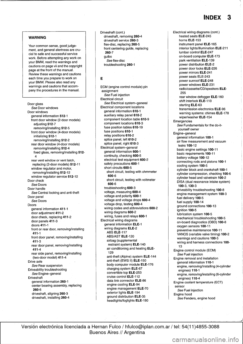
WARNING
Your
common
sense,
good
judge-
ment,
and
general
alertness
are
cru-
cial
to
safe
and
successful
service
work
.
Befcre
attempting
any
work
on
your
BMW,
read
the
warnings
and
cautions
on
page
vi¡
and
the
copyright
page
at
the
frontof
the
manual
.
Review
these
warnings
and
cautions
each
time
you
prepare
to
workon
your
BMW
.
Please
also
read
any
warnings
and
cautions
that
accom-
pany
the
procedures
in
the
manual
.
Door
glass
See
Door
windows
Door
windows
general
information
512-1
front
door
window
(2-door
models)
adjusting
512-7
removing/installing
512-5
front
door
window
(4-door
models)
initíalizing
512-1
removing/installing
512-2
rear
door
window
(4-door
models)
removing/installing
512-4
fixed
glass,
removing/installing
512-
4
rear
vent
window
or
vent
latch,
replacing
(2-door
models)
512-11
window
regulator
and
motor,
removing/installing
512-12
window
regulator
service
512-12Doorcheck
See
DoorsDoor
handle
See
Centrallocking
and
anti-theft
Door
panel
See
Doors
Doors
general
information
411-1
door
adjustment
411-2door
check,
replacing
411-2
door
panels
411-3
doors411-1
front
orrear
door,removing/installing
411-1
front
door
panel,
removing/installing
411-3
rear
door
panel,
removing/installing
411-4
rearsidepanel,
removing/installing
(two-door
model)
411-4
Drive
axle
See
Rear
suspension
Driveability
troubleshooting
See
Engine-general
Driveshaft
general
information
260-1
center
bearing
assembly,
replacing
260-6
driveshaft,
aligning
260-3
driveshaft,
installing
260-4
Driveshaft
(cont
.)
driveshaft,
removing260-4
driveshaftservice
260-3
flex-disc,
replacing
260-5
front
centering
guide,
replacing
260-7
guibo
See
flex-disc
troubleshooting260-1
ECM
(engine
control
module)
pin
assignment
See
Fuel
injection
Electrical
circuit
See
Electrical
system-general
Electrical
component
locations
general
information
610-1
auxíliary
relay
panel
610-2
component
location
table
610-9
component
locations
610-3
fuse
position
tables
610-19
fuse
positions
610-1
relay
positions
610-2
splice
panel,
left
610-2
splice
panel,
right
610-3
Electrical
system-general
general
information
600-1
continuity,
checking
600-5
electrical
test
equipment
600-2
safety
precautions
600-1
short
circuits
600-5
short
circuit,
testing
with
ohmmeter
600-6
short
circuit,
testing
with
voltmeter
600-6
troubleshooting
600-3
voltage,
measuring600-4
voltage
and
polarity
600-1
voltage
and
voltage
drops
600-4
voltage
drop,
testing
600-4
wiring
codes
and
abbreviations
600-2
wiring
diagrams
600-2
wiring,
fuses
and
relays
600-1
Electrical
wiring
diagrams
general
information
ELE-1
wiring
diagrams
ELE-2
ABS
ELE-117
ABS/AST
ELE-120
airbag
(supplemental
restraint
system)
ELE-140
air
conditioning
and
heating
ELE-
129
anti-theft
(Alpine)
system
ELE-144
anti-theft
(EWS
II)
ELE-150
body
computer
module
ELE-176
charging
system
ELE-67
convertible
top
ELE-253
cruise
control
ELE-112
data
link
connector
ELE-86
engine
cooling
ELE-94
engine
management
ELE-70
exterior
lights
ELE-194
ground
distribution
ELE-35
headlights/foglights
ELE-180
INDEX
3
Electrical
wiring
diagrams
(cont
.)
heated
seats
ELE-245
horns
ELE-153
instrument
panel
ELE-165
interior
lights/illumination
ELE-211
lumbar
control
ELE-247
on-board
computer
ELE-173
park
ventilation
ELE-139
power
distribution
ELE-2
power
door
locks
ELE-226
power
mirrors
ELE-241
power
seats
ELE-243
power
sunroof
ELE-248
power
windows
ELE-231
radio/cassette/CD/speakers
ELE-
255
rear
window
defogger
ELE-160
shift
interlock
ELE-110
starting
ELE-63
transmission
electronics
ELE-96
warning
systems`
.
chimes
ELE-178
wiper/washer
ELE-154
Emergencies
See
Fundamentals
for
the
do-it-
yourself
owner
Engine-general
general
information
100-1
air
flow
measurement
and
vacuum
leaks
100-12
basic
engine
settings
100-11
basic
requirements
100-11
battery
voltage
100-12connecting
rods
and
pistons
100-1
cooling
system
100-5
cylinder
block
and
crankshaft100-1
cylinder
compression,
checking
100-6
cylinder
head
and
valvetrain
100-2
DISA
(dual
resonance
intake
system)
100-3,130-3
driveability
troubleshooting
100-8
engine
management
system
100-3
fuel
delivery
100-5
fuel
supply
100-14ground
connections
100-13
ignition
100-5
lubrication
system100-5
mechanical
troubleshooting
100-5
on-board
diagnostics
(OBD)
100-8
oxygen
sensors
100-11
preventive
maintenance
100-11
VANOS
(variable
valve
timing)
100-2warningsand
cautions
100-5
wiring
andharness
connections100-
13Engine
control
module
(ECM)
See
Fuel
injection
Engine
removal
and
installation
general
information
110-1
engine,
removing/installing(4-cylinder
engines)
110-1
engine,
removing/installing
(6-cylinder
engines)
110-4
Engine
coolant
temperature
(ECT)
sensor
See
Fuel
injection
Engine
hood
See
Fenders,
enginehood
Page 753 of 759
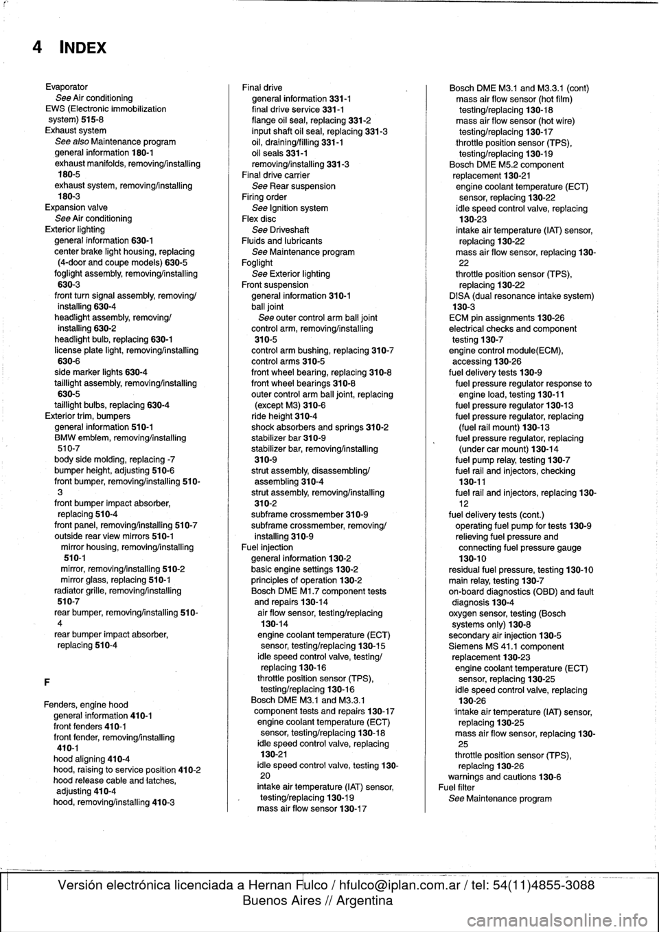
4
INDEX
Evaporator
See
Air
conditioning
EWS
(Electronic
immobilization
system)
515-8
Exhaust
system
See
also
Maintenance
program
general
information
180-1
exhaust
manifolds,
removingAnstalling
180-5
exhaustsystem,
removing/installing
180-3
Expansion
valve
See
Air
conditioning
Exterior
lighting
general
information
630-1
center
brake
light
housing,
replacing
(4-door
and
coupe
models)
630-5
foglight
assembly,
removing/installing
630-3
front
turn
signal
assembly,
removing/
installing
630-4
headlight
assembly,removing/
installing
630-2
headlight
bulb,
replacing
630-1
license
plate
light,
removing/installing
630-6
side
marker
lights
630-4
taillight
assembly,
removing/installing
630-5
taillight
bulbs,
replacing
630-4
Exterior
trim,
bumpers
general
information
510-1
BMW
embiem,
removing/installing
510-7
body
side
molding,
replacing
-7
bumper
height,
adjusting
510-6
front
bumper,
removing/installing
510-3
front
bumper
impact
absorber,
replacing
510-4
front
panel,
removing/installing
510-7
outside
rear
view
mirrors
510-1
mirror
housing,
removing/installing
510-1
mírror,
removing/installing
510-2
mirror
glass,
replacing
510-1
radiator
grille,
removing/installing
510-7
rear
bumper,
removingfinstalling
510-
4
rear
bumper
impact
absorber,
replacing
510-4
F
Fenders,
engine
hood
general
information
410-1
front
fenders
410-1
front
fender,
removing/installing
410-1
hood
aligning
410-4
hood,
raising
to
service
position
410-2
hood
release
cable
and
latches,
adjusting
410-4
hood,
removing/installing
410-3
Finaldrive
general
information
331-1
final
drive
se
rvice
331-1
flange
oil
sea¡,
replacing
331-2
inputshaft
oil
sea¡,
replacing
331-3
oil,
draining/filling
331-1
oil
seals331-1
removing/installing
331-3
Final
drive
carrier
See
Rear
suspension
Firing
order
See
Ignition
system
Flexdisc
See
DriveshaftFluids
and
lubricants
See
Maintenance
program
Foglight
See
Exterior
lighting
Front
suspension
general
information
310-1
ball
joint
See
outer
control
arm
ball
joint
control
arm,
removing/installing
310-5
control
arm
bushing,
replacing
310-7
control
arms
310-5
front
wheel
bearing,
replacing
310-8
front
wheel
bearings
310-8
outer
control
arm
ball
joint,
replacing
(except
M3)310-6
ride
height
310-4shock
absorbers
and
springs
310-2
stabilizer
bar
310-9
stabilizer
bar,
removing/installing
310-9
strut
assembly,disassembling/
assembling310-4
strut
assembly,
removing/installing
310-2subframe
crossmember
310-9subframe
crossmember,
removing/
installing
310-9
Fuel
injection
general
information
130-2
basic
engine
settings
130-2
principies
of
operatínn
130-2
Bosch
DME
Ml
.7
component
tests
and
repairs
130-14
air
floiv
sensor,testing/replacing
130-14
engine
coolant
temperature
(ECT)
sensor,
testing/replacing
130-15
¡dle
speed
control
valve,
testing/
replacing
130-16
throttle
position
sensor
(TPS),
testing/replacing
130-16
Bosch
DME
M3
.1
and
M3
.3
.1
component
tests
and
repairs
130-17
engine
coolant
temperature
(ECT)
sensor,
testing/replacing
130-18
¡dle
speed
control
valve,
replacing
130-21
¡dle
speed
control
valve,
testing
130-
20
intake
air
temperature
(IAT)
sensor,
testing/replacing
130-19
mass
air
flow
sensor130-17
Bosch
DME
M3
.1
and
M3
.3.1
(cont)
mass
air
flow
sensor
(hot
film)
testing/replacing
130-18
mass
air
flow
sensor
(hot
wire)
testing/replacing
130-17
throttle
position
sensor
(TPS),
testing/replacing
130-19
Bosch
DME
M5
.2
component
replacement
130-21engine
coolant
temperature
(ECT)
sensor,
replacing
130-22
ldle
speed
control
valve,
replacing
130-23
intake
air
temperature
(IAT)
sensor,
replacing
130-22
mass
air
flow
sensor,
replacing
130-
22
throttle
position
sensor
(TPS),
replacing
130-22
DISA
(dual
resonance
intake
system)
130-3
ECM
pin
assignments130-26
electrical
checks
andcomponent
testing
130-7engine
control
module(ECM),
accessing
130-26
fuel
delivery
tests
130-9
fuel
pressure
regulator
response
to
engine
load,
testing
130-11
fuel
pressure
regulator
130-13
fuel
pressure
regulator,
replacing
(fuel
rail
mount)130-13
fuel
pressure
regulator,
replacing
(under
car
mount)130-14
fuel
pump
relay,
testing
130-7
fuel
rail
and
injectors,
checking
130-11
fuel
rail
and
injectors,
replacing
130-
12
fuel
delivery
tests
(cont
.)
operatíng
fuel
pump
for
tests
130-9
relieving
fuel
pressure
and
connecting
fuel
pressure
gauge
130-10
residual
fuel
pressure,
testing
130-10
main
relay,
testing
130-7on-board
diagnostics
(OBD)
and
fault
diagnosis
130-4
oxygen
sensor,
testing
(Bosch
systems
only)
130-8
secondary
air
injection
130-5
Siemens
MS
41
.1
component
replacement
130-23
engine
coolant
temperature
(ECT)
sensor,
replacing
130-25
¡dle
speed
control
valve,
replacing
130-26
lntake
air
temperature
(IAT)
sensor,
replacing
130-25
mass
air
flow
sensor,
replacing
130-
25
throttle
position
sensor
(TPS),
replacing
130-26warnings
and
cautions
130-6
Fuel
filter
See
Maintenance
program
Page 754 of 759
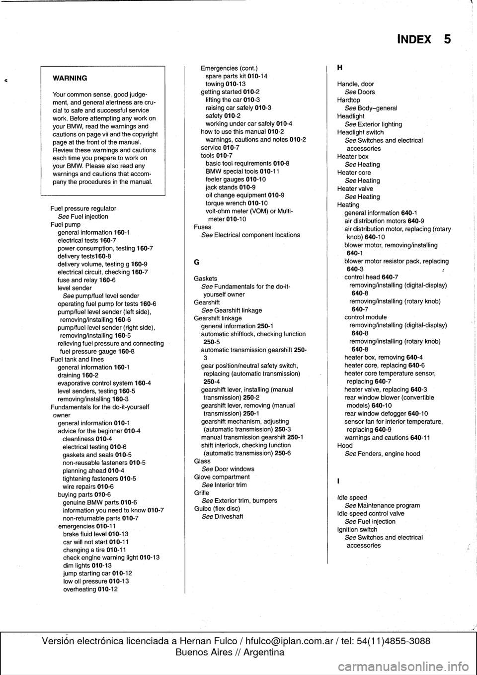
WARNING
Your
common
sense,
good
judge-
ment,
and
general
alertness
are
cru-
cial
tosafe
and
successful
service
work
.
Before
attempting
any
work
on
your
BMW,
read
the
warnings
and
cautions
on
page
vi¡
and
the
copyright
page
at
the
frontof
the
manual
.
Review
these
warnings
and
cautions
each
time
you
prepare
to
work
on
your
BMW
.
Please
also
read
any
warnings
and
cautions
that
accom-
pany
the
procedures
in
the
manual
.
Fuel
pressure
regulator
See
Fuel
injection
Fue]
pump
general
information
160-1
electrical
tests
160-7
power
consumption,
testing
160-7
delivery
tests160-8
delivery
volume,
testing
g
160-9
electrical
circuit,
checking
160-7
fuse
and
relay
160-6
level
sender
See
pump/fuel
leve¡
sender
operating
fuel
pump
for
tests
160-6
pump/fuel
level
sender
(left
side),
removing/installing
160-6
pump/fuel
leve¡
sender
(right
side),
removing/installing
160-5
relieving
fuel
pressure
and
connecting
fue¡
pressure
gauge
160-8
Fueltank
and
lines
general
information
160-1
draining
160-2
evaporative
control
system
160-4
leve¡
senders,
testing
160-5
removing/installing
160-3
Fundamentals
for
the
do-it-yourself
owner
general
information
010-1
advice
for
the
beginner
010-4
cleanliness
010-4
electrical
testing
010-6
gaskets
and
seals
010-5
non-reusable
fasteners
010-5
planning
ahead
010-4
tightening
fasteners
010-5
wire
repairs
010-6
buying
parts
010-6
genuine
BMW
parts
010-6
information
you
need
to
know
010-7
non-returnable
parts
010-7
emergencies
010-11brake
fluid
leve¡
010-13
car
will
not
start
010-11
changinga
tire
010-11
check
enginewarning
light
010-13
dim
Iights
010-13
jump
starting
car
010-12
low
o]I
pressure
010-13
overheating
010-12
Emergencies
(cont
.)
spare
parts
kit
010-14
towing
010-13
gettingstarted
010-2
lifting
thecar
010-3
raising
car
safely
010-3
safety
010-2
working
under
car
safely
010-4
how
to
use
this
manual
010-2
warnings,
cautions
and
notes
010-2
service
010-7
tools
010-7
basic
tool
requirements010-8
BMW
specialtools
010-11
feeler
gauges
010-10
jack
stands
010-9
oil
change
equipment
010-9
torque
wrench
010-10
volt-ohm
meter
(VOM)
or
Multi-
meter010-10
Fuses
See
Electrical
component
locations
G
Gaskets
See
Fundamentals
for
the
do-it-
yourself
owner
Gearshift
See
Gearshift
linkage
Gearshift
linkagegeneral
information
250-1
automatic
shiftlock,
checking
function
250-5
automatic
transmission
gearshift
250-
3
gear
position/neutral
safety
switch,
replacing
(automatic
transmission)
250-4
gearshift
lever,
installing
(manual
transmission)
250-2
gearshift
lever,
removing
(manual
transmission)
250-1
gearshift
mechanism,
adjusting
(automatictransmission)
250-3
manual
transmission
gearshift
250-1
shift
interlock,
checking
function
(automatic
transmission)
250-6Glass
See
Door
windows
Glove
compartment
See
Interior
trim
Grille
See
Exterior
trim,
bumpers
Guibo
(flex
disc)
See
Driveshaft
Handle,
door
See
Doors
Hardtop
See
Body-general
Headlight
See
Exterior
lighting
Headlight
switch
See
Switches
and
electrical
accessoriesHeater
box
See
Heating
Heater
core
See
Heating
Heater
valve
See
Heating
Heating
general
information
640-1
air
distribution
motors
640-9
air
distribution
motor,
replacing
(rotary
knob)
640-10
blower
motor,
removing/installing
640-1blower
motor
resistor
pack,
replacing
640-3
control
head
640-7
removing/installing
(digital-display)
640-8
removing/installing
(rotary
knob)
640-7
control
module
removing/installing
(digital-display)
640-8
removing/installing
(rotary
knob)
640-8
heater
box,
removing640-4
heater
core,
replacing
640-6
heater
core
temperature
sensor,
replacing
640-7
heater
valve,
replacing
640-3
rear
window
blower
(convertible
models)
640-10
reas
window
defogger
640-10sensor
fan
forinterior
temperature,
replacing
640-9warnings
and
cautions
640-11
Hood
See
Fenders,
engine
hood
Idle
speed
See
Maintenance
program
Idle
speed
control
valve
See
Fuel
injection
Ignition
switch
See
Switches
and
electrical
accessories
INDEX
5