Rear window BMW 325i 1992 E36 Owner's Manual
[x] Cancel search | Manufacturer: BMW, Model Year: 1992, Model line: 325i, Model: BMW 325i 1992 E36Pages: 759
Page 345 of 759
GENERAL
This
repair
group
covers
interior
trim
removal
and
installa-
tion
procedures
.
Forremoval
and
installation
of
interior
switches,
including
interior
lighting
equipment,
see
612
Switches
and
Electrical
Accessories
.
Most
of
the
interior
trim
and
finish
paneis
are
clipped
or
screwed
into
place
.
Many
of
the
trim
retaining
clips
arede-
signed
to
be
used
only
once
.
When
removing
trim
that
is
held
in
place
with
clips,
it
is
a
good
idea
lo
have
spareson
hand
be-
fore
beginningthejob
.
CENTER
CONSOLE
The
front
section
center
console
houses
the
Multi-Informa-
tion
Display
(MID)
module,the
front
ashtray
and
cigarette
lighter
;
shifter
lever,
power
window
switches
and
the
hazard
warning
switch
.
The
rear
center
console
section
houses
the
ashtray(s)
and
covers
the
emergency
brakecable
ends
.
Center
console,
removing
and
installing
1
.
Disconnect
negative
(-)
cable
from
battery
and
cover
terminal
with
insulating
material
.
CA
UTION-
Prior
to
disconnectiog
the
battery,
read
the
battery
disconnection
cautionsgiven
at
the
front
of
this
manual
onpage
viii
.
2
.
Remove
shifter
boot
or
selectorlever
cover
.
See250
Gearshift
t-inkage
.
3
.
Remove
rear
ashtray
retaining
screws
totake
out
ash-
tray
.
Remove
rear
console
retaining
screwunder
ash-
tray
.
513
Interior
Tri
m
INTERIORTRIM
513-1
GENERAL
..
.
.....
.
.
.
.
.
.
.
.
.
.
.
......
.
.
.
513-1
DASHBOARD
.....
.
.
.
.
.
.
.
.
.
.
.
.
.
.
...
.
:
.
.513-2
Glove
compartment,removing
and
installing
.
.513-2
CENTER
CONSOLE
.
.
.
.
.
.
.
.
.
.
.........
513-1
Lower
left
dash
panel,
Center
console,
removing
and
installing
.....
513-1
removing
and
installing
.
.
.
.
.
.
.
.
.
.
.....
.
.
513-2
Dashboard,removing
and
installing
.
.
.
.
...
.
.513-3
4
.
Remove
Multi-Information
Display
module
.
See620
In-
struments
.
5
.
Remove
hazardwarning
switch
and
power
window
switches
bypushing
up
and
out
from
below
.
6
.
Remove
lower
left
dashboard
panel
and
glove
compart-
ment
as
described
later
in
this
repair
group
.
7
.
Remove
retaining
screwunder
hazard
light
switch
.
Pull
rear
console
back
and
remove
retaining
nut
at
back
of
front
console
.
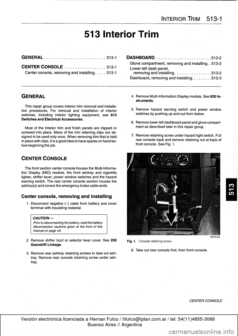
See
Fig
.
1
.
Fig
.1.
Console
retaining
screw
.
8
.
Take
out
rear
console
first,
then
front
console
.
0013154
CENTER
CONSOLE
Page 349 of 759
515
Central
Locking
and
Anti-Theft
GENERAL
.....
.
.
.
.
.
.
.
..:
.
.
.
......
.
.
.
.
515-1
Luggage
compartment
locking
actuator,
removing
and
installing
.
.
.
.
.
...........
.
515-6
DOOR
HANDLES
AND
LOCKS
.........
515-1
LOCKING
SYSTEM
AND
Front
door
lock,
removing
and
installing
....
.515-1
ELECTRONIC
IMMOBILIZATION
......
.515-7
Front
door
handle,
removing
and
installing
...
515-3
Rear
door
lock,
removing
and
installing
.....
515-4
Central
Locking
System(ZVM)
.
.
.
.
.......
.
515-7
Rear
door
handle,
removing
and
installing
...
515-5
Central
Body
Electronics
(ZKE
IV)
.
.
.......
.515-8
Electronic
Immobilization
System
(EWS)
.
.
.
.
.515-8
Door
striker,
rep
lacing
.
.
.
.
.
.
.
.
.
..........
515-6
EWS
II
control
module,
re
lacin
515-10
LOCKING
ACTUATORS
.
.
.
.
.
.
..........
515-6
Ring
antenna,
replacing
.
.
.
.
.
.
.
.
.
.
...
.
.
.
.
515-10
Door
Locking
Actuator
.
.
.
.
.
.
.
.
..........
515-6
EWS
II
transmitter/receiver
module,
replacing
...........
.
.
.
.
.
.
.
.
.
.
.
.
.
.
.
.
515-11
GENERAL
This
section
covers
repair
information
for
the
central
locking
and
the
anti-theft
systems
.
Keep
in
mind
that
E36
cars
are
CA
UTION-
equipped
with
sophisticated
and
self-diagnostic
electrical
sys-
Prior
to
disconnecting
the
battery,
read
the
battery
tems
.
When
experiencing
malfunctions
relatinglo
the
central
disconnection
cautions
given
at
the
front
of
this
locking
or
the
anti-theft
system,
it
is
recommended
that
the
manual
onpage
vi¡¡
.
systembe
diagnosed
using
the
BMW
service
tester
(DIS)
.
This
advanced
diagnostic
tool
can
usually
pinpoint
electrical
NOTE-
faults
quickly
and
safely
.
Consult
an
authorized
BMW
dealer
.
In
some
models
covered
inthis
manual,
it
is
not
essen-
tial
to
remove
the
side-impact
airbag
to
access
intemal
NOTE-
door
components
.
However,
the
procedure
is
recom-
Additional
general
electrical
information
can
be
found
mended
for
safely
reasons
.
i
n
610
Electrical
Component
Locations
and
Electri-
cal
Wiring
Diagrams
.
4
.
Disconnect
harnessconnector
from
window
motor
to
DOOR
HANDLES
AND
LOCKS
Front
door
lock,
removing
and
installing
1
.
Remove
front
door
panel
and
vapor
barrier
asde-
scribed
in
411
Doors
.
WARNING
-
Some
1997
and
all
1998
cars
are
fitted
with
side-im-
pact
airbags
in
the
front
doors
.
When
servicing
the
door
locks
on
cars
with
front
side-impact
airbags,
al-
ways
disconnect
the
negative
(-)
battery
terminal
.
See721
Airbag
System
(SRS)
forcautions
andpro-
cedures
relating
to
the
airbag
system
.
2
.
Raise
door
window
completely
CENTRAL
LOCKING
AND
ANTI-THEFT
515-1
3
.
On
cars
with
side-impact
airbags,
disconnect
negative
(-)
cable
from
battery,
then
remove
airbag
module
.
prevent
accidental
operation
.
5
.
On
4-door
cars
:
Peel
back
rubber
window
guide
from
reas
guide
rail
:
Remove
guide
rail
mounting
boltat
bot-
tom
.
Unclip
any
wiring
from
guide
rail
and
pull
guide
rail
downward
and
remove
from
door
.
See
Fig
.
1
.
NOTE
-
The
top
of
the
guide
rail
is
"hooked"
to
the
doorsheet
metal
.
6
.
Remove
inside
door
handle
retaining
screw
.
Discon-
nect
inside
handle
from
linkage
and
remove
.
See
Fig
.
2
.
7
.
Cut
wire
ties
and
remove
door
lock
electrical
harness
con-
nector
.
Remove
door
lock
mounting
screws
.
See
Fig
.
3
.
8
.
Working
inside
door,
disconnect
outside
door
handle
and
lockcylinder
linkage
from
door
lock
.
Remove
lock
from
inside
door
.
See
Fig
.
4
.
DOOR
HANDLES
AND
LOCKS
Page 350 of 759
515-2
CENTRAL
LOCKING
AND
ANTI-THEFT
0013117
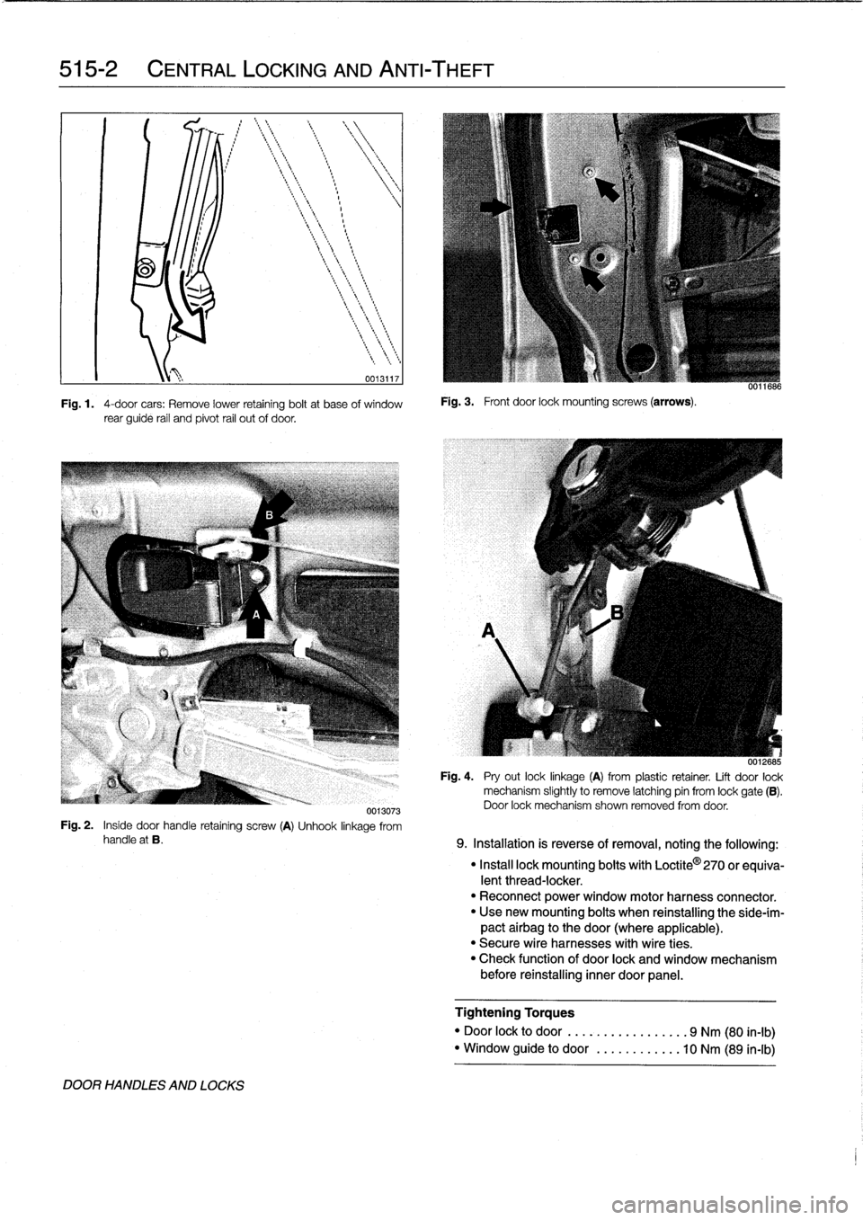
Fig
.
1
.
4-door
cars
:
Remove
lower
retaining
boltat
base
of
window
rear
guide
rail
and
pivot
rail
out
of
door
.
Fig
.
3
.
Front
door
lock
mounting
screws
(arrows)
.
uu11686
0012685
Fig
.
4
.
Pry
out
locklinkage
(A)
from
plastic
retainer
.
Lift
door
lock
mechanism
slightly
to
Rmove
latching
pin
from
lock
gate
(B)
.
Door
lock
mechanism
shown
removed
from
door
.
0013073
Fig
.
2
.
Inside
door
handle
retaining
screw
(A)
Unhook
linkage
from
handle
at
B
.
9
.
Installation
is
reverse
of
removal,
noting
the
following
:
DOOR
HANDLES
AND
LOCKS
"
Install
lock
mounting
bolts
with
Loctite
0
270
or
equiva-
lent
thread-locker
.
"
Reconnect
power
window
motor
harness
connector
.
"
Usenew
mounting
bolts
when
reinstalling
the
side-ím-
pact
airbag
to
the
door
(where
applicable)
.
"
Secure
wire
harnesses
with
wire
ties
.
"
Check
function
of
door
lock
and
window
mechanism
before
reinstalling
inner
door
panel
.
Tightening
Torques
"
Door
lock
to
door
......
.
..........
9
Nm
(80
in-lb)
"
Window
guide
to
door
........
.
...
10
Nm
(89
in-lb)
Page 352 of 759
515-4
CENTRAL
LOCKING
AND
ANTI-THEFT
11
.
Installation
is
reverse
of
removal
.
Keep
in
mind
the
fol-
4
.
Remove
screws
mounting
bottom
of
window
rear
track
lowing
:
to
door
.
See
Fig
.
9
.
"
Make
sure
rubber
seal
for
handle
is
correctly
posi-
tionedbefore
tightening
mounting
fasteners
.
"
Install
exteriortrim
piece
and
then
use
a
hooked
tool
to
pull
locking
plate
into
locked
position
.
Make
sure
door
handle
trim
contacts
body
evenly
before
locking
trim
in
place
.
"
Use
new
mounting
bolts
when
reinstalling
the
side-im-
pactairbag
to
the
door(where
applicable)
.
Reset
SRS
warning
light
and
clear
SRS
fault
memory
using
spe-
cial
test
equipment
.
See
721
Airbag
System
(SRS)
.
"
Reconnect
al¡
harness
connectors
(including
power
window
motor)before
installing
door
panel
.
"
Secure
wire
harnesses
withwire
ties
.
"
Adjust
and
reinitialize
windows
.
See
512
Door
Win-
dows
.
Tightening
Torque
"
Collar
nut
to
doorhandle
..........
10
Nm
(89
in-lb)
1.
Remove
rear
door
panel
and
vapor
barrier
as
described
in
411
Doors
.
2
.
Remove
window
from
rear
dooras
described
in
512
Door
Windows
.
3
.
Disconnect
andremove
inside
door
handle
.
See
Fig
.
8
.
0013073
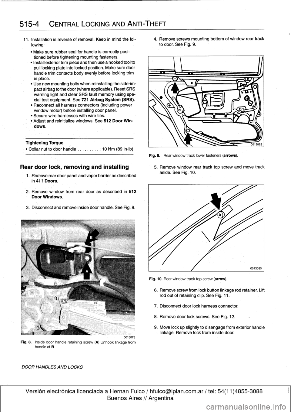
Fig
.
8
.
Inside
door
handle
retaining
screw
(A)
Unhook
linkage
from
handle
at
B
.
DOOR
HANDLES
AND
LOCKS
Fig
.
9
.
Rear
window
track
lower
fasteners
(arrows)
.
Reardoor
lock,
removing
and
installing
5
.
Remove
window
rear
track
top
screw
and
move
track
aside
.
See
Fig
.
10
.
Fig
.
10
.
Rear
window
track
top
screw
(arrow)
.
6
.
Remove
screw
from
lock
button
linkage
rod
retainer
.
Lift
rod
out
of
retaining
clip
.
See
Fig
.
11
.
7
.
Disconnect
door
lock
harnessconnector
.
8
.
Remove
door
lock
screws
.
See
Fig
.
12
.
0013085
9
.
Move
lock
upslightly
to
disengage
from
exterior
handle
linkage
.
Remove
lock
from
inside
door
.
Page 353 of 759
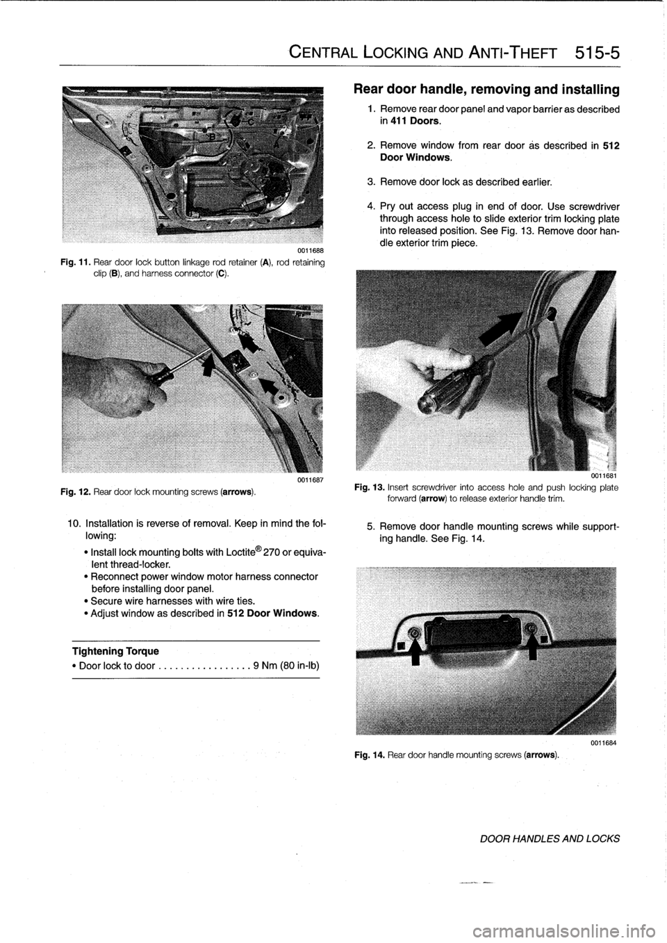
0011688
Fig
.
11
.
Rear
door
lockbutton
linkage
rod
retainer
(A),
rod
retaining
clip
(B),
and
harness
connector
(C)
.
Fig
.
12
.
Rear
door
lock
mounting
screws
(arrows)
.
0011687
10
.
Installation
is
reverse
of
removal
.
Keep
in
mind
the
fol-
lowing
:
"
Insta¡¡
lock
mounting
boits
with
Loctite
©
270
or
equiva-
lentthread-locker
.
"
Reconnect
power
window
motorharness
connector
before
installing
door
panel
.
"
Secure
wire
harnesses
with
wire
ties
.
"
Adjust
window
as
described
in
512
Door
Windows
.
Tightening
Torque
"
Door
lock
to
door
.
...
.
..
..........
9
Nm
(80
in-lb)
CENTRAL
LOCKING
AND
ANTI-THEFT
515-5
Rear
door
handie,
removing
and
installing
1
.
Remove
rear
door
panel
and
vapor
barrier
as
described
in
411
Doors
.
2
.
Remove
window
from
rear
door
as
described
in
512
Door
Windows
.
3
.
Remove
door
lock
as
described
earlier
.
4
.
Pry
out
access
plug
in
end
of
door
.
Use
screwdriver
through
access
hole
to
slide
exterior
trim
locking
plate
into
released
position
.
See
Fig
.
13
.
Remove
doorhan-
dle
exterior
trim
piece
.
u
.]lbbl
Fig
.
13
.
Insert
screwdriver
into
access
hole
and
push
locking
plate
forward
(arrow)torelease
exterior
handle
trim
.
5
.
Remove
door
handle
mountingscrews
while
support-
ing
handle
.
See
Fig
.
14
.
Fig
.
14
.
Reardoor
handle
mounting
screws
(arrows)
.
0011684
DOOR
HANDLES
AND
LOCKS
Page 354 of 759
515-6
CENTRAL
LOCKING
AND
ANTI-THEFT
6
.
Remove
door
handle
assembly
from
inside
door
.
7
.
Installation
is
reverse
of
removal
.
Keep
in
mindthe
fol-
lowing
:
"
Make
sure
rubber
seal
for
handle
is
correctly
posi-
tionedbefore
tightening
mounting
fasteners
.
"
Install
exterior
trim
piece
and
then
use
a
hooked
toolto
pull
locking
plate
into
locked
position
.
Make
sure
door
handle
trim
contacts
body
evenly
before
lockingtrim
in
place
.
"
Reconnect
all
harness
connectors
(including
power
window
motor)before
installing
door
panel
.
"
Secure
wire
harnesses
withwire
ties
.
"
Adjust
windowas
described
in
512
Door
Windows
.
Tightening
Torque
"
Rear
door
handle
mounting
screws
..
10
Nm
(89
in-lb)
NOTE
If
the
striker
backup
plate
fafls
into
the
body
cavlty,
it
can
be
retrieved
after
removing
the
inside
trim
from
the
B-pillar
(door-post
pillar)
.
Tightening
Torque
"
Striker
plate
to
body
pillar
..........
28
Nm
(20
ft-lb)
LOCKING
ACTUATORS
Door
Locking
Actuator
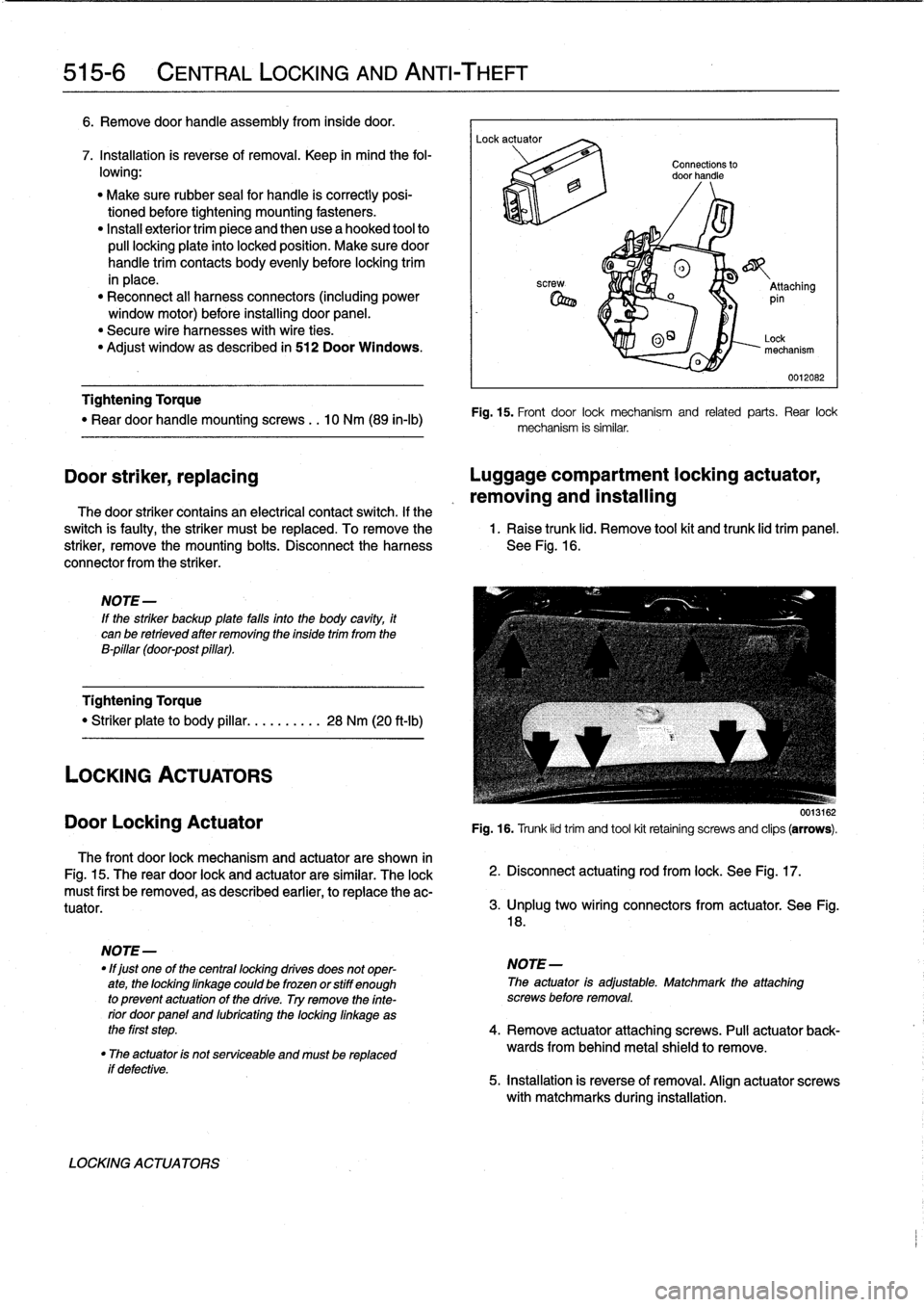
The
front
door
lock
mechanism
and
actuator
are
shown
in
Fig
.
15
.
The
rear
door
lock
and
actuator
are
similar
.
The
lock
must
first
be
removed,
as
described
earlier,
to
replace
the
ac-
tuator
.
if
defective
.
LOCKING
ACTUATORS
Connections
to
door
handle
®
o
_
Attaching
pin
0
O~
Lock
mechanism
0012082
Fig
.
15
.
Front
door
lock
mechanism
and
related
parts
.
Rear
lock
mechanism
is
similar
.
Door
striker,
replacing
Luggage
compartment
locking
actuator,
removing
and
installing
The
door
striker
contains
an
electrical
contact
switch
.
If
the
switch
is
faulty,
the
striker
must
be
replaced
.
To
remove
the
1
.
Raise
trunk
lid
.
Remove
tool
kit
and
trunk
lid
trim
panel
.
striker,
remove
the
mounting
bolts
.
Disconnect
the
harness
See
Fig
.
16
.
connector
from
the
striker
.
0013162
Fig
.
16
.
Trunk
lid
trim
and
tool
kit
retainíng
screws
and
clips
(arrows)
.
2
.
Disconnect
actuating
rod
from
lock
.
See
Fig
.
17
.
3
.
lJnplug
two
wíring
connectors
from
actuator
.
See
Fig
.
18
.
NOTE
-
"
lf
just
one
of
the
centrallocking
drives
does
not
oper-
NOTE-
ate,
the
lockinglinkage
could
be
frozen
orstiff
enough
The
actuator
is
adjustable
.
Matchmark
the
attaching
to
prevent
actuatonof
the
drive
.
Try
remove
the
finte-
screws
before
removal
.
rior
doorpanel
and
lubricating
the
locking
linkage
as
the
first
step
.
4
.
Remove
actuator
attaching
screws
.
Pull
actuator
back-
"
The
actuator
is
not
serviceable
and
mustbe
replaced
wards
from
behind
metal
shield
to
remove
.
5
.
installation
is
reverse
of
removal
.
Align
actuator
screws
with
matchmarks
during
installation
.
Page 371 of 759
GENERAL
.
...
.
.
.
......
.
.
.
.
.
.
.
.
.
......
541-1
Visor
Latch
Plate
.....
.
....
.
.
.
.
.
...
.
...
.541-4
Visor
Latch
..
.
............
.
.
.
..........
541-4
MANUAL
CONVERTIBLE
TOP
.
.
.
.
...
.
..
541-1
Visor
Latch
Motor
...
.......
.
.
.
..
........
541-5
Visor
Latch
Plate
.
.
......
.
.
.
...
.
.
.
.
.
.
.
..
541-1
Convertible
top
and
frame,
replacing
........
541-5
VisorLatch
.
.
.
.
.
.
.
.
..........
.
.....
.
.
.541-1
Convertible
top
drive
motor,
replacing
......
541-7
Convertible
Top
Lid
Release
Mechanism
.
.
.
.
541-2
Convertible
Top
Emergency
Operation
.....
.541-7
Convertible
top
and
frame,
replacing
....
.
.
.
541-2
Convertible
Top
Lid
.
.
.
.
...........
.
.....
541-9
POWER
CONVERTIBLE
TOP
.
.
.
.
....
.
.
.
541-2
ROLLOVER
PROTECTION
SYSTEM
..
.
.
541-9
FrontLatching
Mechanism
.
.
.
.
.
.
.
.
......
.
541-4
GENERAL
The
convertible
top
comes
in
three
versions
:
a
manually
op-erated
top,
a
semi-automatic
power
top
and
a
fully
automatic
power
top
.
NOTE-
The
convertible
top
control
module
(CVM)
is
located
behind
the
left
rearside
trim
panel
.
For
the
location
of
other
convertible
top
electric
components
see610
Electrical
Component
Locations
.
The
rear
window
in
the
convertible
models
is
made
of
a
strong,
flexible
vínyl
which
is
available
separately
.
Replace-
ment
of
the
rear
window
is
not
covered
in
this
manual
.
The
left
and
right
visor
latch
plates
can
be
accessed
by
re-
moving
the
trim
and
moldings
around
the
sides
and
top
of
the
windshield
.
Each
latch
is
secured
to
thetop
of
the
windshield
usingthree
bolts
.
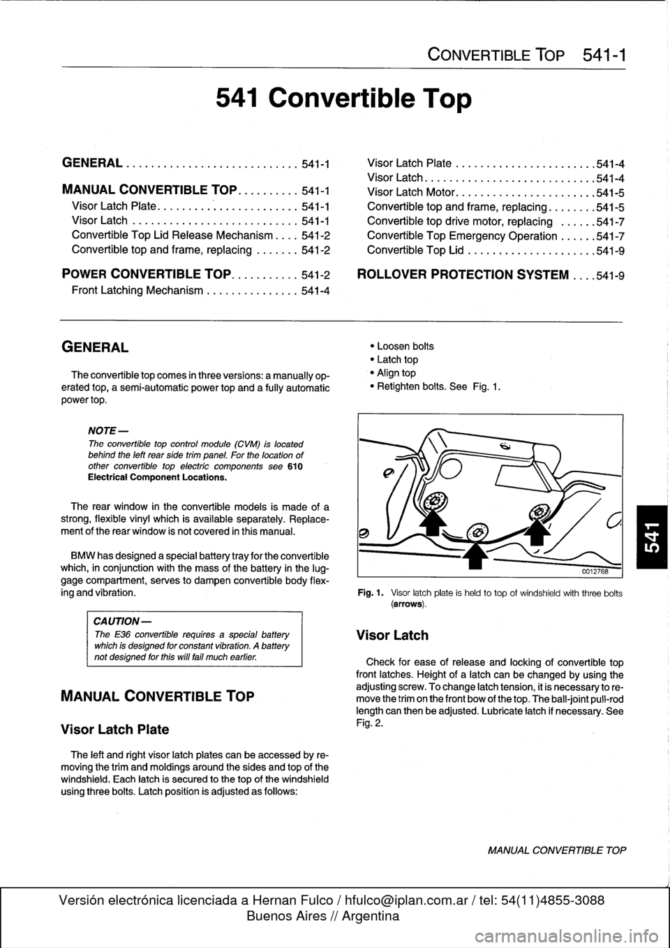
Latch
position
is
adjusted
as
follows
:
541
Convertible
Top
CONVERTIBLE
TOP
541-1
"
Loosen
bolts
"
Latch
top
"
Align
top
"
Retighten
bolts
.
See
Fig
.
1
.
BMW
has
designed
a
specialbattery
tray
for
the
convertible
which,
in
conjunction
with
the
mass
of
the
battery
in
the
lug-
gage
compartment,
serves
to
dampen
convertible
body
flex
ing
and
vibration
.
Fig
.
1.
Visor
latchplate
is
held
to
top
of
windshieldwith
three
bolts
(arrows)
.
CAUTION-
The
E36
convertible
requires
a
specialbattery
VisorLatch
which
is
designed
for
constant
vibration
.
A
battery
not
designed
forthis
will
fa¡¡
much
earlier
.
Check
for
ease
of
release
and
locking
of
convertible
top
front
latches
.
Height
of
a
latch
can
be
changed
by
using
the
adjusting
screw
.
To
change
latch
tension,
it
is
necessary
to
re-
MANUAL
CONVERTIBLE
TOP
move
the
trim
on
the
front
bow
of
thetop
.
The
ball-joint
pull-rod
length
can
then
be
adjusted
.
Lubricate
latch
if
necessary
.
See
Visor
Latch
Plate
Fig
.
2
.
MANUAL
CONVERTIBLE
TOP
Page 379 of 759
Convertible
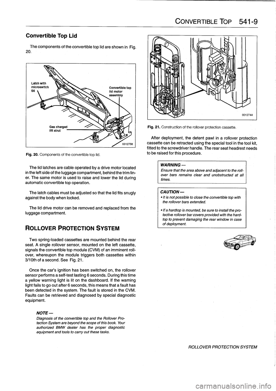
Top
Lid
The
components
of
the
convertible
top
lid
are
shown
in
Fig
.
20
.
Fig
.
20
.
Components
of
the
convertible
top
lid
.
ROLLOVER
PROTECTION
SYSTEM
The
lid
latches
are
cable
operated
by
a
drive
motor
located
in
the
left
sideof
the
luggagecompartment,
behind
the
trim
lin-
er
.
The
same
motor
is
used
to
raise
and
lower
the
lid
during
automatic
convertible
topoperation
.
The
latch
cables
must
be
adjusted
so
that
the
lidfits
snugly
against
the
body
when
locked
.
The
lid
drive
motor
can
be
removed
and
replaced
from
the
luggage
compartment
.
Two
spring-locaed
cassettes
are
mounted
behind
the
rear
seat
.
A
single
rollover
sensor,
mounted
on
the
left
cassette,
signals
the
convertible
top
module
(CVM)
of
animminent
roll-
over,
whereupon
the
module
triggers
both
cassettes
within
3j10th
of
a
second
.
See
Fig
.
21
.
Once
the
cars
ignition
has
been
switched
on,
the
rollover
sensor
performs
a
self-test
lasting
6
seconds
.
During
this
time
a
yellow
warning
light
is
lit
on
the
dashboard
.
If
thewarning
lightfails
to
go
out
after
6
seconds,
this
means
that
a
fault
has
been
detected
in
the
system
.
The
fault
is
stored
in
the
CM
Faults
canbe
retrieved
and
diagnosedby
special
diagnostic
equipment
.
NOTE-
Diagnosis
of
the
convertible
top
and
the
Rollover
Pro-
tection
System
are
beyond
the
scope
of
this
book
.
Your
authorized
BMW
dealer
has
the
proper
diagnostic
equipment
and
tools
to
carry
out
these
tasks
.
CONVERTIBLE
TOP
541-
9
Fig
.
21
.
Construction
of
the
rollover
protection
cassette
.
After
deployment,
thedetent
pawl
in
a
rollover
protection
cassette
can
be
retracted
using
the
special
tool
in
the
tool
kit,
fitted
to
the
screwdriver
handle
.
The
rear
seatheadrest
needs
to
be
raised
for
this
procedure
.
WARNING
-
Ensure
that
the
area
above
and
adjacent
to
the
roll-
over
bars
remains
clear
and
unobstructed
at
all
times
.
CAUTION-
"
Itis
not
possible
to
close
the
convertible
top
with
the
rollover
bars
extended
.
"
If
a
hardtop
is
mounted,
be
sure
to
install
the
pro-
tective
rollover
bar
covers
provided
with
the
hard-
top
to
prevent
damaglng
the
rear
window
in
case
of
deployment
.
0012744
ROLLOVER
PROTECTION
SYSTEM
Page 390 of 759
610-4
ELECTRICAL
COMPONENT
LOCATIONS
--J
L
Windshield
washertank
&
pump
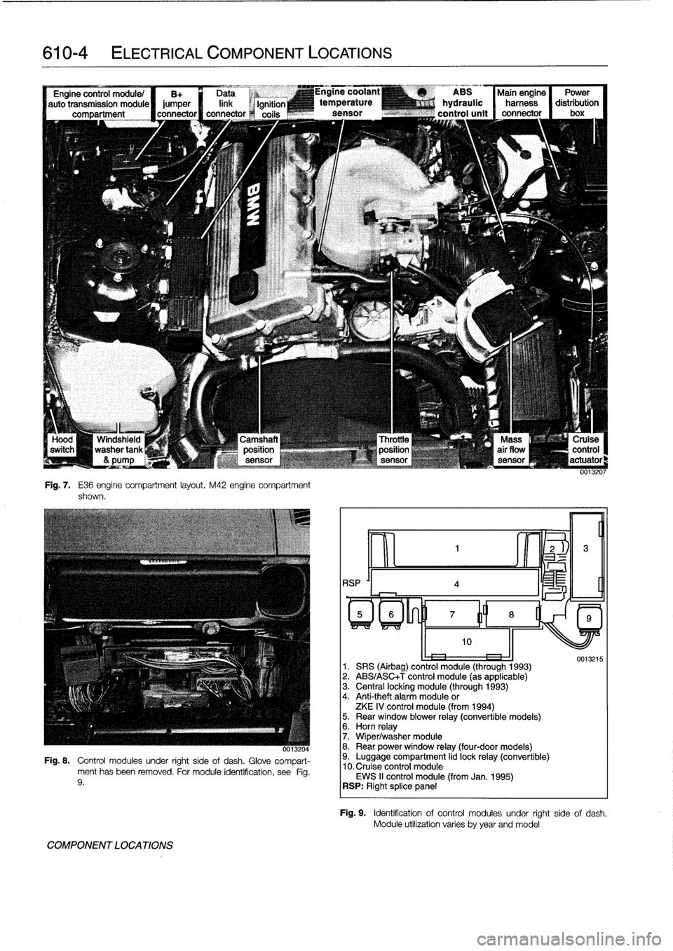
Fig
.
7
.
E36
engine
compartment
layout
.
M42
engine
compartment
shown
.
-,x
0013204
Fig
.
8
.
Control
modules
under
right
sideof
dash
.
Glove
compart-
ment
has
been
removed
.
For
module
identification,
see
Fig
.
9
.
COMPONENT
LOCATIONS
RSP
'I
4
ABS
Main
engine
Power
hydraulic
harness
distribution
control
unit
connector
I
box
oe
1
.
SRS
(Airbag)
control
module
(through
1993)
2
.
ABS/ASC+T
control
module
(as
applicable)
3
.
Central
locking
module
(through
1993)
4
.
Anti-theft
alarm
module
or
ZKE
IV
control
module
(from
1994)5
.
Rear
window
blower
relay
(convertible
models)6
.
Horn
relay
7
.
Wiper/washer
module
8
.
Rear
power
window
relay
(four-door
models)9
.
Luggage
compartment
lid
lock
relay
(convertible)
10
.
Cruise
control
module
EWS
II
control
module
(from
Jan
.
1995)
RSP
:
Right
splice
panel
0013215
Fig
.
9
.
Identificationof
control
modules
under
right
side
of
dash
.
Module
utilízation
varies
byyear
andmodel
Page 397 of 759
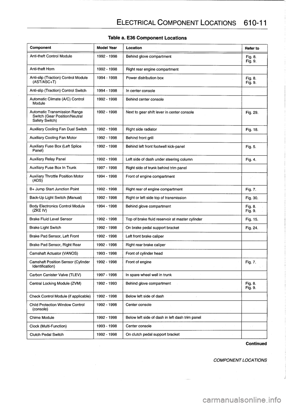
Table
a
.
E36
Component
Locations
Component
Model
Year
Location
Refer
to
Anti-theft
Control
Module
1992-1998
Behind
glove
compartment
Fig
.
8
.
Fig
.
9
.
Anti-theft
Horn
1
1992-1998
1
Right
rear
engine
compartment
Anti-slip
(Traction)
Control
Module
1994-1998
Power
distribution
box
Fig
.
8
.
(AST/ASC+T)
Fig
.
9
.
Anti-slip
(Traction)
Control
Switch
1994-1998
In
center
console
Automatic
Climate
(A/C)
Control
1992-1998
Behind
center
console
Module
AutomaticTransmission
Range
1992-1998
~
Next
to
gear
shift
lever
in
center
console
Fig
.
29
.
Switch
(Gear
Position/Neutral
Safety
Switch)
Auxiliary
Cooling
Fan
Dual
Switch
1992-1998
Right
side
radiator
1
Fig
.
18
.
Auxiliary
Cooling
Fan
Motor
1992-1998
Behind
front
grill
Auxiliary
Fuse
Box
(Left
Splice
1992-1998
I
Behind
left
front
footwell
kick-panel
Panel)
Auxiliary
RelayPanel
1
1992-1998
1
Left
side
of
dash
under
steering
column
Auxiliary
Fuse
Box
In
Trunk
1
1997-1998
1
Right
sideof
trunk
behind
trim
panel
AuADSry
ThrottlePosition
Motor
11994-1998
Front
of
engine
compartment
B+
Jump
Start
Junction
Point
1992-1998
Right
rear
of
engine
compartment
Fig
.
7
.
Back-Up
Light
Switch
(Manual)
1992-1998
Right
or
left
side
top
of
transmission
Fig
.
30
.
Body
Electronics
Control
Module
1994-1998
Behindglove
compartment
Fig
.
8
.
(ZKE
IV)
Fig
.
9
.
Brake
Fluid
Level
Sensor
1992-1998
Top
of
brake
fluid
reservoir
at
master
cylinder
Fig
.
15
.
Brake
Light
Switch
1
1992-1998
1
On
brake
pedal
supportbracket
Brake
Pad
Sensor,
Left
Front
1
1992-1998
1
Left
front
brake
caliper
Brake
Pad
Sensor,
Right
Rear
1992-1998
Right
rear
brake
caliper
Camshaft
Actuator
(VANOS)
1993-1998
Front
of
cylinder
head
Camshaft
Position
Sensor
(Cylinder
1992-1998
Front
of
engine
Identification)
Carbon
Canister
Valve
(TLEV)
1
1997-1998
1
In
sparewheel
well
in
trunk
ELECTRICAL
COMPONENT
LOCATIONS
610-11
Fig
.
5
.
Fig
.
4
.
Fig
.
24
.
Fig
.
7
.
Central
Locking
Module
(ZVM)
11992-1993
1
Behindglove
compartment
I
Fig
.
8
.
Fig
.
9
.
Check
Control
Module
(if
applicable)
1
1992
-
1998
1
Below
left
side
of
dash
Child
Protection
Window
Control
1992-1998
Center
console
(console)
Chime
Module
1992-1998
Below
left
side
of
dash
inleft
dash
trim
panel
Clock
(Multi-Function)
1993-1998
Center
console
Clutch
Pedal
Switch
1992-1998
On
clutch
pedal
support
bracket
Continued
COMPONENT
LOCATIONS