terminal 7 BMW 325i 1992 E36 Owner's Manual
[x] Cancel search | Manufacturer: BMW, Model Year: 1992, Model line: 325i, Model: BMW 325i 1992 E36Pages: 759
Page 138 of 759
121-2
BATTERY,
STARTER,
ALTERNATOR
CHARGING
SYSTEM
TROUBLESHOOTING
Static
currentdraw,
checking
Charging
system
diagnostics
requires
special
test
equip-
ment
.
If
the
test
equipment
is
not
available,
charging
system
fault
diagnosis
can
be
performedby
an
authorized
BMW
deal-
eror
other
qualified
repair
shop
.
A
general
troubleshooting
guide
is
given
in
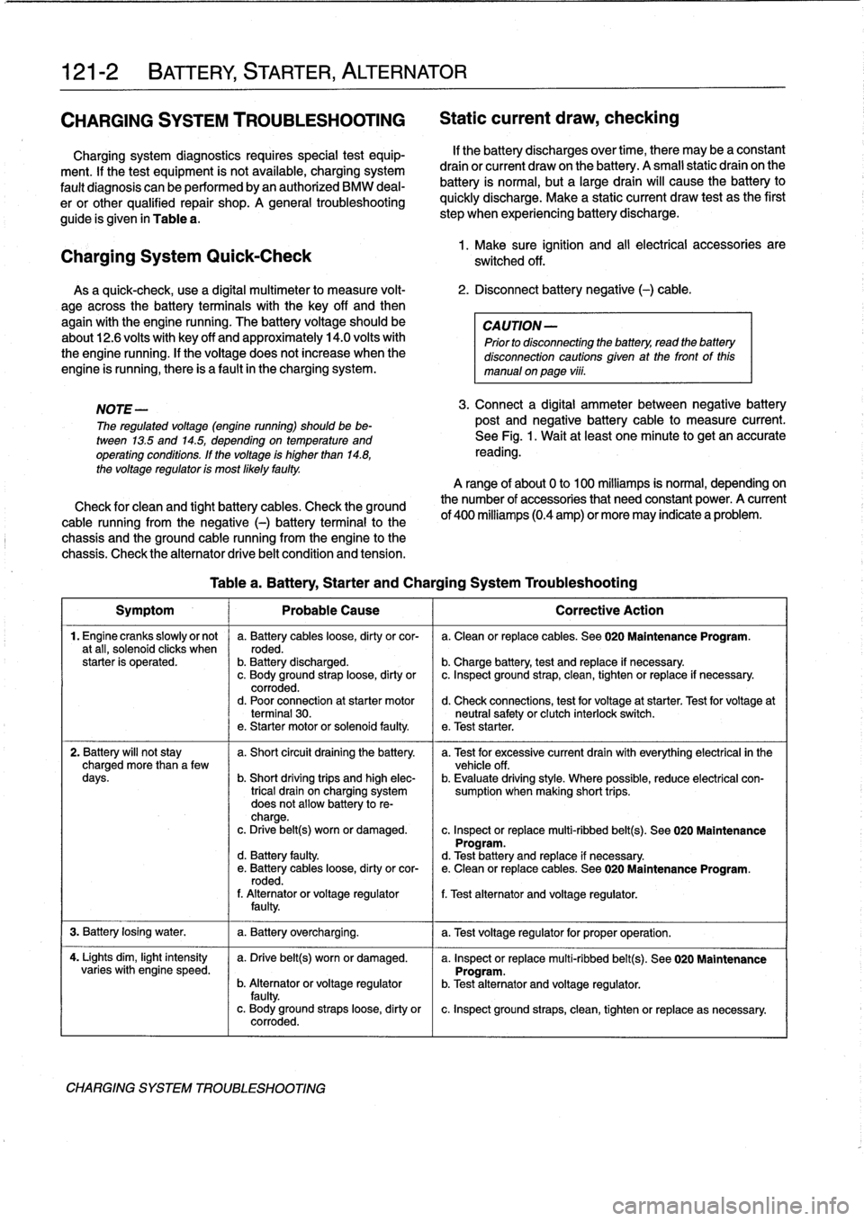
Table
a
.
Charging
System
Quick-Check
As
a
quick-check,
use
a
digital
multimeter
lo
measure
volt-
2
.
Disconnect
battery
negative
(-)
cable
.
age
across
the
battery
terminals
with
the
key
off
and
then
again
with
the
engine
running
.
The
battery
voltage
should
be
CAUTION-
about12
.6
volts
with
key
off
and
approximately
14
.0
volts
with
Prior
to
disconnecting
the
battery,
read
the
battery
the
engine
running
.
If
the
voltage
does
not
increase
when
the
disconnection
cautions
given
at
the
front
of
this
engine
is
running,there
is
a
fault
in
the
charging
system
.
manual
onpaga
viii
.
NOTE
-
The
regulated
voltage
(engine
running)
should
be
be-
tween
13
.5
and
14
.5,
depending
on
temperatura
and
operating
conditions
.
If
the
voltage
is
higher
than
14
.8,
the
voltage
regulator
is
most
Mely
faulty
.
Check
for
clean
and
tight
battery
cables
.
Check
the
ground
cable
running
from
the
negative
(-)
battery
terminal
lo
the
chassis
and
the
ground
cable
running
from
the
engine
lo
the
chassis
.
Check
the
alternator
drive
belt
condition
and
tension
.
If
the
battery
discharges
over
time,
there
may
be
a
constant
drain
or
current
draw
on
the
battery
.
A
small
static
drain
on
the
battery
is
normal,
but
a
largedrain
will
cause
the
battery
lo
quickly
discharge
.
Make
a
static
current
draw
test
asthe
first
step
when
experiencing
battery
discharge
.
1
.
Make
sure
ignition
and
al¡
electrical
accessories
are
switched
off
.
3
.
Connect
a
digital
ammeter
between
negative
battery
post
and
negative
battery
cable
lo
measure
current
.
See
Fig
.
1
.
Wait
at
least
one
minuta
lo
get
an
accurate
reading
.
A
range
of
about
0
lo
100
milliamps
is
normal,
dependingon
the
number
of
accessories
that
need
constant
power
.
A
current
of
400
milliamps
(0.4
amp)
or
more
may
indicate
a
problem
.
Table
a
.
Battery,
Starter
and
Charging
System
Troubleshooting
Symptom
1
Probable
Cause
1
Correctiva
Action
1
.
Engine
cranks
slowlyor
not
a
.
Battery
cables
loose,
dirty
orcor-
a
.
Clean
or
replace
cables
.
See020
Maintenance
Program
.
a
tall,
solenoíd
clicks
when
roded
.
starter
is
operated
.
b
.
Battery
discharged
.
b
.
Charge
battery,
test
and
replace
if
necessary
.
c
.
Body
ground
straploose,
dirty
or
c
.
Inspect
ground
strap,
clean,
tighten
or
replace
if
necessary
.
corroded
.
d
.
Poor
connection
at
starter
motor
d
.
Check
connections,
test
for
voltage
at
starter
.
Test
for
voltage
at
terminal
30
.
neutral
safety
or
clutch
interlock
switch
.
e
.
Starter
motor
or
solenoid
faulty
.
e
.
Test
starter
.
2
.
Battery
will
not
stay
a
.
Short
circuit
draining
the
battery
.
a
.
Test
for
excessive
current
drainwith
everything
electrical
in
the
charged
more
than
a
few
vehicle
off
.
days
.
b
.
Short
driving
trips
and
high
elec-
b
.
Evaluate
driving
style
.
Where
possible,
reduce
electrical
con
trical
drain
on
charging
system
sumption
when
making
short
trips
.
does
not
allow
battery
to
re-
charge
.
c
.
Drive
belt(s)
worn
or
damaged
.
c
.
Inspect
or
replace
multi-ribbed
belt(s)
.
See
020
Maintenance
Program
.
d
.
Battery
faulty
.
d
.
Test
battery
and
replace
íf
necessary
.
e
.
Battery
cables
loose,
dirty
orcor-
e
.
Clean
or
replace
cables
.
See
020
Maintenance
Program
.
rodad
.
f
.
Alternatoror
voltage
regulator
f
.
Test
alternator
and
voltage
regulator
.
faulty
.
3
.
Battery
losing
water
.
1
a
.
Battery
overcharging
.
1
a
.
Test
voltage
regulator
for
proper
operation
.
4
.
Lights
dim,
light
intensity
a
.
Drive
belt(s)
worn
or
damaged
.
a
.
Inspect
or
replace
multi-ribbed
belt(s)
.
See
020
Maintenance
varies
with
engine
speed
.
Program
.
b
.
Alternatoror
voltage
regulator
b
.
Test
alternator
and
voltage
regulator
.
faulty
.
c
.
Body
ground
straps
loose,
dirty
or
c
.
Inspect
ground
straps,
clean,
tighten
or
replace
as
necessary
.
corroded
.
CHARGING
SYSTEM
TROUBLESHOOTING
Page 140 of 759
121-
4
BATTERY,
STARTER,
ALTERNATOR
BatteryOpen-Circuit
Voltage
Test
Battery
Charging
Before
making
the
test,
load
the
battery
with
15
amperes
for
Discharged
batteries
can
be
recharged
using
a
battery
one
minute
with
a
batteryload-tester
or
turn
on
the
headlights
charger
.
The
battery
should
be
removed
from
the
luggage
for
about
one
minute
without
the
engine
running
.Then
discon-
compartment
during
charging
.
nect
the
battery
negative
(-)
cable
and
connect
a
digital
volt-
meter
acrossthe
battery
terminals
.
Open-circuit
voltage
Prolonged
charging
causes
electrolyte
evaporation
to
a
lev
levels
are
given
in
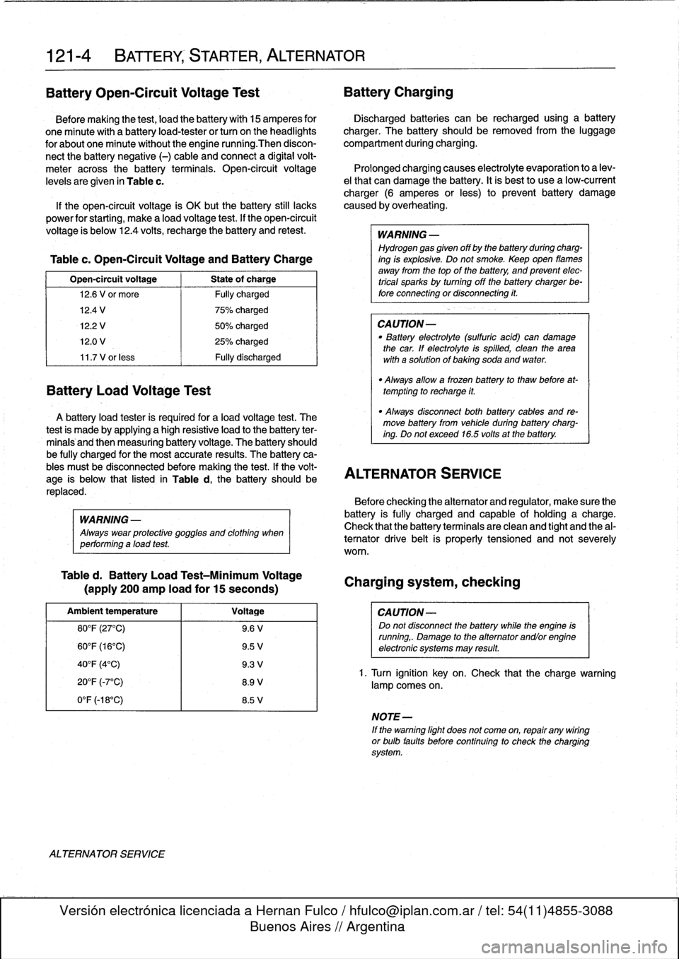
Table
c
.
el
that
can
damage
the
battery
.
Itis
bestto
use
a
low-current
charger
(6
amperes
or
less)
to
prevent
battery
damage
If
the
open-circuit
voltage
ís
OK
butthe
battery
still
lacks
caused
by
overheating
.
power
for
starting,
make
a
load
voltage
test
.
If
the
open-circuit
voltage
is
below
12
.4
volts,
recharge
the
battery
and
retest
.
WARNING
-
Hydrogen
gas
given
off
by
the
battery
duringcharg-
Table
c
.
Open-Circuit
Voltage
and
Battery
Charge
ing
is
explosive
.
Do
not
smoke
.
Keep
open
llames
away
from
the
top
of
the
battery,
and
prevent
elec
Open-circuit
voltage
State
of
charge
trical
sparks
by
turning
offthe
battery
charger
be-
12
.6
V
or
more
Fully
charged
fore
connecting
or
disconnecting
it
.
12
.4
V
1
75%
charged
12
.2
V
50%
charged
CAUTION-
12
.0
V
25%
charged
"
Battery
electrolyte
(sulfuric
acid)
can
damage
the
car
.
If
electrolyte
isspilled,
clean
the
area
11
.7
V
or
less
Fully
discharged
with
a
solution
of
baking
soda
and
water
.
Battery
Load
Voltage
Test
A
battery
load
tester
is
required
for
a
load
voltage
test
.
The
-
Always
disconnect
both
battery
cables
and
re-
test
is
made
by
applying
a
high
resistive
load
to
the
battery
ter-
move
battery
from
vehicle
during
battery
charg-
ing
.
Do
not
exceed
16
.5volts
at
the
battery
.
minals
and
then
measuring
battery
voltage
.
The
battery
should
be
fully
charged
for
the
most
accurate
results
.
The
battery
ca-
bles
mustbe
disconnected
before
making
the
test
.
If
the
volt-
ALTERNATOR
$ERVICE
age
is
below
that
listed
in
Table
d,
the
battery
should
be
replaced
.
WARNING
-
Always
wear
protective
goggles
and
clothing
when
performing
aload
test
.
Table
d
.
Battery
Load
Test-Minimum
Voltage
(apply
200
amp
load
for
15
seconds)
Ambient
temperature
Voltage
80°F
(27°C)
9
.6
V
60°F
(16°C)
9
.5
V
40°F
(4°C)
9
.3
V
20°F
(-7°C)
8
.9
V
0°F
(-18°C)
8
.5
V
ALTERNATOR
SERVICE
"
Always
allow
a
frozen
battery
to
thaw
before
at-
tempting
to
recharge
it
.
Before
checking
the
alternator
and
regulator,
make
sure
the
battery
is
fully
charged
and
capable
of
holding
acharge
.
Check
that
the
battery
terminals
are
clean
and
tight
and
the
al-
ternator
drive
belt
is
properly
tensioned
and
not
severely
worn
.
Charging
system,
checking
CAUTION-
Do
not
disconnect
the
battery
while
the
engine
is
running,
.
Damage
to
the
alternator
andlorengine
electronic
systems
may
result
.
1.
Turn
ignition
key
on
.
Check
that
the
chargewarning
lamp
comes
on
.
NOTE-
If
the
warning
light
does
not
come
on,
repair
any
wiring
or
bulb
faults
before
continuing
to
check
the
charging
system
.
Page 141 of 759
2
.
Remove
cooling
duct
or
terminal
cover
from
rear
of
al-
2
.
Remove
air
cleaner
upper
section
with
mass
air
flow
ternator
.
sensor
.
3
.
Check
for
battery
voltage
between
ground
and
terminal
3
.
Remove
terminal
cover
from
rear
of
alternator
.
Discon
B+
at
back
of
alternator
.
Then
turn
ignition
on
and
nect
wiring
.
check
for
battery
voltage
between
terminal
D+
and
ground
.
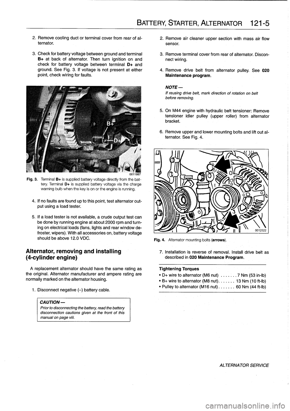
See
Fig
.
3
.
lf
voltage
is
not
present
at
either
4
.
Remove
drive
belt
from
alternator
pulley
.
See
020
point,
check
wiring
for
faults
.
Maintenance
program
.
001
¡987
Fig
.
3
.
Terminal
B+
is
supplied
battery
voltage
directly
from
the
bat-
tery
.
Terminal
D+
is
supplied
battery
voltage
via
the
charge
warning
bulb
when
thekey
is
on
or
the
engine
is
running
.
4
.
lf
no
faults
are
foundup
to
thispoint,test
alternator
out-
put
using
a
load
tester
.
5
.
If
a
load
tester
is
not
available,
a
crude
output
test
can
be
done
by
running
engine
at
about
2000
rpmand
turn-
ing
on
electrical
loads
(fans,
lights
and
rear
window
de-
froster,
wipers)
.
With
al¡
accessories
on,
battery
voltage
should
be
above
12
.0
VDC
.
A
replacement
alternator
should
have
the
same
rating
as
the
original
.
Alternator
manufacturer
and
ampere
rating
are
normally
marked
on
the
alternator
housing
.
1
.
Disconnect
negative
(-)
battery
cable
.
CAUTION-
Prior
to
disconnecting
the
battery,
read
the
battery
disconnection
cautions
given
at
the
front
of
this
manual
on
page
vi¡¡
.
BATTERY,
STARTER,
ALTERNATOR
121-
5
6
.
Remove
upper
and
lower
mounting
bolts
and
lift
out
al-
ternator
.
See
Fig
.
4
.
NOTE
-
If
reusing
drive
belt,
mark
direction
of
rotation
on
belt
before
removing
.
5
.
On
M44
engine
with
hydraulic
belt
tensioner
:
Remove
tensioner
idler
pulley
(upper
roller)
from
alternator
bracket
.
Fig
.
4
.
Alternator
mounting
bolts
(arrows)
.
O
u
J
S
v~~
U
I
1
i
n
-12
.22
Alternator,
removing
and
installing
7
.
Installation
is
reverse
of
removal
.
Install
drive
belt
as
(4-cylinder
engine)
described
in
020
Maintenance
Program
.
Tightening
Torques
"
D+
vire
to
alternator
(M6
nut)
.
...
.
.
.
7
Nm
(53
in-lb)
"
B+
wire
to
alternator
(M8
nut)
..
.
.
.
.
.
13
Nm
(10
ft-Ib)
"
Pulley
to
alternator
(M16
nut)
...
..
..
60
Nm
(44
ft-Ib)
ALTERNATOR
SERVICE
Page 143 of 759
Alternator
brushes,
STARTER
SERVICE
inspecting
and
replacing
Regulator
brushesarenot
available
as
replacement
parts
from
BMW
.
Replacement
brushes
may
be
available
from
af-
termarket
sources,
however
.
1
.
Remove
voltage
regulator
as
described
above
.
2
.
Clean
brush
contact
sürfaces
and
measure
brush
pro-trusion
.
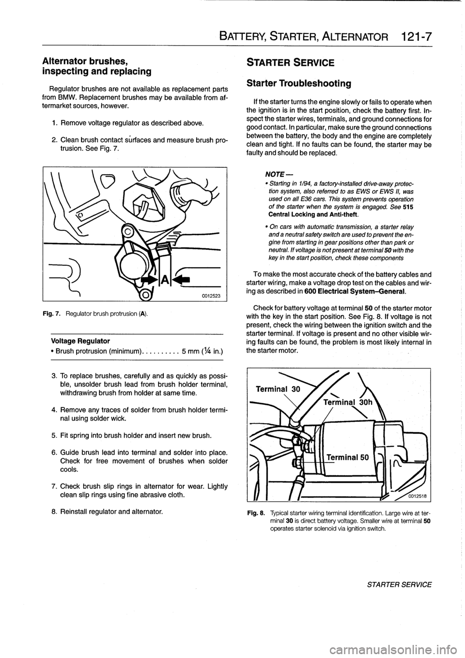
See
Fig
.
7
.
Check
for
battery
voltage
at
terminal
50
of
the
starter
motor
Fig
.
7
.
Regulator
brush
protrusion
(A)
.
with
the
key
in
the
start
position
.
See
Fig
.
8
.
If
voltage
is
not
present,
check
the
wiring
between
the
ignition
switch
and
the
starter
terminal
.
If
voltage
is
present
and
no
other
visible
wir
Voltage
Regulator
ing
faults
can
be
found,
the
problem
is
most
likely
interna¡in
"
Brush
protrusion
(minimum)
.......
.
..
5
mm
(
1
/4
in
.)
the
starter
motor
.
3
.
To
replace
brushes,
carefully
and
as
quickly
as
possi-
ble,
unsolder
brush
lead
from
brush
holder
termina¡,
withdrawing
brush
from
holder
at
same
time
.
4
.
Remove
any
traces
of
solder
frombrush
holder
termi-
nal
using
solder
wick
.
5
.
Fit
spring
into
brush
holder
and
inserí
new
brush
.
6
.
Guide
brush
lead
into
terminal
and
solder
into
place
.
Check
for
free
movement
of
brushes
when
solder
cools
.
7
.
Check
brush
slip
rings
in
alternator
for
wear
.
Lightly
clean
slip
rings
using
fine
abrasive
cloth
.
BATTERY,
STARTER,
ALTERNATOR
121-
7
Starter
Troubleshooting
If
the
starter
tucos
the
engine
slowlyor
fails
to
operate
when
the
ignition
isin
the
start
position,
check
the
battery
first
.
In-
spect
the
starter
wires,
terminals,
and
ground
connections
for
good
contact
.
In
particular,
make
sure
the
ground
connections
between
the
battery,
the
body
and
the
engine
are
completely
clean
and
tight
.
If
no
faults
can
be
found,
the
starter
may
be
faulty
and
should
be
replaced
.
NOTE
-
"
Starting
in1194,
a
factory-installed
drive-away
protec-
tion
system,
alsoreferred
to
as
EWS
or
EWS
11,
was
used
on
all
E36
cars
.
This
system
prevenís
operation
of
the
starter
when
the
system
is
engaged
.
See
515
Central
Locking
and
Anti-theft
.
"
On
cars
with
automatic
transmission,
a
starter
relay
and
a
neutral
safetyswitchare
used
to
present
theen-
ginefrom
starting
in
gear
positions
other
than
park
or
neutral
.
ff
voltage
is
not
present
atterminal
50
with
the
key
in
the
startposition,
check
these
components
To
make
the
most
accurate
check
of
the
battery
cables
and
starterwiring,
make
a
voltage
drop
test
on
the
cables
and
wir-
ing
as
described
in
600
Electrical
System-General
.
Terminal
30
'
\
/
Terminal
30h
0012518
8
.
Reinstall
regulator
and
alternator
.
Fig
.
8
.
Typical
starterwiring
terminal
identification
.
Large
wireat
ter-
minal
30
is
direct
battery
voltage
.
Smaller
wire
at
terminal
50
operates
starter
solenoid
via
ignition
switch
.
STARTER
SERVICE
Page 144 of 759
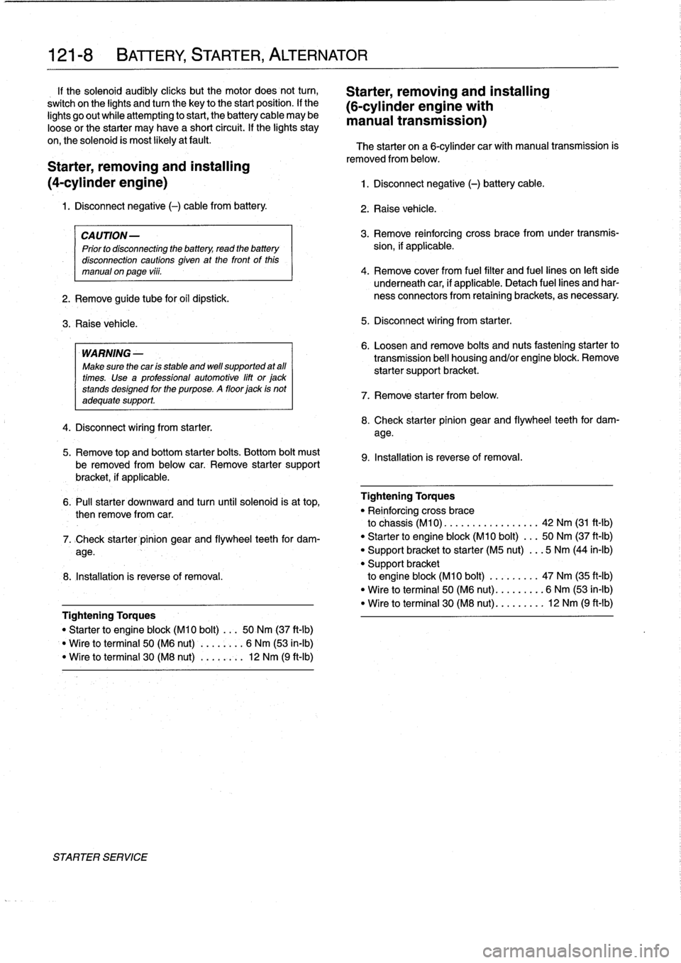
121-
8
BATTERY,
STARTER,
ALTERNATOR
1f
the
solenoid
audibly
cliicks
but
the
motor
does
not
turn,
Starter,
removing
and
installing
switch
on
the
lights
andtum
the
key
to
the
start
position
.
lf
the
(6-cylinder
engine
with
lights
go
out
while
attempting
to
start,
the
battery
cable
may
be
manual
transmission)
loose
or
the
starter
may
have
a
short
circuit
.
If
the
lights
stay
on,the
solenoid
is
most
likely
atfault
.
The
starter
on
a
6-cylinder
car
with
manual
transmission
is
Starter,
removing
and
installing
(4-cylinder
engine)
1
.
Disconnect
negative
(-)
battery
cable
.
1
.
Disconnect
negative
(-)
cable
from
battery
.
CAUTION-
Prior
to
disconnecting
the
battery,
read
the
battery
disconnection
cautions
given
at
the
front
of
this
manual
on
page
viii
.
2
.
Remove
guide
tube
for
oil
dipstick
.
3
.
Raise
vehicle
.
WARNING
-
Make
sure
the
car
ís
stable
and
wefl
supported
at
all
times
.
Use
a
professional
automotive
lift
or
jack
stands
designed
forthe
purpose
.
A
floor
jack
is
not
adequate
support
.
4
.
Disconnect
wiring
from
starter
.
5
.
Remove
top
and
bottom
starter
bolts
.
Bottom
bolt
must
be
removed
from
below
car
.
Remove
starter
support
bracket,
if
applicable
.
removed
from
below
.
2
.
Raise
vehicle
.
3
.
Remove
reinforcing
cross
bracefromunder
transmís-
sion,
if
applicable
.
4
.
Remove
cover
from
fuel
filter
and
fuel
lines
on
left
side
underneath
car,
if
applicable
.
Detach
fuel
lines
and
har-
ness
connectors
from
retainingbrackets,
as
necessary
5
.
Disconnect
wiring
from
starter
.
6
.
Loosen
andremove
bolts
and
nuts
fastening
starter
to
transmission
bell
housing
and/or
engine
block
.
Remove
starter
supportbracket
.
7
.
Remove
starter
from
below
.
8
.
Check
starter
pinion
gear
and
flywheel
teeth
for
dam-
age
.
9
.
Installation
is
reverse
of
removal
.
6
.
Pull
starter
downward
and
turn
until
solenoid
is
at
top,
Tightening
Torques
then
remove
from
car
.
"
Re¡
nforcing
cross
brace
to
chassis
(M10)
..
...............
42
Nm
(31
ft-Ib)
7
.
>Check
starter
pinion
gear
and
flywheel
teeth
for
dam-
"
Starter
to
engine
block
(M10
bolt)
...
50
Nm
(37
ft-Ib)
age
.
"
Support
bracket
to
starter
(M5
nut)
...
5
Nm
(44
in-lb)
"
Support
bracket
8
.
Installation
is
reverse
of
removal
.
to
engine
block
(M10
bolt)
.........
47
Nm
(35
ft-Ib)
"
Wire
to
terminal
50
(M6
nut)
.........
6
Nm
(53
ín-Ib)
"
Wire
to
terminal
30
(M8
nut)
.........
12
Nm
(9
ft-lb)
Tightening
Torques
"
Starter
to
engine
block
(M10
bolt)
...
50
Nm
(37
ft-lb)
Wire
to
terminal
50
(M6
nut)
........
6
Nm
(53
in-lb)
"
Wire
toterminal
30
(M8
nut)
...
,
..:.
12
Nm
(9
ft-Ib)
STARTER
SERVICE
Page 145 of 759
Starter,
removing
and
installing
(6-cylinder
engine
with
automatic
transmission)
The
starter
on
a
6-cylinder
car
with
automatic
transmission
ís
removed
from
above
.
It
is
necessary
to
remove
the
íntake
manifold
and
disconnect
a
number
of
electrical
harness
con-
nectors
.
1
.
Disconnect
negative
(-)
battery
cable
.
2
.
Remove
air
plenum
from
rear
of
engine
compartment
.
See640
Heating
and
Air
Conditioning
.
3
.
Remove
top
enginecovers
.
See
Fig
.
9
.
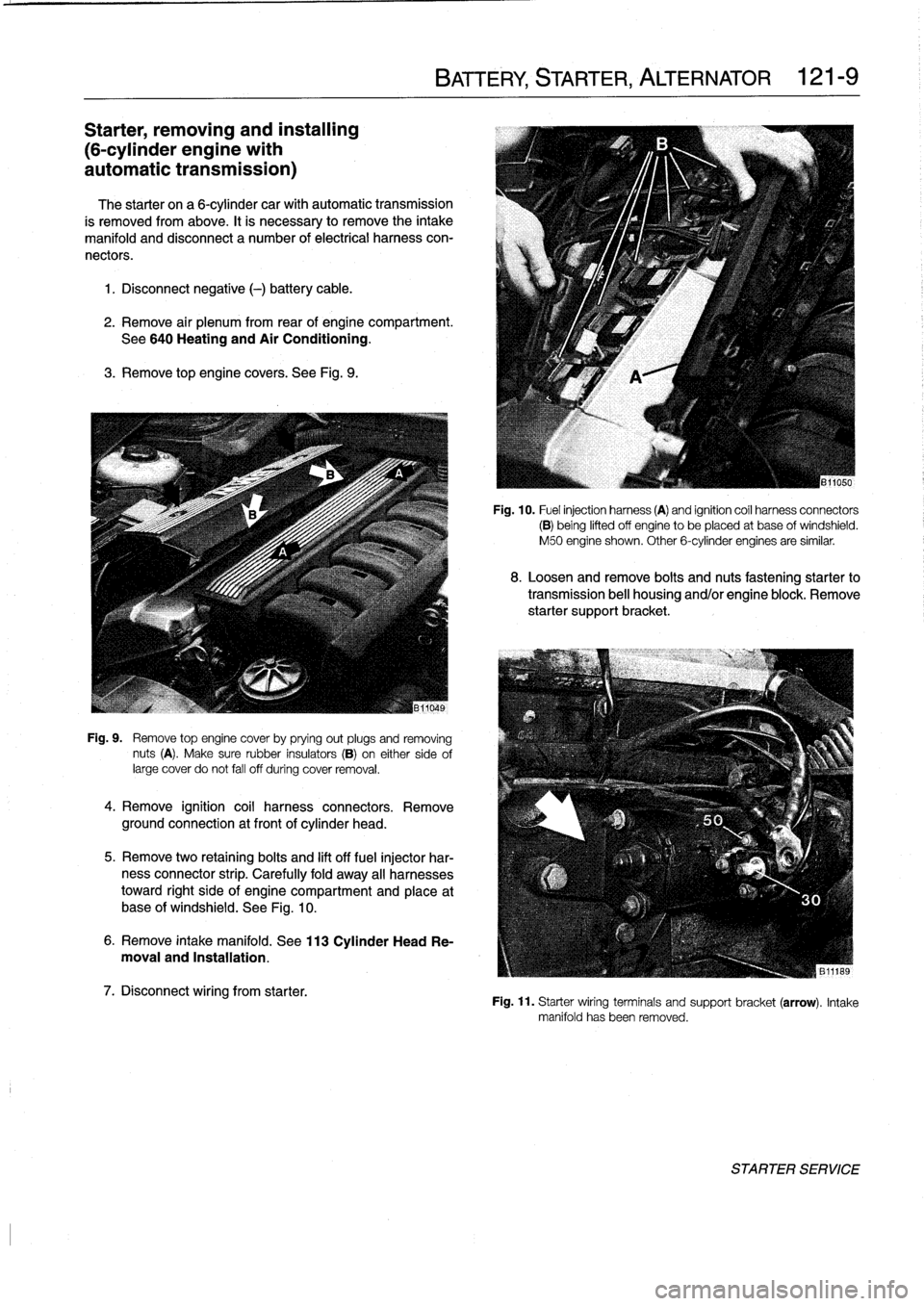
Fig
.
9
.
Remove
top
engine
cover
by
prying
out
plugs
and
removing
nuts
(A)
.
Make
sure
rubber
insulators
(B)
on
either
sideof
large
cover
do
not
fall
off
during
cover
removal
.
4
.
Remove
ignition
coil
harness
connectors
.
Remove
ground
connection
at
front
of
cylinder
head
.
5
.
Remove
two
retaining
bolts
and
lift
off
fuel
injector
har-
ness
connector
strip
.
Carefully
fold
away
all
harnesses
toward
right
side
of
engine
compartment
and
place
at
base
of
windshield
.
See
Fig
.
10
.
6
.
Remove
intake
manifold
.
See
113
Cylinder
Head
Re-
moval
and
Installation
.
7
.
Disconnect
wiring
from
starter
.
BATTERY,
STARTER,
ALTERNATOR
121-
9
Fig
.
10
.
Fuel
injection
harness
(A)
and
ignition
coíl
harness
connectors
(B)
being
lifted
off
engine
to
be
placed
at
base
ofwindshield
.
M50
engine
shown
.
Other
6-cylinder
engines
are
similar
.
8
.
Loosen
and
remove
bolts
and
nuts
fastening
starter
to
transmission
bell
housing
and/or
engine
block
.
Remove
starter
support
bracket
.
Fig
.
11
.
Starter
wiring
terminals
and
support
bracket(arrow)
.
Intake
manifold
has
been
removed
.
STARTER
SERVICE
Page 146 of 759
121-1
O
BATTERY,
STARTER,
ALTERNATOR
9
.
Remove
starter
from
above
.
10
.
Check
starter
pinion
gear
and
flywheel
teeth
for
dam-
age
.
11
.
Installation
is
reverse
of
removal
.
Tightening
Torques
"
tntakemanifold
to
cylinder
head
M7
nut
...
.
................
...
.
15
Nm
(11
ft-Ib)
M8
nut/bolt
.............
.
.
..
...
22
Nm
(16
ft-Ib)
"
Starter
to
engine
block
(M10
bolt)
...
50
Nm
(37
ft-Ib)
"
Support
bracket
to
starter
(M5
nut)
...
5
Nm
(44
in-lb)
"
Support
bracket
to
engine
block
(M10
bolt)
.
.
..
..
...
47
Nm
(35
ft-Ib)
"
Wire
toterminal
50
(M6
nut)
.
..
.....
6
Nm
(53
in-lb)
"
Wire
toterminal
30
(M8
nut)
...
.....
12
Nm
(9
ft-Ib)
Solenoid
switch,
removing
and
installing
1
.
Remove
starter
as
described
above
.
Tightening
Torque
2
.
Remove
cover
from
solenoid
switch
.
"
Field
winding
strap
to
starter
(M8)
...
.
12
Nm
(9
ft-Ib)
3
.
Disconnect
fieid
winding
strap
between
starter
motor
and
solenoid
switch
.
NOTE-
The
condition
of
the
field
winding
strap
is
critical
.
If
it
is
damaged,
bumed
or
partially
melted
through,
a
new
or
rebuilt
starter
motor
is
needed
.
4
.
Remove
solenoidswitch
mounting
screws,
and
sepa-
,
rate
solenoid
from
starter
.
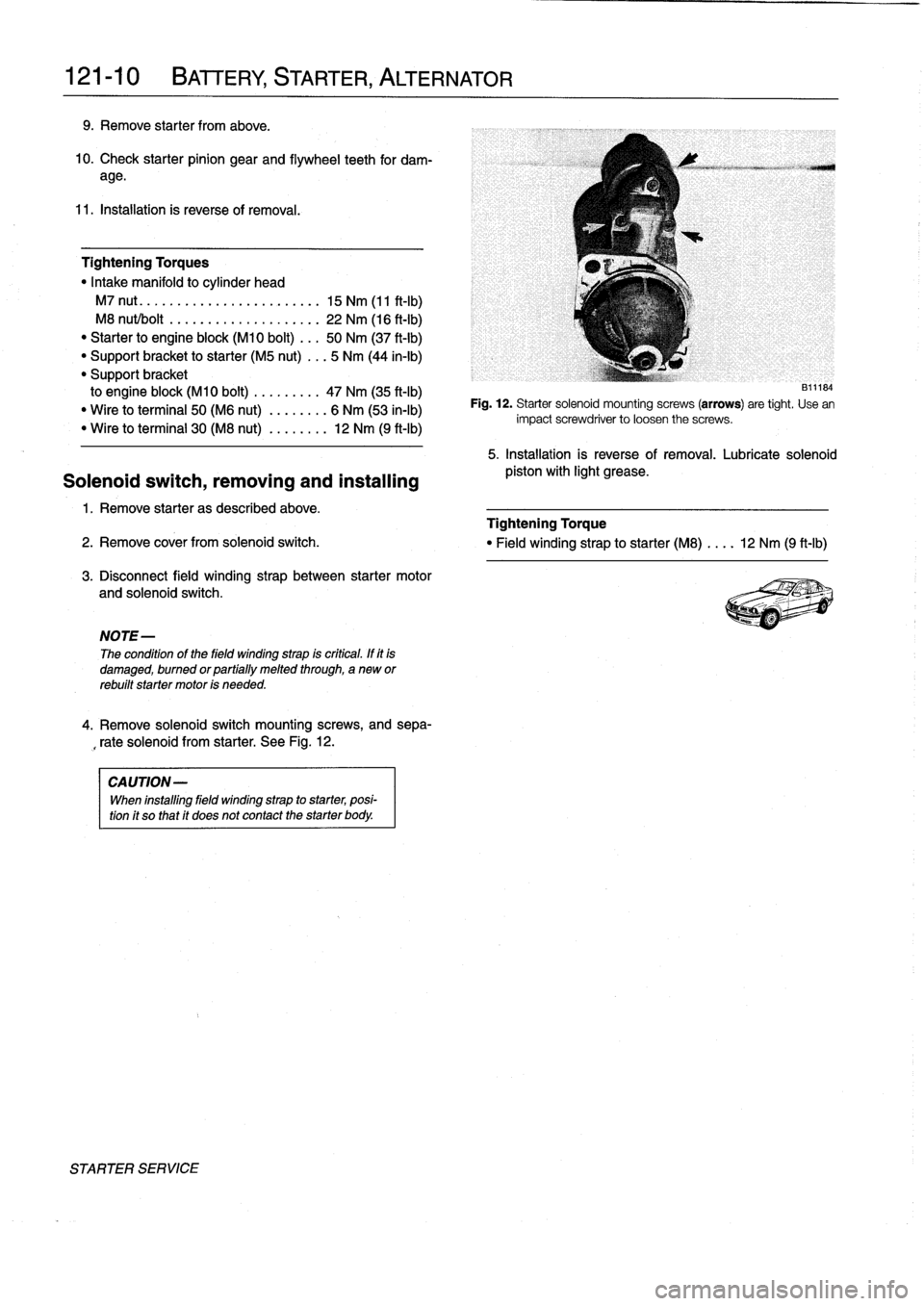
See
Fig
.
12
.
CAUTION-
When
installing
fieid
winding
strap
to
starter,
posi-
tion
it
so
that
it
does
not
contact
the
starter
body
.
STARTER
SERVICE
131~184
Fig
.
12
.
Starter
solenoid
mounting
screws
(arrows)
are
tight
.
Use
en
impact
screwdriver
to
loosen
the
screws
.
5
.
Installation
is
reverse
of
removal
.
Lubricate
solenoid
pistos
with
light
grease
.
Page 152 of 759
130-
6
FUEL
INJECTION
Warnings
and
Cautions
For
personal
safety,
as
well
as
the
protection
of
sensitive
electronic
components,
the
following
warnings
and
cautions
should
be
adhered
to
when
working
on
the
engine
manage-
ment
system
.
GENERAL
WARNING
-
"
The
ignition
system
produces
high
voltages
that
can
be
fatal
.
Avoid
contact
with
exposed
termi-
nals
.
Use
extreme
caution
when
working
onacar
with
the
ignition
switched
on
or
the
engine
run-
ning
.
"
Do
not
touch
or
disconnect
any
high
voltage
ca-
bles
from
the
coils
or
spark
plugs
while
the
engine
is
running
or
beingcranked
by
the
starter
.
"
Connect
and
disconnect
the
DME
system
wiring
and
test
equipment
leads
only
when
the
ignition
is
switched
off
.
"
Gasoline
is
highly
flammable
and
fts
vaporsare
explosive
.
Do
not
smoke
or
work
on
a
car
near
heaters
or
other
fire
hazards
when
diagnosing
and
repalring
fuel
system
problems
.
Have
a
tire
extinguisher
avaílable
in
case
of
an
emergency
.
"
When
working
onan
open
fuel
system,
wear
suit-
able
hand
protection,
asprolonged
contact
wfth
fuel
can
cause
illnesses
and
skin
disorders
.
"
Renew
fuel
system
hoses,
clamps
and
O-rings
any
timethey
are
removed
.
"
Before
makingany
electrical
tests
that
require
the
engine
to
be
cranked
using
the
starter,
disable
the
ignition
system
as
described
in
120
Ignition
System
.
CAUTION-
"
Prior
to
disconnecting
the
battery,
read
the
bat-
tery
disconnectinn
cautions
given
at
the
front
of
this
manual
onpage
vifi
.
"
Do
not
connect
any
test
equipment
that
delivers
a
12-volt
power
supply
to
terminal
15
(+)
of
the
ig-
nitioncoil
.
The
current
flow
may
damage
the
ECM
.
In
general,
connect
test
equipment
only
as
speclfied
by
BMW,
this
manual,
or
the
equipment
maker
.
"
Only
use
a
digital
multlmeter
for
electrical
test
.
"
Only
use
an
LED
test
light
for
quick
tests
.
"
Disconnecting
the
battery
may
erase
fault
code(s)
stored
in
memory
.
Check
for
fault
codes
prior
to
disconnecting
the
battery
cables
.
ff
the
Check
Engine
light
ís
illuminated,
see100En-
gine-General
for
DME
fault
code
information
.
ff
any
other
system
faults
have
been
detected
(indi-
catedbyan
illuminated
warning
light),
see
an
au-
thorized
BMW
dealer
.
Additional
systems
with
self-diagnostic
capabilities
include,
ABS
(Anti-
lock
brakes),
SRS
(Airbags),
EML
and
ASC+T
and
AST
(Traction
Control)
.
"
Do
not
run
the
engine
wfth
any
of
the
spark
plug
wires
dlsconnected
.
Catalytic
converter
damage
may
result
.
"
Always
waitat
least
40
seconds
afterturning
off
the
ignition
before
removing
the
engine
control
module
(ECM)
connector
.
ff
the
connector
isre-
moved
before
this
time,
residual
power
in
the
sys-
tem
relay
may
damage
the
control
module
.
"
Cleanliness
is
essential
when
working
onan
open
fuel
system
.
Thoroughly
clean
fuel
line
con-
nections
and
surroundlng
areas
before
loosen-
ing
.
Avoid
moving
the
car
.
Only
fnstall
cleanparts
.
"
Fuel
system
cleaners
and
other
chemical
addi-
tives
other
than
those
specifically
recommended
by
BMW
may
damage
the
catalytic
converter,
the
oxygensensor
or
other
fuel
supply
components
.
Page 153 of 759
ELECTRICAL
CHECKS
AND
COMPONENT
TESTING
Main
relay,
testing
The
main
relay
is
energized
via
the
engine
control
module
and
supplies
plus
(+)
power
to
the
many
of
the
engine
man-
agement
components
and
subsystems,
including
the
fuel
pump
relay
.
If
this
relay
is
faulty,
the
engine
will
not
start
.
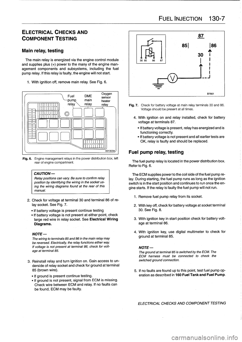
1
.
With
ignition
off,
remove
main
relay
.
See
Fig
.
6
.
.
iommooommmoi
~
"""
Fuel
DME
sensor
CA
UTION-
Relay
positions
can
vary
.
Be
sure
to
confirm
relay
position
by
identífyíng
the
wiring
in
the
socket
us-
ingthe
wiring
diagramsfound
at
the
rearof
this
manual
.
0013034)
Fuel
pump
relay,
testing
FUEL
INJECTION
130-
7
87
851186
30
~j
1
.
Remove
fuel
pump
relay
from
its
socket
.
87661
Fig
.
7
.
Check
for
battery
voltage
at
main
relay
terminals
30
and
86
.
Voltage
should
be
present
at
all
times
.
4
.
With
ignition
on
and
relay
installed,
check
for
battery
voltage
at
terminals
87
.
"
If
battery
voltage
is
present,relay
has
energized
and
is
functioningcorrectly
.
"
lf
battery
voltage
is
not
present
and
al¡
earlier
tests
are
OK,
relay
is
faulty
and
should
be
replaced
.
Fig
.
6
.
Engine
management
relays
in
the
power
distribution
box,
left
rear
of
engine
compartment
.
The
fuel
pump
relay
is
located
in
the
power
distribution
box
.
Refer
to
Fig
.
6
.
The
ECM
supplies
power
to
the
coil
side
of
the
fuel
pump
re-
lay
.
During
starting,
the
fuel
pump
runs
as
long
as
the
ignition
switch
isin
the
start
position
and
continues
to
run
once
theen-
gine
starts
.
If
the
relay
ís
faulty
the
fuel
pump
will
notrun
.
2
.
Check
for
voltage
at
terminal
30
and
terminal
86
of
re-
¡ay
socket
.
See
Fig
.
7
.
2
.
With
key
off,
check
for
batteryvoltage
at
socket
terminal
"
If
battery
voltage
is
present
continue
testing
30
.
See
Fig
.
8
.
"
lf
battery
voltage
is
not
present
at
either
point,
check
large
red
wire
in
relay
socket
.
See
Electrical
Wiring
3
.
With
ignition
key
in
start
position
check
for
battery
volt-
Diagrams
.
age
at
terminal
86
.
NOTE-
4
.
With
ignition
key,
use
digital
multimeter
to
check
for
The
wiring
to
terminals
85
and
86
in
the
main
relay
may
ground
at
terminal
85
.
be
reversed
.
Electrically,
the
relay
functions
either
way
.
lf
voltage
ís
not
present
at
terminal
86,
check
for
volt-
NOTE-
age
at
terminal
85
.
The
ground
atterminal
85
is
switched
by
the
ECM
.
The
ECM
hamess
must
be
connected
to
check
the
3
.
Reinstall
relay
and
turn
ignition
on
.
Gainaccess
to
un-
switched
ground
connection
.
derside
of
relay
socket
and
check
for
ground
at
terminal
85
(brown
wire)
.
5
.
If
no
faults
are
found
up
tothis
point,
testfuel
pump
op-
"
lf
ground
is
present
continue
testing
.
eration
as
described
in
160
Fuel
Tank
and
Fuel
Pump
.
"
If
ground
is
not
present,
signal
from
ECM
is
missing
.
Check
wire
between
ECM
and
relay
.
If
no
faults
can
be
found,
ECM
may
be
faulty
.
ELECTRICAL
CHECKS
AND
COMPONENT
TESTING
Page 154 of 759
130-
8
FUEL
INJECTION
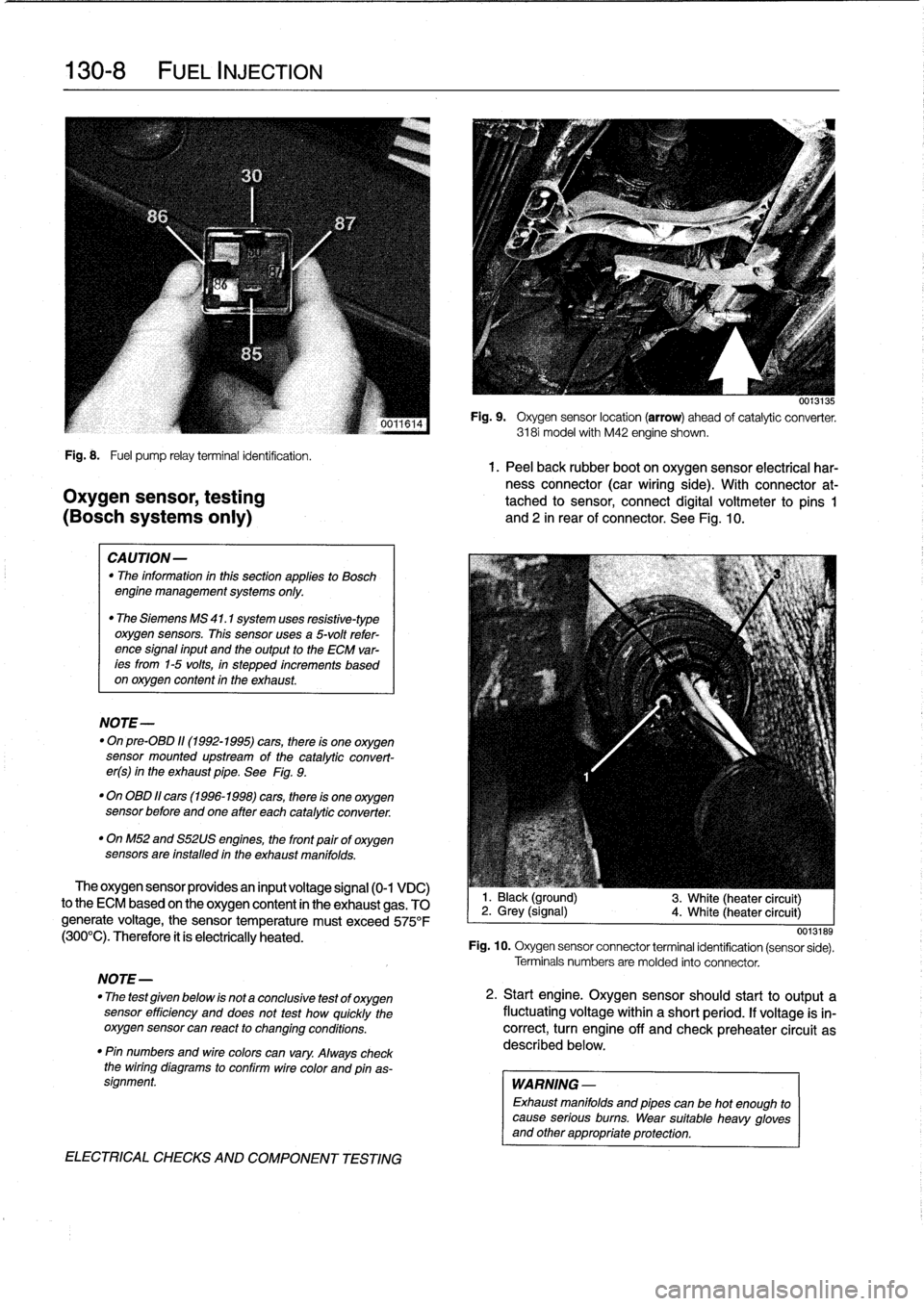
Fig
.
8
.
Fuel
pump
relayterminal
identification
.
1.
Peel
back
rubber
boot
on
oxygen
sensor
electrical
har-
ness
connector
(car
wiring
side)
.
With
connector
at-
Oxygen
sensor,
testing
tached
to
sensor,
connect
digital
voltmeter
to
pins
1
(BOSch
systems
only)
and
2
in
rear
of
connector
.
See
Fig
.
10
.
CAUTION-
"
The
information
inthis
sectionapplies
to
Bosch
engine
management
systems
only
.
"
The
Siemens
MS
41
.1
system
uses
resistive-type
oxygen
sensors
.
This
sensor
uses
a
5-volt
refer-
ence
signal
input
and
the
output
to
the
ECM
var-
ees
from
1-5
volts,
in
stepped
increments
based
on
oxygen
content
in
the
exhaust
.
NOTE-
"
On
pre-08D
11(1992-1995)
cars,
there
is
one
oxygen
sensor
mounted
upstream
of
the
catalytic
convert-
er(s)
in
the
exhaust
pipe
.
See
Fig
.
9
.
"
On
OBD
11
cars
(1996-1998)
cars,
there
is
one
oxygen
sensor
before
andone
after
each
catalytic
converter
.
"
OnM52
and
S52US
engines,
the
front
pairof
oxygen
sensors
are
installed
in
the
exhaust
manifolds
.
The
oxygen
sensor
providesan
input
voltage
signal
(0-1
VDC)
to
the
ECM
based
on
the
oxygen
content
in
the
exhaust
gas
.
TO
generate
voltage,
the
sensor
temperature
must
exceed
575°F
(300°C)
.
Therefore
it
ís
electrically
heated
.
NOTE-
"
The
test
given
below
is
not
a
conclusive
test
of
oxygen
sensor
efficiency
and
does
not
test
how
quickly
the
oxygensensor
can
react
to
changing
conditions
.
"
Pin
numbers
and
wirecolors
can
vary
.
Always
check
the
wiring
diagrams
to
conflrm
wire
color
and
pinas-
signment
.
ELECTRICAL
CHECKS
AND
COMPONENT
TESTING
0013135
Fig
.
9
.
Oxygen
sensor
location
(arrow)
ahead
of
catalytic
converter
.
3181
model
with
M42
engine
shown
.
1
.
Black
(ground)
2
.
Grey
(signal)
4
.
White
(heater
circuit)
3
.
White
(heater
circuit)
0013189
Fig
.
10
.
Oxygen
sensor
connector
terminal
identification
(sensor
sede)
.
Terminals
numbers
are
molded
into
connector
.
2
.
Start
engine
.
Oxygen
sensorshould
start
to
output
a
fluctuating
voltage
within
a
short
period
.
If
voltage
is
in-
correct,
turn
engine
off
and
check
preheater
circuit
as
described
below
.
WARNING
-
Exhaust
manifolds
and
pipes
can
be
hot
enough
to
cause
serious
burns
.
Wear
suitable
heavy
gloves
and
other
appropriate
protection
.