terminal 7 BMW 325i 1992 E36 Manual PDF
[x] Cancel search | Manufacturer: BMW, Model Year: 1992, Model line: 325i, Model: BMW 325i 1992 E36Pages: 759
Page 384 of 759
600-
4
ELECTRICAL
SYSTEM-GENERAL
Voltage
and
Voltage
Drops
The
wires,
connectors,
and
switches
that
carry
current
are
designed
with
very
low
resistance
so
that
current
flows
with
a
minimum
loss
of
voltage
.
A
voltage
drop
is
caused
by
higher
than
normal
resistance
in
a
circuit
.
This
additional
resistance
actually
decreases
or
stops
the
flow
of
current
.
A
voltage
drop
can
be
noticed
byproblems
ranging
fromdim
headlights
to
sluggish
wipers
.
Some
common
sources
of
voltage
drops
are
corroded
or
dirty
switches,
dirty
or
corroded
connections
or
contacts,
and
loose
or
corroded
ground
wires
and
ground
con-
nections
.
A
voltage
drop
test
is
a
good
test
to
make
if
current
is
flowing
through
the
circuit,
butthe
circuit
is
not
operating
correctly
.
A
voltage
drop
test
will
help
to
pinpoint
a
corroded
ground
strap
or
a
faulty
switch
.
Normally,
there
should
be
less
than
1
volt
drop
across
most
wires
or
closed
switches
.
A
voltage
drop
across
a
connector
or
short
cable
shouldnot
exceed
0
.5
volts
.
Voltage,
measuring
1
.
Connect
digital
multimeternegative
lead
to
a
reliable
ground
point
oncar
.
NOTE-
The
negative
(-)
battery
terminal
is
alwaysa
good
ground
point
.
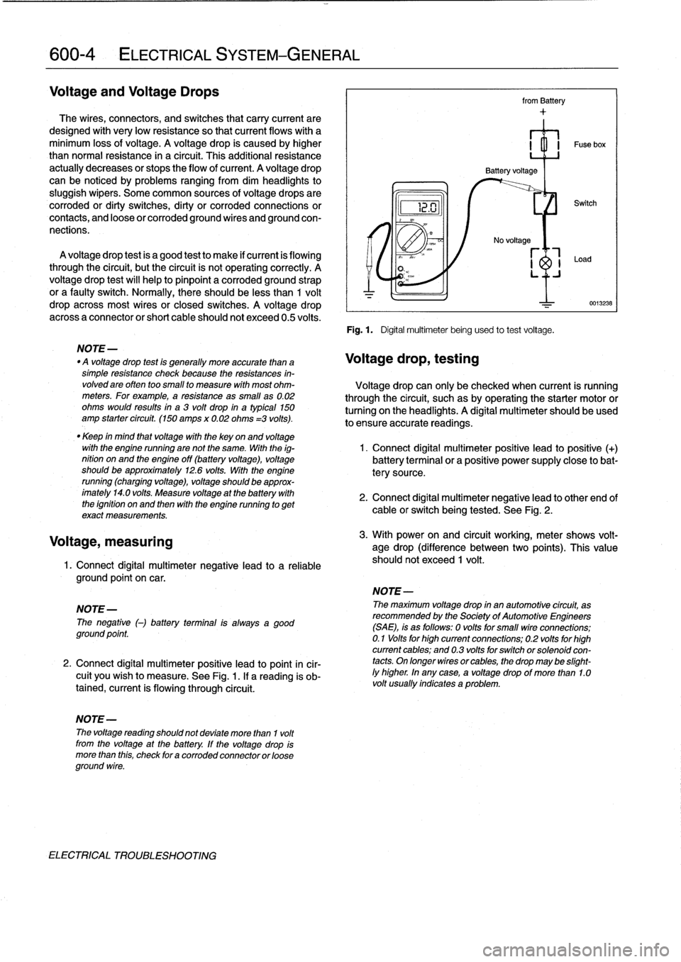
2
.
Connect
digital
multimeter
positive
lead
to
point
incir-
cuit
you
wish
to
measure
.
See
Fig
.
1
.
If
a
reading
is
ob-
tained,
current
is
flowing
through
circuit
.
NOTE-
The
voltage
reading
shouldnot
deviate
more
than
1
volt
from
the
voltage
at
the
battery
.
If
the
voltage
drop
is
more
than
this,
check
for
acorroded
connector
or
cose
ground
wire
.
ELECTRICAL
TROLIBLESHOOTING
from
Battery
Fig
.
1
.
Digital
multimeterbeing
used
to
test
voltage
.
No
voltage
r_l
-1
Load
LJ
Switch
NOTE-
The
maximum
voltage
drop
in
an
automotive
circuit,
as
recommended
by
the
Society
of
AutomotiveEngineers
(SAE),
is
as
follows
:
0
voltsfor
small
vire
connections
;
0
.1
Volts
for
high
current
connections
;
0
.2
volts
for
high
current
cables
;
and
0
.3volts
for
switch
or
solenoidcon-
tacts
.
On
longer
wires
or
cables,
the
drop
may
be
slight-ly
higher
.
In
any
case,
a
voltage
drop
of
more
than
1.0volt
usually
indicates
a
problem
.
0013238
NOTE-
"
A
voltage
drop
test
is
generally
more
accuratethan
a
Voltage
drop,
testing
simple
resistance
check
because
the
resistances
in-
volvedare
often
too
small
to
measure
with
most
ohm-
Voltage
drop
can
only
be
checked
when
current
is
running
meters
.
For
example,
a
resistance
as
small
as0
.02
through
the
circuit,
suchasby
operating
the
starter
motor
or
ohms
would
results
in
a
3
volt
drop
in
a
typical
150
turning
onthe
headlights
.
A
digital
multimeter
should
beused
amp
starter
circuit
.
(150
amps
x
0
.02
ohms
=3
volts)
.
lo
ensure
accurate
readings
.
"
Keep
in
mind
that
voltage
with
the
key
on
and
voltage
with
the
engine
running
arenotthe
same
.
With
the
ig-
1
.
Connect
digital
multimeter
positive
lead
to
positive
(+)
nition
on
and
the
engine
off
(battery
voltage),
voltage
battery
terminalor
a
positive
power
supply
close
lo
bat
should
be
approximately
12
.6volts
.
With
the
engine
tery
source
.
running
(charging
voltage),
voltage
should
be
approx-
imately
14
.0
volts
.
Measure
voltage
at
the
battery
with
2
.
Connect
digital
multimeter
negativelead
to
other
end
of
the
ignition
on
and
then
with
the
engine
running
to
get
cable
orswitch
being
tested
.
See
Fig
.
2
.
exact
measurements
.
3
.
With
power
on
and
circuit
working,
meter
shows
volt-
age
drop
(difference
between
two
points)
.
This
value
should
not
exceed
1
volt
.
Page 386 of 759
00-
6
ELECTRICAL
SYSTEM-GENERAL
Short
circuit,
testing
with
ohmmeter
Short
circuit,
testing
with
voltmeter
1
.
Remove
blown
fuse
from
circuit
and
disconnect
cables
1
.
Remove
blown
fusefrom
circuit
.
from
battery
.
2
.
Disconnect
harness
connector
from
circuifs
loador
2
.
Disconnect
harness
connector
from
circuit's
loador
consumer
.
consumer
.
3
.
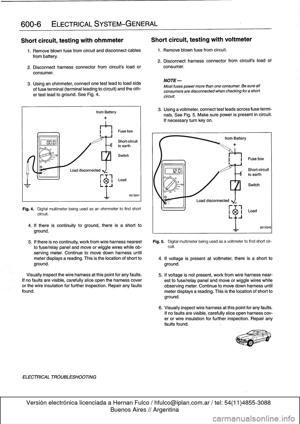
Using
an
ohmmeter,
connect
one
test
lead
to
loadside
of
f
use
terminal
(terminal
leading
to
circuit)
and
the
oth-
ertest
lead
to
ground
.
See
Fig
.
4
.
Load
disconnected
from
Battery
LO
n
I
~
Shotrouit
vu
.uto
earthth
Switch
Load
0013241
Fig
.
4
.
Digital
multimeter
being
usedasan
ohmmeter
to
find
short
circuit
.
4
.
lf
there
is
continuity
to
ground,
there
is
a
short
to
ground
.
ELECTRICAL
TROUBLESHOOTING
NOTE-
Most
fuses
power
more
than
one
consumer
.
Be
sure
aff
consumers
are
disconnected
when
checking
for
a
short
circuit
.
3
.
Using
a
voltmeter,
connect
test
leads
across
f
use
termi-
nals
.
See
Fig
.
5
.
Make
sure
power
is
present
ín
circuit
.
lf
necessary
turn
keyon
.
~2
.U
from
Battery
Load
disconnected
Short-circuit
to
earth
I
Fuse
box
0013240
5
.
If
there
is
no
continuity,
work
from
wire
harness
hearest
Fig
.
5
.
Digital
multimeter
being
usedas
a
voltmeter
to
find
short
cir
to
fuse/relay
panel
and
move
or
wiggle
wireswhile
ob-
cuit
.
serving
meter
.
Continue
to
movedown
harness
until
meter
displays
a
reading
.
This
is
the
location
of
short
to
4
.
lf
voltage
is
present
at
voltmeter,
there
is
a
short
to
ground
.
ground
.
Visually
inspect
the
wire
harness
at
this
point
for
any
faults
.
5
.
lf
voltage
is
not
present,
work
from
wire
harness
near-
If
no
faults
are
visible,
carefully
slice
open
the
harnesscover
est
to
fuse/relay
panel
and
move
orwiggle
wireswhile
or
the
wire
insulation
for
further
inspection
.
Repair
any
faults
observing
meter
.
Continue
to
move
down
harness
until
found
.
meter
displays
a
reading
.
This
is
the
location
of
short
to
ground
.
6
.
Visually
inspect
wire
harness
atthis
point
for
any
faults
.
lf
no
faults
are
visible,
carefully
slice
open
harness
cov-
erorwire
insulation
for
further
inspection
.
Repair
any
faults
found
.
Page 429 of 759
612
Switches
and
Electrical
Accessories
GENERAL
.
.
.
.
.
.
.
.
.
...
.
.
.
.
.
...
.
......
.612-1
Headlight
switch,
replacing
..
.
...
.
.
.
.
.
.
.
.
.
612-5
Foglight
switch,
replacing
....
.
.
.
.
.
.
.
.
.
.
.
.
.
612-5
INTERIOR
SWITCHES
.
.
...
.
.
.
.
.
.
.
.....
612-1
Hazard
warning
switch,
replacing
.
.
.
.
.
.
.
.
.
.612-5
Turn
signal
switch
and
wiper
switch,
Powerwindow
switch,
replacing
.
.
.
...
.
.
.
.
.
612-5
replacing
.
.
.
.
.
.
.
...
.
.
.
.....
.
....
.
.
.
.
612-1
Outside
mirrorswitch,
replacing
.
.
.
.
.....
.
.
.612-6
Ignition
Switch
Assembly
.
.
.
.
.
.
.
.
....
.
...
612-3
Ignition
electrical
switch,
replacing
.
...
.
....
612-3
INTERIOR
LIGHTS
.
.
................
.
..
612-6
Ignition
lock
cylinder,
replacing
.
.
.
.
.....
.
..
612-4
Dome
light,
rear
map
lights,
trunk
light,
Headlight
and
Foglight
Switch
Assembly
.
.
.
.
612-5
replacing
bulbs
.
......
.
.
.
.
.
.
.
.
.
.....
.
.612-7
GENERAL
Turn
signal
switch
and
wiper
switch,
replacing
Thissection
covers
replacement
of
interior
switches
and
accessories
.
The
procedures
for
removing
the
turn
signal
stalk
switch
and
the
wiper
system
stalk
switchare
similar
.
When
working
on
electrical
switches,
always
disconnect
the
negative
(-)
cable
from
the
battery
and
insulate
the
cable
end
to
prevent
accidental
re-connection
.
CAUTION-
Prior
to
disconnectiog
the
battery,
read
the
battery
disconnection
cautions
given
at
the
front
of
this
manual
on
page
viii
.
WARNING
-
The
cars
covered
by
this
manual
are
equipped
with
a
Supplemental
Restraint
System
(SRS)
that
auto-'
matically
deploys
one
or
more
airbags
.
Each
airbag
unit
houses
an
explosive
powerful
charge
.
Any
work
involving
the
SRS
system
should
only
be
per-
formed
byan
authorized
BMW
dealer
.
Making
re-
pairs
without
the
proper
knowledge
and
special
test
equipment
may
cause
serious
personal
injury
.
See
721
Airbag
System
(SRS)
3
.
With
front
wheels
pointed
straight
ahead,
remove
steer-
"
Testing
and
replacement
information
for
the
oil
ores-
¡ng
wheel
.
See
320
Steering
and
Wheel
Alignment
.
sure
switch
is
covered
in
119
Lubrication
System
.
NOTE-
"
Wirfng
diagramscan
be
found
in
Electrical
Wiring
Diagrams
.
"
Fuse,
relay
and
electrical
component
locations
can
be
found
in
610
Electrical
Component
Locations
.
"
Replacement
information
for
thetransmission
gear
position/neutral
safety
switch
is
covered
in
250
Gear-
shift
Unkage
.
INTERIOR
SWITCHES
NOTE
-
To
preventmarring
interior
trim,
wrap
the
tips
of
screw-
drivers
and
pliers
with
tape
beforeprying
out
switches
or
electrical
accessories
.
SWITCHES
AND
ELECTRICAL
ACCESSORIES
612-1
1
.
Disconnect
negative
(-)
cable
from
battery
and
cover
terminal
with
insulating
material
.
2
.
Remove
airbag
unit
from
steering
wheel
.
See
721
Air-
bag
System
(SRS)
.
Store
airbag
unit
in
a
safe
placew¡th
pad
facing
up
.
NOTE
-
To
helo
with
reassembly,
mark
steering
wheel
and
col-
umn
before
disassembly
.
4
.
Remove
trim
panel
from
lower
left
side
of
instrument
panel
.
See513
Interior
Trim
.
INTERIOR
SWITCHES
Page 431 of 759
Ignition
Switch
ASsembly
3
.
Remove
screw
retaining
lower
steering
column
cover
and
remove
cover
.
Refer
to
Fig
.
1
.
,
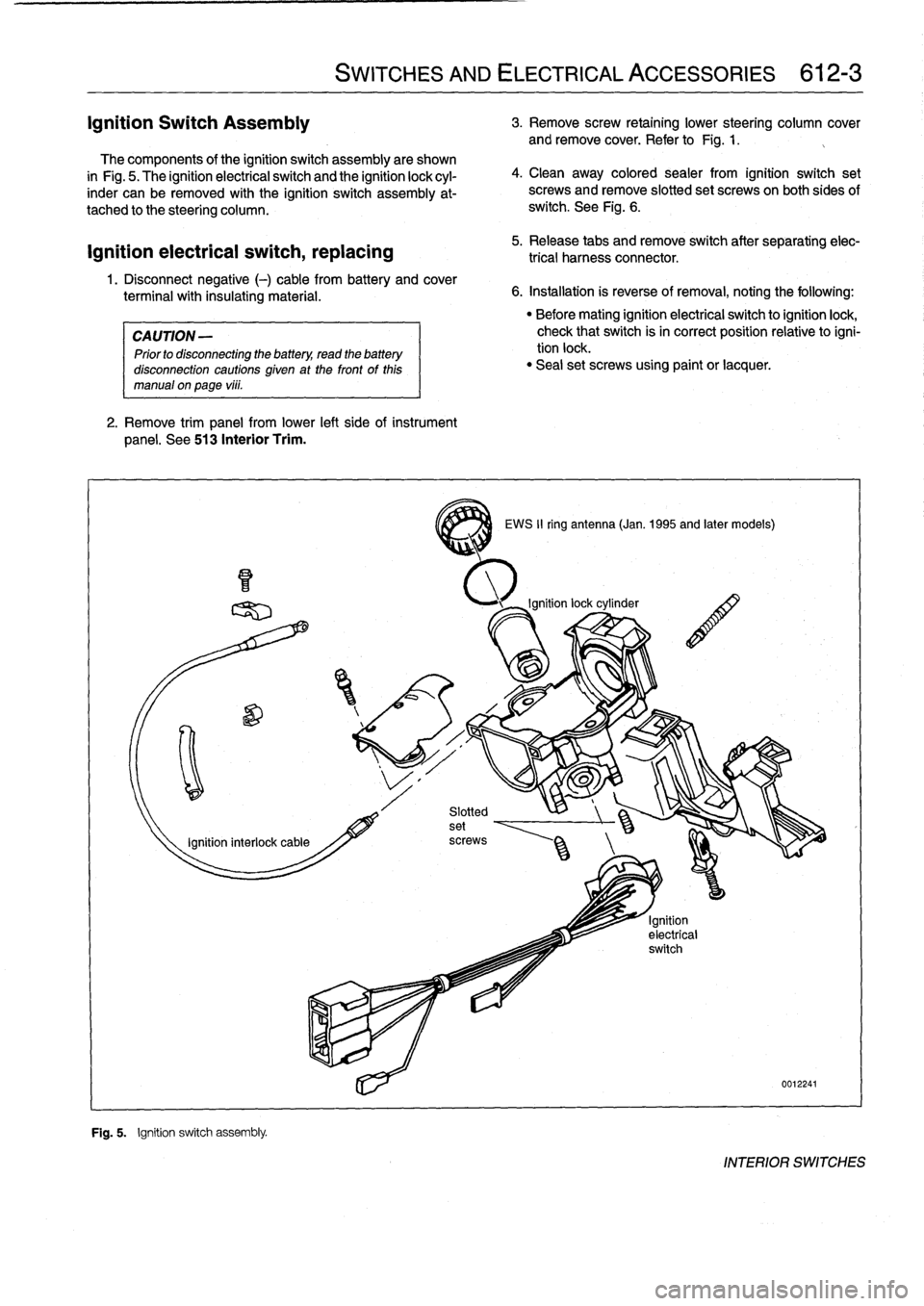
The
components
of
the
ignition
switch
assembly
are
shown
in
Fig
.
5
.
The
ignitionelectrical
switch
and
the
ignition
lock
cyl-
inder
can
be
removed
with
the
ignition
switch
assembly
at-
tached
to
the
steering
column
.
ignition
electrical
switch,
replacing
1
.
Disconnect
negative
(-)
cable
from
battery
and
cover
terminal
with
insulating
material
.
CAUTION
-
Prior
to
disconnecting
the
battery,
read
the
battery
disconnection
cautions
given
at
the
front
of
this
manual
on
page
vi¡¡
.
2
.
Remove
trim
panel
from
lower
left
side
of
instrument
panel
.
See
513
Interior
Trim
.
F~
"
Fig
.
5
.
Ignition
switch
assembly
.
SWITCHES
AND
ELECTRICAL
ACCESSORIES
612-3
4
.
Clean
away
colored
sealer
from
ignition
switch
set
screws
and
remove
slotted
set
screwson
both
sides
of
switch
.
See
Fig
.
6
.
5
.
Release
tabs
andremove
switch
after
separating
elec-
trical
harness
connector
.
6
.
Installation
is
reverse
of
removal,
noting
the
following
:
3
EWS
II
ring
antenna
(Jan
.
1995
and
later
models)
"
Before
mating
ignition
electrical
switch
toignitionlock,
check
that
switch
isin
correct
position
relativetoigni-
tion
lock
.
"
Seal
set
screws
using
paint
or
lacquer
.
0012241
INTERIOR
SWITCHES
Page 437 of 759
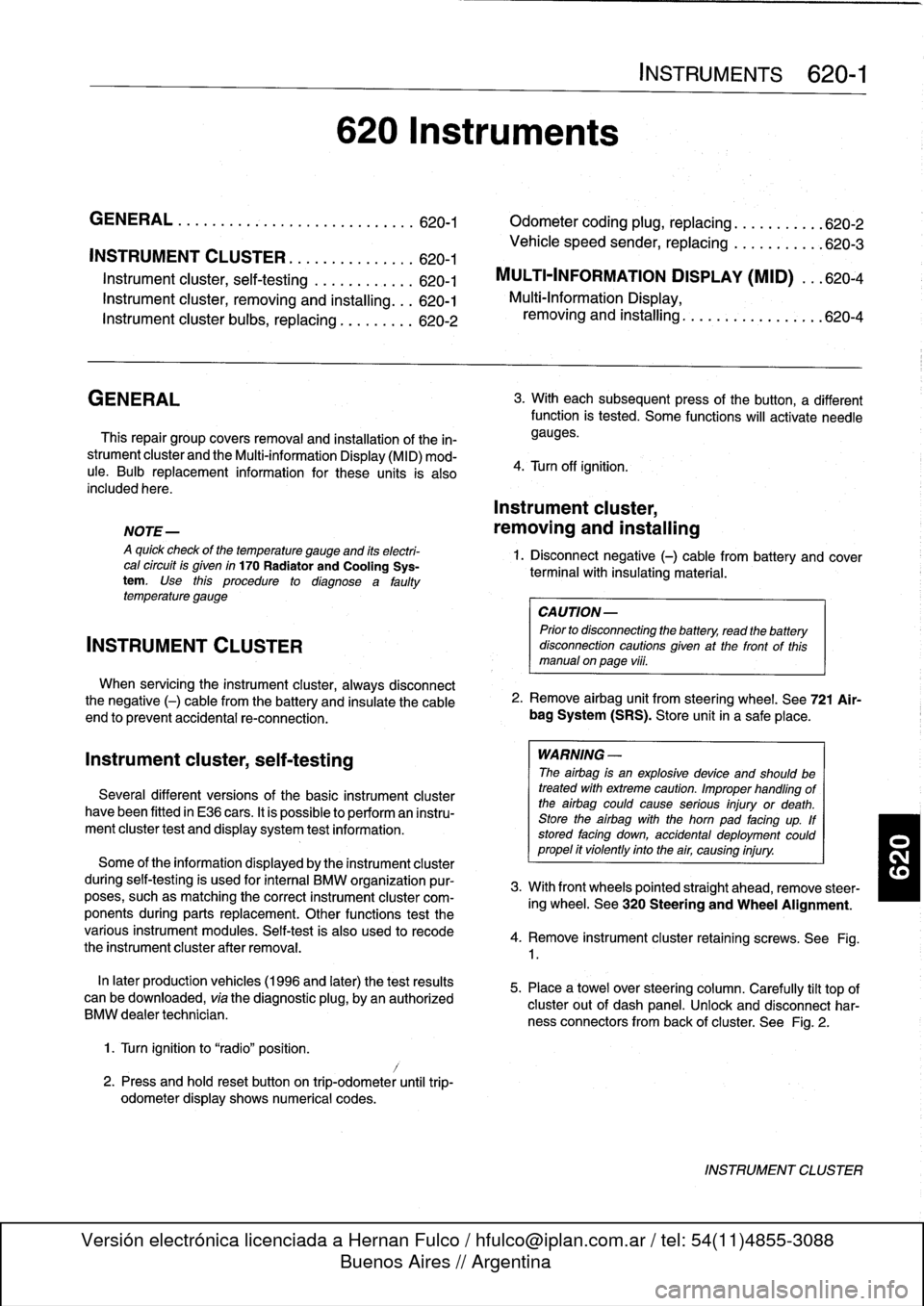
INSTRUMENT
CLUSTER
....
.
.
.
.
.
...
.
..
620-1
Instrument
cluster,
seif-testing
.
.
.......
.
..
620-1
Instrument
cluster,
removing
and
installing
...
620-1
Instrument
cluster
bulbs,
replacing
.
.
.
.
.
.
...
620-2
GENERAL
This
repair
group
covers
removal
and
installation
of
the
in-
strument
cluster
and
the
Multi-information
Display
(MID)
mod-
ule
.
Bulb
replacement
information
for
these
units
is
also
included
here
.
NOTE
-
A
quick
check
of
the
temperature
gauge
and
its
electri-
cal
circuitis
given
in
170
Radiator
and
Cooling
Sys-
tem
.
Use
this
procedure
to
diagnosea
faulty
temperature
gauge
INSTRUMENT
CLUSTER
When
servicing
the
instrument
cluster,
always
disconnect
the
negative
(-)
cable
from
the
battery
and
insulate
the
cable
end
to
prevent
accidental
re-connection
.
Instrument
cluster,
seif-testing
Severa¡
different
versions
of
the
basic
instrument
cluster
havebeen
fitted
in
E36
cars
.
It
is
possibleto
perform
an
instru-
ment
cluster
test
and
display
system
test
information
.
Some
of
the
information
displayed
by
the
instrument
cluster
during
seif-testing
is
used
for
interna¡
BMW
organizationpur-
poses,
suchasmatching
the
correct
instrument
cluster
com-
ponents
during
parts
replacement
.
Other
functions
test
the
various
instrument
modules
.
Self-test
is
also
used
to
recode
the
instrument
cluster
after
removal
.
In
later
production
vehicles
(1996
and
later)
the
test
results
canbe
downioaded,
via
the
diagnostic
plug,
byan
authorized
BMW
dealertechnician
.
1
.
Turn
ignition
to
"radio"position
.
2
.
Press
and
hold
reset
button
on
trip-odometer
untiltrip-
odometer
display
shows
numerical
codes
.
620
Instruments
4
.
Turn
off
ignition
.
Instrument
cluster,
removing
and
installing
INSTRUMENTS
620-1
GENERAL
.....
.
.
.
.
.
.
.
.
.
.........
.
....
620-1
Odometer
coding
plug,
replacing
.....
.
.
.
.
.
.
620-2
Vehicle
speed
sender,
replacing
...
.
.
.
.
.
.
.
.
620-3
MULTI-INFORMATION
DISPLAY
(MID)
.
.
.
620-4
Multi-Information
Display,
removing
and
installing
..
.
....
.
.........
620-4
3
.
With
each
subsequent
press
of
the
button,
a
different
function
is
tested
.
Some
functions
will
activate
need1e
gauges
.
1
.
Disconnect
negative
(-)
cable
from
battery
and
cover
terminal
with
insulating
material
.
CAUTION-
Prior
to
disconnectiog
the
battery,
read
the
battery
disconnection
cautionsgiven
at
the
front
of
this
manual
on
page
vi¡¡
.
2
.
Remove
airbag
unit
from
steering
wheel
.
See
721
Air-
bag
System
(SRS)
.
Store
unit
in
a
safe
place
.
WARNING
-
The
airbag
is
an
explosive
devfce
and
should
be
treated
with
extreme
caution
.
Improper
handling
of
the
airbag
could
cause
serious
injury
or
death
.
Store
the
airbag
with
the
horn
pad
facing
up
.
If
stored
facing
down,
accidental
deployment
couldpropel
it
vfolently
into
the
air,
causing
injury
.
3
.
With
front
wheels
pointed
straight
ahead,
remove
steer-
ing
wheel
.
See
320
Steering
and
Wheel
Alignment
.
4
.
Remove
instrument
cluster
retaining
screws
.
See
Fig
.
1
.
5
.
Place
a
towel
over
steering
column
.
Carefully
tilt
top
of
cluster
out
of
dash
panel
.
Unlock
and
disconnect
har-
ness
connectors
from
back
of
cluster
.
See
Fig
.
2
.
INSTRUMENT
CLUSTER
Page 465 of 759
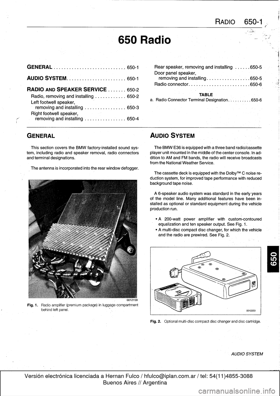
GENERAL
.........
.
.......
.
.
.
.
.
.
.
.
.
..
650-1
Rear
speaker,
removing
and
installing
.
.
.
.
.
.650-5
Door
panel
speaker,
AUDIO
SYSTEM
............
.
.
.
.
.
.
.
.
.
..
650-1
removing
and
installing
.
.
.
.
.....
.
.
.
.
.
.
.
.650-5
Radio
connector
..
.
.
.
.
.
.
.
.
.
.......
.
.
.
.
.
.
650-6
RADIO
AND
SPEAKER
SERVICE
.
.
.
.
.
..
650-2
Radio,
removingand
installing
.
.
.
.
.
.
...
.
..
650-2
Left
footwell
speaker,
removing
and
installing
.
....
.
.
.
.....
.
.
.
650-3
Right
footwell
speaker,
removing
and
installing
.
....
.
.
.
.....
.
..
650-4
GENERAL
AUDIO
SYSTEM
Thissection
coversthe
BMW
factory-installed
sound
sys-
The
BMW
E36
is
equipped
with
a
three
band
radio/cassette
tem,
including
radio
and
speaker
removal,
radio
connectors
player
unit
mounted
in
the
middle
of
thecenter
console
.
In
ad
and
terminal
designations
.
dítion
to
AM
and
FM
bands,
the
radio
will
receive
broadcasts
from
theNational
Weather
Service
.
The
antenna
is
incorporated
into
the
rear
window
defogger
.
650
Radio
Fig
.
1
.
Radio
amplifier
(premiumpackage)
in
luggage
compartment
behind
left
panel
.
RADIO
650-1
TABLE
a
.
Radio
Connector
Terminal
Designation
...
.
......
650-6
The
cassette
deck
is
equipped
with
the
Do1byTM
C
noise
re-
ductionsystem,
for
improved
tape
performance
with
reduced
background
tape
noise
.
A
6-speaker
audio
system
was
standard
in
the
early
years
ofthe
model
line
.
Many
additional
features
have
been
in-
stalled
as
optional
or
standard
equipment
duringthevehicle
production
run
.
"
A
200-watt
power
amplifier
with
custom-contoured
equalization
and
ten
speaker
output
.
See
Fig
.
1
.
"
A
multi-disc
compact
disc
changer,
for
which
the
vehicle
and
the
radio
are
prewired
.
See
Fig
.
2
.
Fig
.
2
.
Optional
multi-disc
compact
disc
changerand
disc
cartridge
.
AUDIO
SYSTEM
Page 469 of 759
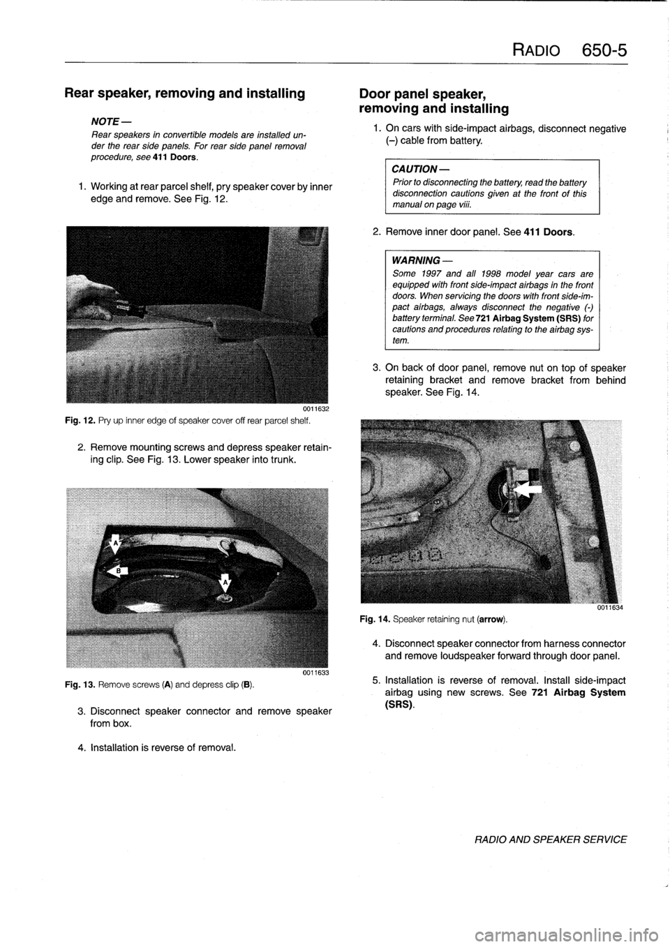
Rear
speaker,
removing
and
installing
Door
panel
speaker,
removing
and
installing
NOTE
-
Rear
speakers
in
convertible
models
are
installed
un-
der
the
rear
side
panels
.
For
rearside
panelremoval
procedure,
see
411Doors
.
1
.
Working
at
rear
parcel
shelf,
pry
speakercoverby
inner
edge
and
remove
.
See
Fig
.
12
.
0011632
Fig
.
12
.
Pry
up
inner
edge
of
speaker
cover
off
rear
parcel
shelf
.
2
.
Remove
mountingscrews
and
depress
speaker
retain-
ing
clip
.
See
Fig
.
13
.
Lower
speaker
into
trunk
.
Fig
.
13
.
Remove
screws
(A)
and
depress
clip
(B)
.
4
.
Installation
is
reverse
of
removal
.
0011633
3
.
Disconnect
speaker
connector
andremove
speaker
from
box
.
RAM
650-5
1.
On
carswith
side-impact
airbags,
disconnect
negative
(-)
cable
from
battery
.
CAUTION-
Prior
to
disconnecttog
the
battery,
read
the
battery
disconnection
cautions
given
at
the
front
of
this
manual
on
page
vi¡¡
.
2
.
Remove
inner
door
panel
.
See
411
Doors
.
WARNING
-
Some
1997
and
all
1998
model
year
cars
are
equipped
with
front
side-impact
airbags
in
the
front
doors
.
When
servicing
the
doors
with
front
side-im-
pact
airbags,
alwaysdisconnect
the
negative
()
battery
terminal
.
See
721Airbag
System
(SRS)
for
cautions
and
procedures
relating
to
theairbag
sys-
tem
.
3
.
On
back
of
door
panel,
remove
nut
on
top
of
speaker
retaining
bracket
and
remove
bracket
from
behind
speaker
.
See
Fig
.
14
.
Fig
.
14
.
Speaker
retaining
nut
(arrow)
.
4
.
Disconnect
speaker
connector
from
harness
connector
and
remove
loudspeaker
forwardthrough
door
panel
.
5
.
Installation
is
reverse
of
removal
.
Install
side-impact
airbag
using
new
screws
.
See
721
Airbag
System
(SRS)
.
RADIO
AND
SPEAKER
SERVICE
Page 470 of 759
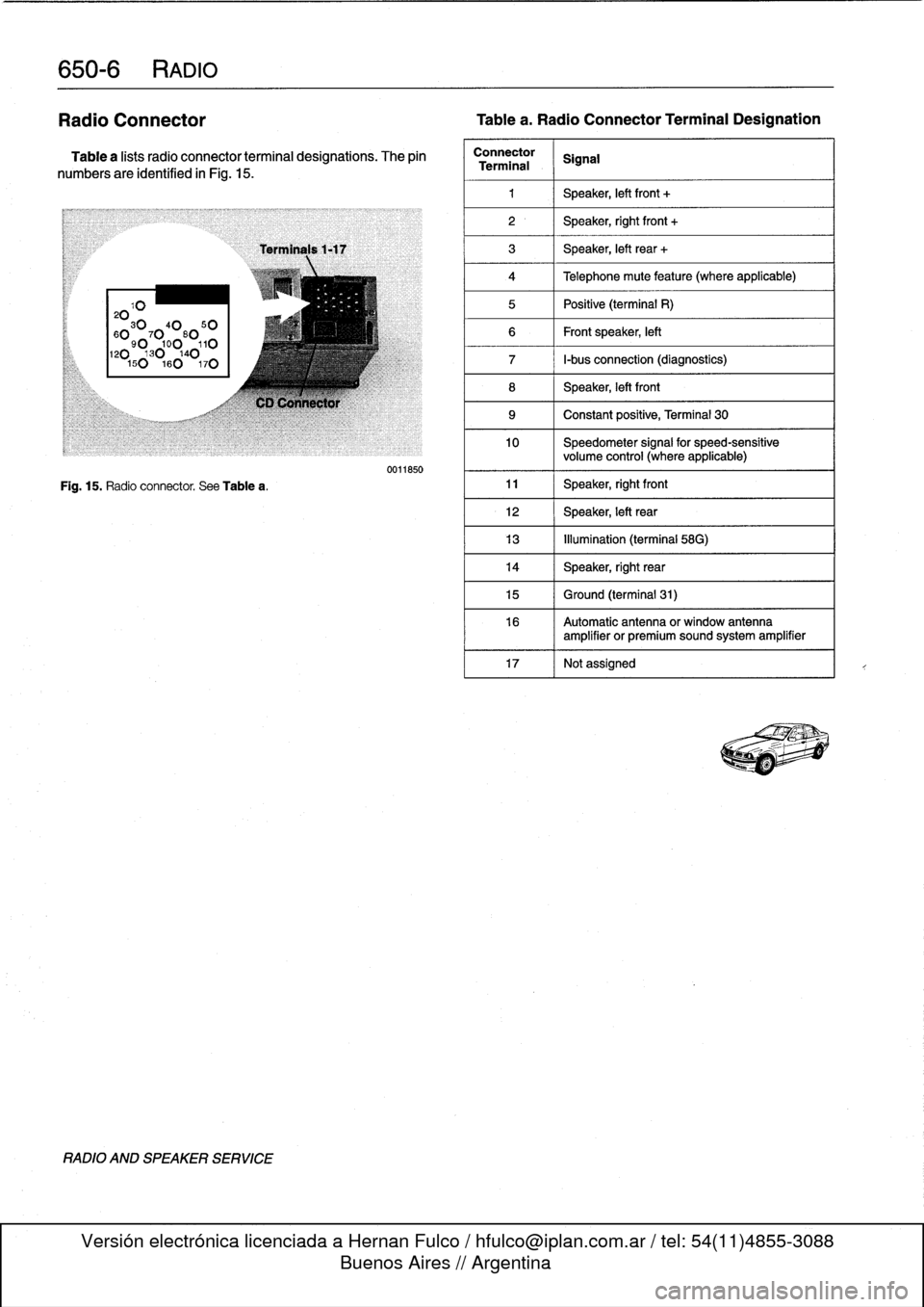
650-
6
RADIO
Radio
Connector
Tablea
.
Radio
Connector
Terminal
Designation
Table
a
lists
radio
connector
terminal
designations
.
The
pin
numbers
are
identified
in
Fig
.
15
.
20103040
50
60
90
7
0
0
80
110120130140150160
170
Fig
.
15
.
Radio
connector
.
See
Tablea
.
RADIO
AND
SPEAKER
SERVICE
Terminals
1-17
C1)
Connector
0011850
Connector
SignalTerminal
1
1
Speaker,
left
front
+
2
1
Speaker,
right
front
+
3
1
Speaker,
left
rear
+
4
1
Telephone
mute
feature
(where
applicable)
5
1
Positive
(terminal
R)
6
1
Frontspeaker,
left
7
1
I-bus
connection
(diagnostics)
8
Speaker,
left
front
9
1
Constant
positive,
Terminal
30
10
Speedometer
signal
for
speed-sensitive
volume
control
(where
applicable)
11
1
Speaker,
rightfront
12
1
Speaker,
left
rear
13
1
Illumination
(terminal
58G)
14
Speaker,
right
rear
15
1
Ground
(terminal
31)
16
Automatic
antenna
or
window
antenna
amplifier
or
premiumsound
system
amplifier
17
Notassigned
!'~_T-
Page 477 of 759
721
Airbag
System
(SRS)
Airbag
Systems
.......
.
...
.
.
.
.
.
....
.
.
.
.
721-1
AIRBAG
SENSORS
AND
ELECTRONICS
721-2
SRS
Warning
Light
and
Fault
Display
.
.
.
.
.
..
721-2
Airbagcontact
ring,
replacing
........
.
.
.
.
.
721-3
Airbag
crash
sensor,replacing
..
.
....
.
...
.
721-4
ZAE
control
module,
replacing
.
.
.
.........
721-5
GENERAL
This
repair
group
covers
only
removal
and
installation
of
air-
bag
components
.
Airbag
system
repair
and
fault
diagnosis
is
not
covered
here
.
Diagnostics,
component
testing,
and
airbag
system
repair
should
be
carried
out
by
trained
BMW
service
technicians
.
NOTE-
Special
test
equipment
is
required
to
retrieve
SRS
fault
codes,
diagnose
system
faults,
and
resetltum
off
the
SRS
indicator
light
.
The
SRS
indicator
light
will
remain
on
until
any
problem
has
been
corrected
and
the
fault
memory
has
been
cleared
.
When
servicing
cars
equipped
with
SRS,
the
precautions
on
this
page
mustbeobserved
to
prevent
personal
injury
.
Airbag
Systems
The
airbag
system
installed
on
E36
cars
through
the
1993
model
year
consisted
of
a
single
airbag
in
the
steering
wheel
.
This
systemcan
be
identified
by
the
orange
crash
sensors
lo-
cated
on
the
front
wheel
wells
and
the
absence
of
a
passenger
side
airbag
.
The
ZAE
airbag
system,
starting
in
model
year
1994
(pro-
duction
date9/93
and
later),
provides
both
a
driver
side
and
a
passenger
sideairbag
.
On
ZAE
vehicles,
the
crash
sensorsare
integrated
into
the
airbag
control
module,
located
under
thecenter
of
the
rear
seat
.
The
ZAE
control
module
triggers
deployment
of
the
airbags
When
it
sensos
the
vehicle
deceler-
ating
at
a
rate
equivalent
to
a
head-on
collisionof
at
least
13
mph
(18
km/h)
.
In
some
1997
4-door
models
and
all
1998
models,
side-impact
airbags
were
installed
in
the
front
doors
.
The
airbag
units
are
mounted
behindthe
door
trim
panels
.
Caution
mustbeused
when
working
on
vehicle
systems
in
the
proximity
of
air
bags,
such
as
the
steering
column,
the
dashboard,
or
the
doors
.
AIRBAG
SYSTEM
(SRS)
721-1
GENERAL
.
.
.
.
.
.
.
.
.
.
.......
.
......
.
.
.
.
721-1
Front
side-impact
airbag
crash
sensor,
removing
and
installing
....
.
.....
.
.....
.
721-5
AIRBAGS
..............
.
.
.
.
.
.
.
.
.
.
.
.
.
.
.
721-5
Driver
side
airbag,
removing
and
installing
.
.
.
721-5
Passenger
side
airbag,
removing
and
installing
..............
.
.
.721-6
Front
side-impact
airbag,
removing
and
installing
.
.
.
.
.
.
.
.
.
.
......
.721-7
WARNING
-
"
Airbag(s)
are
inflated
byan
explosive
device
.
Handled
improperly
or
without
adequate
safe-
guards,
the
System
can
be
very
dangerous
.
Spe-
cial
precautions
must
be
observed
prior
to
any
work
ator
near
the
driverside
airbag,
the
passen-
ger
side
airbag
(where
applicable)
or
the
side-im-
pact
airbags
(where
applicable)
.
"
The
airbag
is
a
vehicle
safety
system
.
Serious
in-
jury
may
result
if
System
service
is
attempted
by
persons
unfamiliar
with
the
BMW
SRS
and
its
ap-
proved
service
procedures
.
BMW
advises
that
all
inspection
and
service
be
performed
by
an
autho-
rized
BMW
dealer
.
"
Always
disconnect
the
battery
and
cover
the
neg-
ative
()
battery
terminal
with
an
insulator
before
startingdiagnostic,
troubleshooting
or
service
worknot
associated
with
SRS,
and
before
doing
any
welding
on
the
car
.
"
If
an
airbag
has
been
activated
due
to
an
acci-dent,
BMW
specifies
that
SRS
components
be
replaced
.
For
more
information
on
post-collision
SRS
service,
see
an
authorized
BMW
dealer
.
"
Do
not
allow
the
airbag
unit
to
come
in
contact
with
cleaning
solutions
orgrease
.
Never
subject
an
airbag
unit
to
temperatures
aboye
212°F
(100°C)
.
When
reconnecting
the
battery,
no
per-
son
should
be
inside
the
vehicle
.
"
Always
place
an
airbag
unitthat
has
been
re-
moved
from
its
packaging
with
the
padded
sidefacing
upward
.
Do
not
leave
an
airbag
unlt
unat-
tended
.
"
!f
the
airbag
unit
or
airbag
control
modulehas
been
dropped
froma
height
of
!
1
2
meter
(1
Y2
ft.)
ormore,
theairbag
unit
should
not
be
installed
.
Aírbag
system
components
are
shown
in
Fig
.
1.
GENERAL
Page 479 of 759
1
.
Disconnect
negative
(-)
cable
from
battery
and
cover
negative
terminal
with
insulating
material
.
CA
UTION-
Prior
to
disconnectiog
the
battery,
read
the
battery
disconnection
cautions
given
at
the
front
of
this
manual
on
page
viii
.
2
.
Remove
driver
sideairbag
from
steering
wheel
.
See
Driver
side
airbag,
removing
and
installing
in
this
repair
group
.
3
.
With
wheels
facing
straight
ahead
and
steering
wheel
centered,
remove
steering
wheel
.
See320
Steering
and
Wheel
Alignment
.
4
.
Remove
contact
ring
cover
(flat
plastic
ring
containing
warning
text)
from
steering
wheel,
íf
applicable
.
5
.
Disconnect
ground
wire,
if
applicable
6
.
Lift
out
plastic
lock
from
steering
wheel,
if
applicable
.
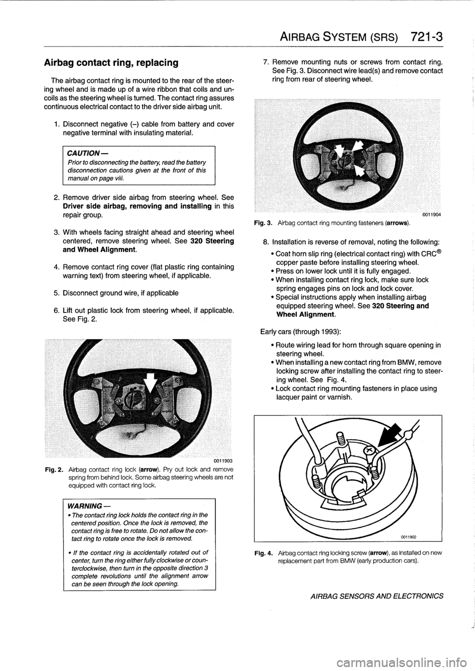
See
Fig
.
2
.
0011903
Fig
.
2
.
Airbag
contact
ring
lock(arrow)
.
Pry
out
lock
and
remove
spríng
from
behind
lock
.
Some
airbag
steering
wheels
are
not
equipped
with
contact
ring
lock
.
WARNING
-
"
The
contact
ring
lock
holds
the
contact
ring
in
the
centered
position
.
Once
the
lock
is
removed,
the
contact
ring
is
free
to
rotate
.
Do
not
allow
the
con-
tact
ring
to
rotate
once
the
lock
is
removed
.
"
If
the
contact
ring
is
accidentally
rotated
outof
center,
turn
the
ring
either
fully
clockwise
orcoun-
terclockwise,
then
turn
in
the
opposite
direction
3
complete
revolutions
until
the
alignment
arrow
canbe
seen
through
the
lock
opening
.
AIRBAG
SYSTEM
(SRS)
721-
3
Airbagcontact
ring,
replacing
7
.
Remove
mounting
nutsor
screws
from
contact
ring
.
See
Fig
.
3
.
Disconnect
wire
lead(s)
andremove
contact
The
airbag
contact
ring
is
mounted
to
the
rear
of
the
steer-
ring
from
rear
of
steering
wheel
.
ing
wheel
and
is
made
up
of
a
wireribbon
that
cofs
and
un-
coils
as
the
steering
wheel
is
tumed
.
The
contact
ring
assures
continuous
electrical
contact
to
the
driver
side
airbag
unit
.
Fig
.
3
.
Airbag
contact
ring
mounting
fasteners(arrows)
.
8
.
Installation
is
reverse
ofremoval,noting
the
following
:
"
Coat
horn
slip
ring
(electrical
contact
ring)
with
CRC
®
copper
paste
before
installing
steering
wheel
.
"
Press
on
lower
lock
until
it
ís
fully
engaged
.
"
When
installing
contact
ringlock,
make
sure
lock
spring
engages
pins
on
lock
and
lock
cover
.
"
Special
instructions
apply
when
installing
airbag
equipped
steering
wheel
.
See320
Steering
and
Wheel
Alignment
.
Early
cars
(through
1993)
:
"
Route
wiring
lead
for
horn
through
squareopening
in
steering
wheel
.
"
When
installing
a
new
contact
ring
from
BMW,
remove
locking
screw
after
installing
the
contact
ringto
steer-
ing
wheel
.
See
Fig
.
4
.
"
Lock
contact
ring
mounting
fasteners
in
place
using
lacquer
paint
or
varnish
.
0011904
Fig
.
4
.
Airbag
contact
ring
locking
screw
(arrow),
as
installed
on
new
replacement
part
from
BMW
(early
production
cars)
.
AIRBAG
SENSORS
AND
ELECTRONICS