650 BMW 325i 1992 E36 Workshop Manual
[x] Cancel search | Manufacturer: BMW, Model Year: 1992, Model line: 325i, Model: BMW 325i 1992 E36Pages: 759
Page 3 of 759
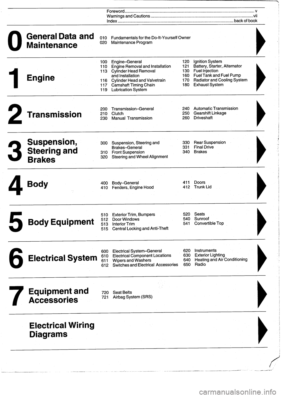
General
Data
and
010
FundamentalsfortheDo-lt-YourselfOwner
Maintenance
020
Maintenance
Program
Engine
Transmission
Suspension,
Steering
and
Brakes
4
Body
100
Engine-General
110
Engine
Removal
and
Installation
113
Cylinder
Head
Removal
and
Installation
116
Cylinder
Head
and
Valvetrain
117
Camshaft
Timing
Chain
119
Lubrication
System
200
Transmission-General
210
Clutch
230
Manual
Transmission
510
Exterior
Trim,
Bumpers
520
Seats
Bo
y
Equipment
512
DoorWTdws
540
nr
t
513
InteriorTrim
541
Convertible
Top
515
Central
Locking
and
Anti-Theft
600
Electrical
System-General
620
Instruments
Electrical
S
stem
610
Electrical
Component
Locations
630
Exterior
Lighting
611
Wipers
and
Washers
640
Heating
and
Air
Conditioning
6
612
Switches
and
Electrical
Accessories
650
Radio
Equipment
and
720
SeatBelts
Accessories
721
Airbag
System
(SRS)
Electrical
Wiring
Diagrams
Foreword
.
...
.
.
.
..................
.
.
.
.....
.
............
.
...
.
.
.
.
.
................
.
.
.
.....
.
......
.
................
.
.
.
.....
v
Warnings
and
Cautions
.....
.
...
.
.
.
.
.
..........
.
...
.
.
.
.
.
......
.
.........
.
.
.
...
.
.
.
......
.
.
.
.
.
............
.
.
.
.
.
.
.vii
Index
..............
.
.
.
.....
.
............
.
...
.
.
.
.
.
........
.
...
.
.
.
.
.
.......
.
......
.
...
.
.
.
.
.
.
.
........
.
.
.
..
back
of
book
300
Suspension,
Steering
and
330
RearSuspension
Brakes-General
331
Final
Drive
310
Front
Suspension
340
Brakes
320
Steering
and
Wheel
Alignment
400
Body-General
411
Doors
410
Fenders,
Engine
Hood
412
Trunk
Lid
120
Ignition
System
121
Battery,Starter,
Alternator
130
Fue¡
Injection
160
Fuel
Tank
and
Fuel
Pump
170
Radiator
and
Cooling
System180
Exhaust
System
240
Automatic
Transmission
250
Gearshift
Linkage
260
Driveshaft
Page 130 of 759
120-
6
IGNITION
SYSTEM
Crankshaft
position/rpm
sensor,
testing
and
replacing
(front
mounted)
1
.
Disconnect
sensor
harness
connector
.
2
.
Using
a
digital
multimeter,
check
resistance
between
terminals
1
and
2
in
connector
.
See
Fig
.
10
.
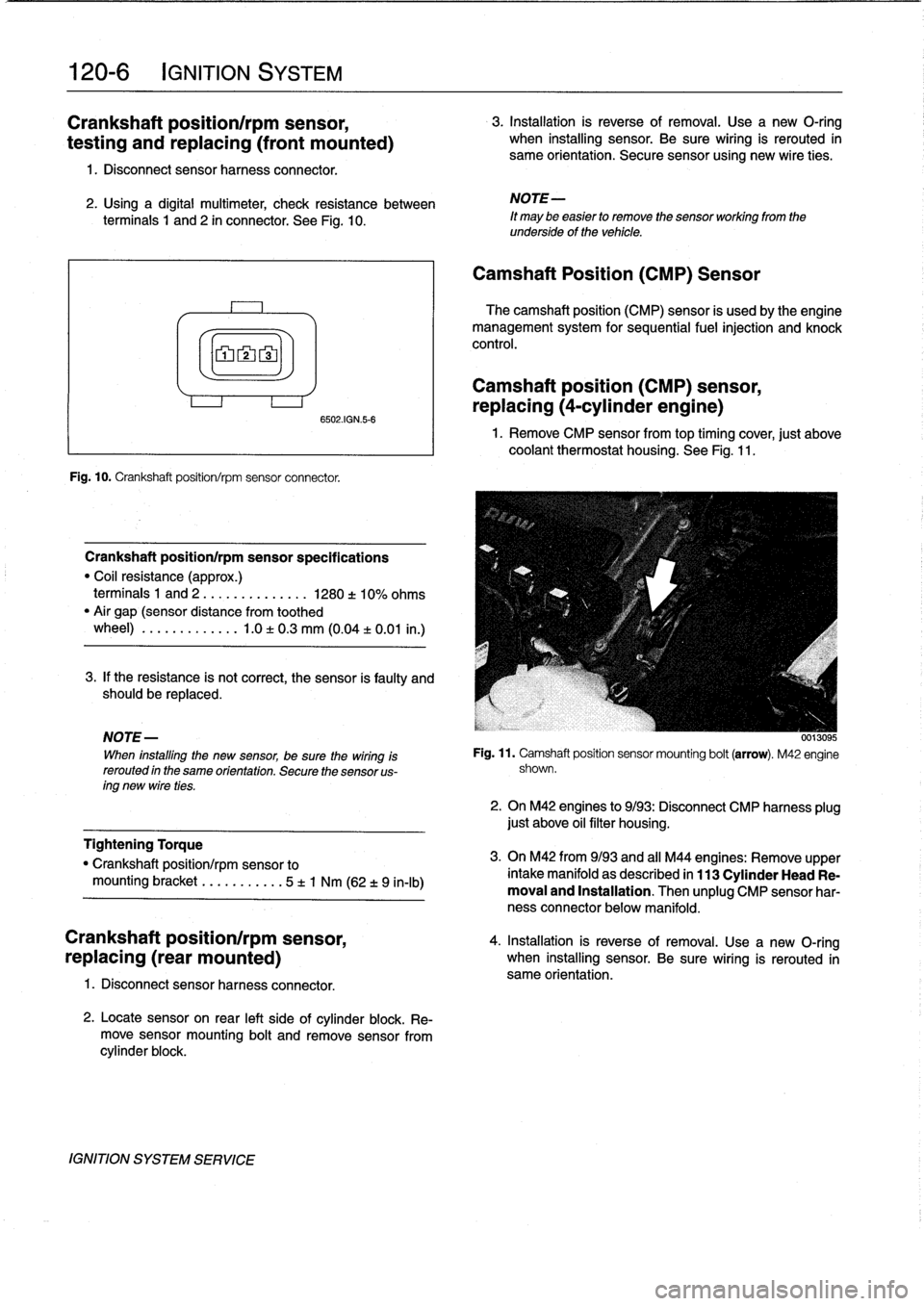
n1
n2n3
Fig
.
10
.
Crankshaft
position/rpm
sensorconnector
.
Crankshaft
positionlrpm
sensor
specifications
"
Coil
resistance
(approx
.)
terminais
1
and
2
....
.
..
...
....
1280
±
10%
ohms
"
Air
gap
(sensor
distance
from
toothed
wheel)
..
.
.
........
.1
.0
±
0
.3
mm
(0
.04
±
0
.01
in
.)
3
.
If
the
resistance
is
not
correct,
the
sensor
is
faulty
and
should
be
replaced
.
NOTE
-
When
installing
the
new
sensor,
be
sure
thewiring
Is
rerouted
in
the
same
orientation
.
Secure
the
sensor
us-
ing
new
wire
ties
.
Tightening
Torque
"
Crankshaft
position/rpm
sensor
to
mounting
bracket
.........
.
.
5
t
1
Nm
(62
t
9
in-lb)
Crankshaft
position/rpm
sensor,
4
.
Installation
is
reverse
of
removal
.
Use
a
new
O-ring
replacing
(rear
mounted)
when
installing
sensor
.
Be
sure
wiring
is
rerouted
in
same
orientation
.
1
.
Disconnect
sensor
harness
connector
.
6502AGN56
2
.
Locatesensor
on
rear
left
sideof
cylinder
block
.
Re-
move
sensormounting
bolt
and
remove
sensorfrom
cylinder
block
.
IGNITION
SYSTEM
SERVICE
3
.
Installation
is
reverse
of
removal
.
Use
a
new
O-ring
when
installing
sensor
.
Be
sure
wiring
is
rerouted
in
same
orientation
.
Secure
sensor
using
new
wire
ties
.
NOTE-
It
may
be
easier
to
remove
the
sensor
working
from
the
underside
of
the
vehicle
.
Camshaft
Position
(CMP)
Sensor
The
camshaft
position
(CMP)
sensor
is
usedby
the
engine
management
system
for
sequential
fuel
injection
and
knock
control
.
Camshaft
position
(CMP)
sensor,
replacing
(4-cylinder
engine)
1
.
Remove
CMP
sensorfromtop
timing
cover,
just
above
coolantthermostat
housing
.
See
Fig
.
11
.
Fig
.
11
.
Camshaft
position
sensor
mounting
bolt
(arrow)
.
M42
engine
shown
.
2
.
On
M42
engines
to
9/93
:
Disconnect
CMP
harness
plug
just
above
oil
filter
housing
.
3
.
On
M42
from9/93
and
all
M44
engines
:
Remove
upper
intake
manifold
as
described
in
113
Cylinder
Head
Re-
moval
and
Installation
.
Then
unplug
CMP
sensor
har-
ness
connector
below
manifold
.
Page 275 of 759
Rear
shock
absorber,
removing
and
installing
1.
Raisecar
and
remove
rear
wheels
.
WARNING
-
Make
sure
that
thecar
is
firmly
supportedon
jack
stands
designed
for
the
purpose
.
Place
the
jack
stands
beneatha
structural
chassis
point
.
Do
not
place
jack
stands
undersuspension
parts
.
2
.
Remove
rear
speakers
.
See
650
Radio
.
3
.
Pryoutluggage
compartment
liner
retaining
clips
and
peel
back
liner
to
gain
access
to
upper
shock
absorber
mounting
nuts
.
See
Fig
.
3
.
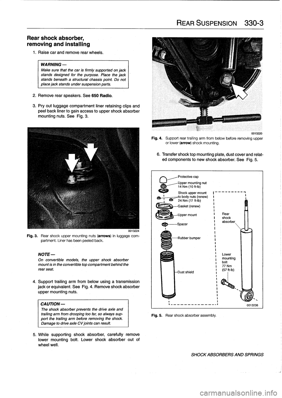
Fig
.
3
.
Rear
shock
upper
mounting
nuts
(arrows)
in
luggage
com-
partment
.
Liner
hasbeen
peeled
back
.
NOTE-
On
convertible
models,
the
uppershock
absorber
mount
is
in
the
convertible
top
compartment
behind
the
rear
seat
.
4
.
Support
trailing
arm
from
below
using
a
transmission
jack
orequivalent
.
See
Fig
.
4
.
Remove
shock
absorber
uppermounting
nuts
.
CAUTION-
The
shock
absorber
prevenís
the
drive
axle
and
trailing
arm
from
drooping
too
far,
so
always
sup-port
the
trailing
arm
before
removing
the
shock
.
Damage
to
drive
axle
CV
joints
can
result
.
0013224
5
.
While
supporting
shock
absorber,
carefully
remove
lower
mounting
bolt
.
Lower
shock
absorber
out
of
wheel
well
.
Fig
.
4
.
Support
rear
trailing
arm
from
below
before
removing
upper
or
lower
(arrow)
shock
mounting
.
6
.
Transfer
shocktopmounting
plate,
dust
coverand
relat-
ed
components
to
new
shock
absorber
.
See
Fig
.
5
.
'
Protective
cap
Upper
mounting
nut
14
Nm
(10
ft-Ib)
1120
Shock
upper
mount
,~,--~to
body
nuts
(renew)
I
-
'
~
24
Nm
(17
ft-Ib)
I
1
-Gasket
(renew)
I
1
pper
mount
I
Rear
I
shock
I
absorber
I
I
---spacer
REAR
SUSPENSION
330-
3
Rubber
bumper
Dust
shield
Fig
.
5
.
Rear
shock
absorber
assembly
.
Lower
mounting
bolt
77
Nm
I
(57
ft-Ib)
i
I
I
1
I
0013220
0013236
SHOCKABSORBERS
AND
SPRINGS
Page 315 of 759
GENERAL
This
repair
group
covers
front
and
rear
door
repair
informa-
tion,
including
removal
and
installationof
the
interior
doorpan-
els
.
DOORS
WARNING
-
Late
M3
moddis
havealuminum
doors
.
Use
extra
care
in
handling
aluminum
parts
in
order
to
avoid
damage
from
gouging
or
corrosión
.
NOTE-
"
For
information
on
the
power
door
windows
and
door
glass
replacement,
sea512Door
Windows
.
"
Forinformation
on
the
power
door
locking
system,
see
515
Central
Locking
and
Anti-Theft
.
WARNING
-
Some
1997
and
all
1998
cars
are
fitted
with
side-im-
pact
airbags
in
the
front
doors
.
When
servicing
doors
on
cars
with
front
side-impact
airbags,
always
dis-
connect
the
negative
(-)
battery
terminal
.
See
721
Airbag
System
(SRS)
for
cautions
and
procedures
relating
to
the
airbag
system
.
Front
orrear
door,
removing
and
installing
1
.
If
workingon
front
door
with
side-impact
airbag,
discon-
nect
negative
(-)
battery
cable
.
CAUTION
-
Prior
to
disconnectiog
the
battery,
read
the
battery
disconnection
cautions
given
at
the
front
of
this
manual
on
page
vüi
.
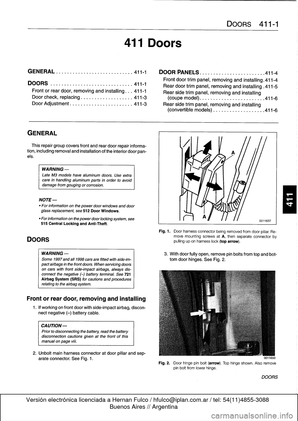
2
.
Unbolt
main
harness
connector
at
door
pillar
and
sep-
arate
connector
.
See
Fig
.
1
.
411
Doors
GENERAL
.............
.
.
.
.
.
.
.
.
.
.
.
.
.
..
411-1
DOOR
PANELS
.
.
.
.
.
.
.
...
.
.
.
.
.
.
.
.
.
...
.
.
411-4
Front
door
trim
panel,
removing
and
installing
.411-4
DOORS
..
.
.
.
.
.
.
.
.
.
...
.
.......
.
....
.
.
.
411-1
Rear
door
trim
panel,
removing
and
installing
.411-5
Front
or
reardoor,
removing
and
installing
..
.
411-1
Rear
side
trim
panel,
removing
and
installing
Door
check,
replacing
.
.
.
.
.
.
.
.
.
.
.
.
.......
411-3
(coupemodel)
.
.
.
.
.
.
....
.
.............
411-6
Door
Adjustment
.......
.
.
.
.
.
.
.
.
.
.
.
.....
411-3
Rear
side
trim
panel,
removing
and
installing
(convertible
models)
.
...
.
.
.
.
.
.
.
.
.
.
.
...
.
411-6
DOORS
411-1
Fig
.
1
.
Door
harness
connector
being
removed
fromdoor
pillar
.
Re-
move
mountingscrews
atA,
then
separate
connector
by
pulling
upon
harness
lock(top
arrow)
.
3
.
Withdoor
fully
open,
remove
pin
bolts
from
top
and
bot-
tom
door
hinges
.
See
Fig
.
2
.
0011650
Fig
.
2
.
Door
hinge
pin
bolt
(arrow)
.
Top
hinge
shown
.
Also
remove
pin
bolt
from
lowerhinge
.
DOORS
Page 347 of 759
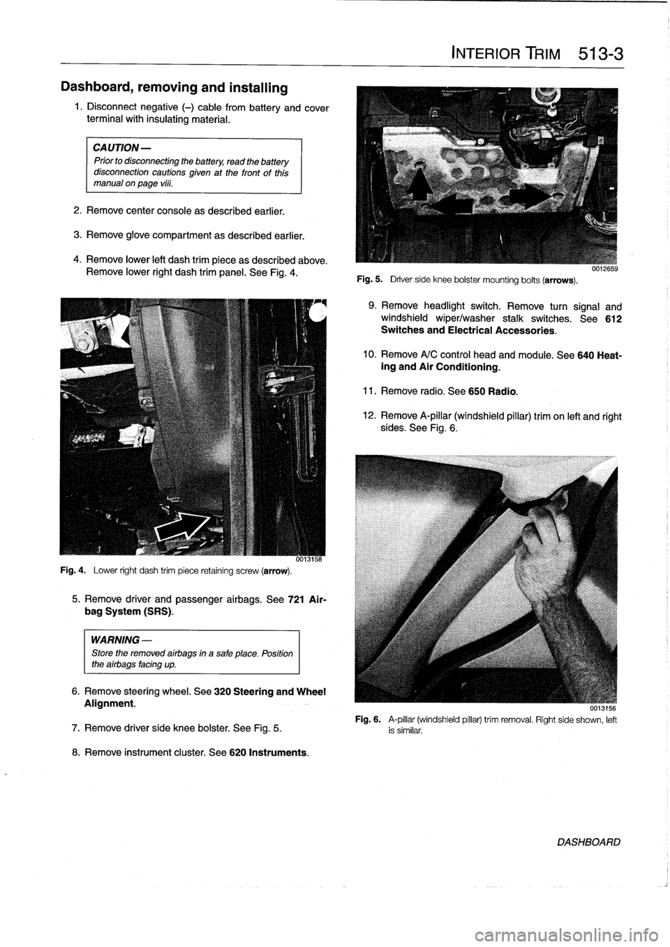
Dashboard,
removing
and
installing
1
.
Disconnect
negative
(-)
cable
from
battery
and
cover
terminal
with
insulating
material
.
CAUTION-
Prior
to
disconnectiog
the
battery,
read
the
battery
disconnection
cautionsgiven
at
the
front
of
this
manual
onpage
vi¡¡
.
2
.
Remove
center
console
as
described
earlier
.
3
.
Remove
glove
compartment
as
described
earlier
.
4
.
Remove
lower
left
dash
trim
piece
as
described
above
.
Remove
lower
right
dash
trim
panel
.
See
Fig
.
4
.
Fig
.
4
.
Lower
right
dash
trim
piece
retaining
screw
(arrow)
.
WARNING
-
Store
the
removed
airbags
in
a
safe
place
.
Position
the
airbags
facing
up
.
8
.
Remove
instrument
cluster
.
See
620
Instruments
.
5
.
Remove
driver
and
passenger
airbags
.
See
721
Air-
bag
System
(SRS)
.
6
.
Remove
steering
wheel
.
See
320
Steering
and
Wheel
Alignment
.
INTERIOR
TRIM
513-
3
Fig
.
5
.
Driver
side
knee
bolster
mounting
bolts
(arrows)
.
9
.
Remove
headlight
switch
.
Remove
turn
signal
and
windshield
wiper/washer
stalk
switches
.
See612
Switches
and
Electrical
Accessories
.
10
.
Remove
A/C
control
head
and
module
.
See
640
Heat-ing
and
Air
Conditioning
.
11
.
Remove
radio
.
See650
Radio
.
12
.
Remove
A-pillar
(windshield
pillar)
trim
on
left
and
right
sides
.
See
Fig
.
6
.
UU13156
Fig
.
6
.
A-pillar
(windshield
pillar)
trim
removal
.
Right
side
shown,
left
7
.
Remove
driver
side
knee
bolster
.
See
Fig
.
5
.
is
similar
.
DASHBOARD
Page 454 of 759
640-8
HEATING
AND
AIR
CONDITIONING
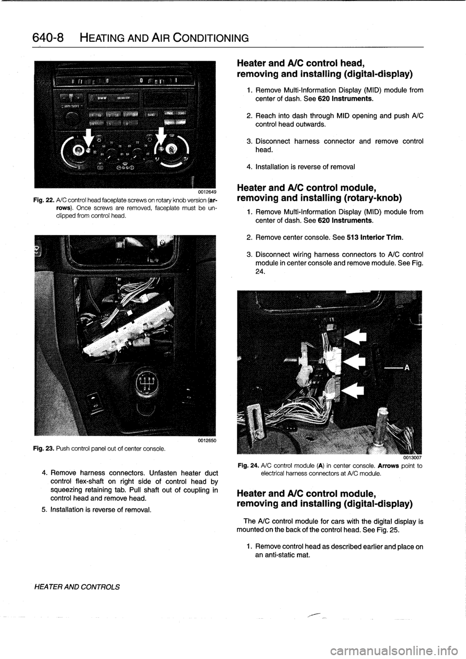
0012649
Fig
.
22
.
A/
C
control
head
faceplate
screwson
rotary
knob
version
(ar-
rows)
.
Once
screws
are
removed,
faceplate
must
be
un-
clipped
from
control
head
.
Fig
.
23
.
Push
control
panel
out
ofcenter
console
.
4
.
Remove
harness
connectors
.
Unfasten
heater
duct
control
flex-shaft
on
right
side
of
control
head
by
squeezing
retaining
tab
.
PA
shaftout
of
coupling
in
control
head
and
remove
head
.
5
.
Installation
is
reverseof
removal
.
HEATER
AND
CONTROLS
0012650
Heater
and
A/C
control
head,
removing
and
installing(digital-display)
1
.
Remove
Multi-Information
Display
(MID)
module
from
center
of
dash
.
See
620
Instruments
.
2
.
Reach
into
dash
through
MID
opening
and
push
A/C
control
head
outwards
.
3
.
Disconnect
harness
connector
and
remove
control
head
.
4
.
Installation
is
reverse
of
removal
Heater
andA/C
control
module,
removing
and
installing
(rotary-knob)
1
.
Remove
Multi-Information
Display
(MID)
module
from
center
of
dash
.
See
620
Instruments
.
2
.
Remove
center
console
.
See
513
Interior
Trim
.
3
.
Disconnect
wiring
harness
connectors
to
A/C
control
module
in
center
console
and
removemodule
.
See
Fig
.
24
.
0013007
Fig
.
24
.
A/
C
control
module
(A)
in
center
console
.
Arrows
point
to
electrical
harness
connectors
at
A/Cmodule
.
Heater
and
A/C
control
module,
removing
and
installing(digital-display)
TheA/C
control
module
for
cars
with
the
digital
display
is
mounted
on
the
back
of
the
control
head
.
See
Fig
.
25
.
1
.
Remove
control
head
as
described
earlier
and
place
onan
anti-static
mat
.
Page 465 of 759
GENERAL
.........
.
.......
.
.
.
.
.
.
.
.
.
..
650-1
Rear
speaker,
removing
and
installing
.
.
.
.
.
.650-5
Door
panel
speaker,
AUDIO
SYSTEM
............
.
.
.
.
.
.
.
.
.
..
650-1
removing
and
installing
.
.
.
.
.....
.
.
.
.
.
.
.
.650-5
Radio
connector
..
.
.
.
.
.
.
.
.
.
.......
.
.
.
.
.
.
650-6
RADIO
AND
SPEAKER
SERVICE
.
.
.
.
.
..
650-2
Radio,
removingand
installing
.
.
.
.
.
.
...
.
..
650-2
Left
footwell
speaker,
removing
and
installing
.
....
.
.
.
.....
.
.
.
650-3
Right
footwell
speaker,
removing
and
installing
.
....
.
.
.
.....
.
..
650-4
GENERAL
AUDIO
SYSTEM
Thissection
coversthe
BMW
factory-installed
sound
sys-
The
BMW
E36
is
equipped
with
a
three
band
radio/cassette
tem,
including
radio
and
speaker
removal,
radio
connectors
player
unit
mounted
in
the
middle
of
thecenter
console
.
In
ad
and
terminal
designations
.
dítion
to
AM
and
FM
bands,
the
radio
will
receive
broadcasts
from
theNational
Weather
Service
.
The
antenna
is
incorporated
into
the
rear
window
defogger
.
650
Radio
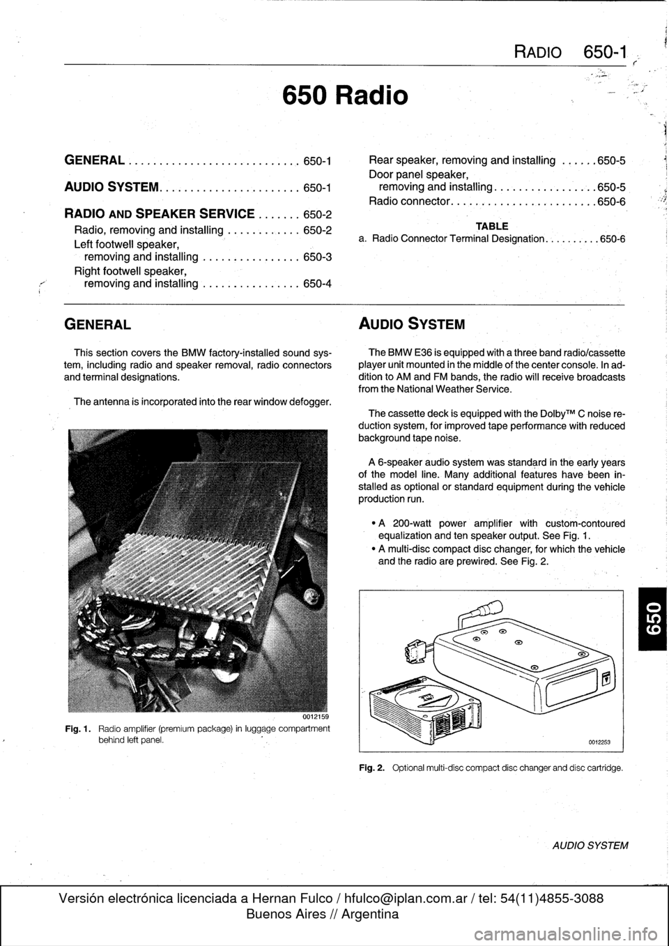
Fig
.
1
.
Radio
amplifier
(premiumpackage)
in
luggage
compartment
behind
left
panel
.
RADIO
650-1
TABLE
a
.
Radio
Connector
Terminal
Designation
...
.
......
650-6
The
cassette
deck
is
equipped
with
the
Do1byTM
C
noise
re-
ductionsystem,
for
improved
tape
performance
with
reduced
background
tape
noise
.
A
6-speaker
audio
system
was
standard
in
the
early
years
ofthe
model
line
.
Many
additional
features
have
been
in-
stalled
as
optional
or
standard
equipment
duringthevehicle
production
run
.
"
A
200-watt
power
amplifier
with
custom-contoured
equalization
and
ten
speaker
output
.
See
Fig
.
1
.
"
A
multi-disc
compact
disc
changer,
for
which
the
vehicle
and
the
radio
are
prewired
.
See
Fig
.
2
.
Fig
.
2
.
Optional
multi-disc
compact
disc
changerand
disc
cartridge
.
AUDIO
SYSTEM
Page 466 of 759
650-2
RADIO
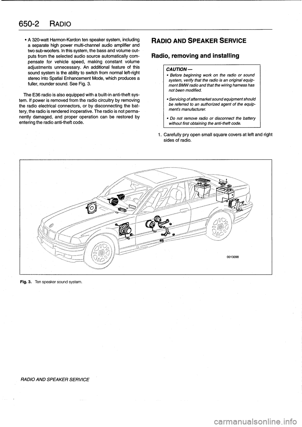
"
A
320-watt
Harmon-Kardon
ten
speaker
system,
including
RADIO
AND
SPEAKER
SERVICE
a
separate
high
power
multi-channel
audio
amplifier
and
two
sub-woofers
.
In
this
system,
thebass
and
volume
out-
puts
from
the
selected
audiosource
automatically
com-
Radio,
removing
and
installing
pensate
for
vehicle
speed,
making
constant
volume
adjustments
unnecessary
.
An
additional
feature
ofthis
CAUTION-
sound
system
is
the
ability
to
switch
from
normal
left-right
"
Before
beginning
work
on
the
radio
or
sound
stereo
into
Spatial
Enhancement
Mode,
which
produces
a
system,
verify
that
the
radio
is
an
original
equip-
fuller,
rounder
sound
.
See
Fig
.
3
.
ment
BMW
radio
and
that
thewiring
harness
has
not
been
modified
.
TheE36
radio
is
also
equipped
with
a
built-in
anti-theft
sys-
tem
.
lf
power
is
removed
from
the
radio
circuitry
by
removing
the
radio
electrical
connectors,
or
by
disconnecting
the
bat-
tery,
the
radio
is
rendered
inoperative
.
The
radio
is
not
perma-
nently
damaged,
and
proper
operation
can
be
restored
by
entering
the
radio
anti-theft
code
.
Fig
.
3
.
Ten
speaker
sound
system
.
RADIO
AND
SPEAKER
SERVICE
"
Servicing
of
aftermarket
sound
equipment
should
be
referredto
an
authorized
agent
of
the
equip-
ment's
manufacturer
.
"
Do
not
remove
radio
or
disconnect
the
batterywithout
first
obtaining
the
anti-theft
code
.
1.
Carefully
pry
open
small
square
covers
at
left
and
right
sides
of
radio
.
Page 467 of 759
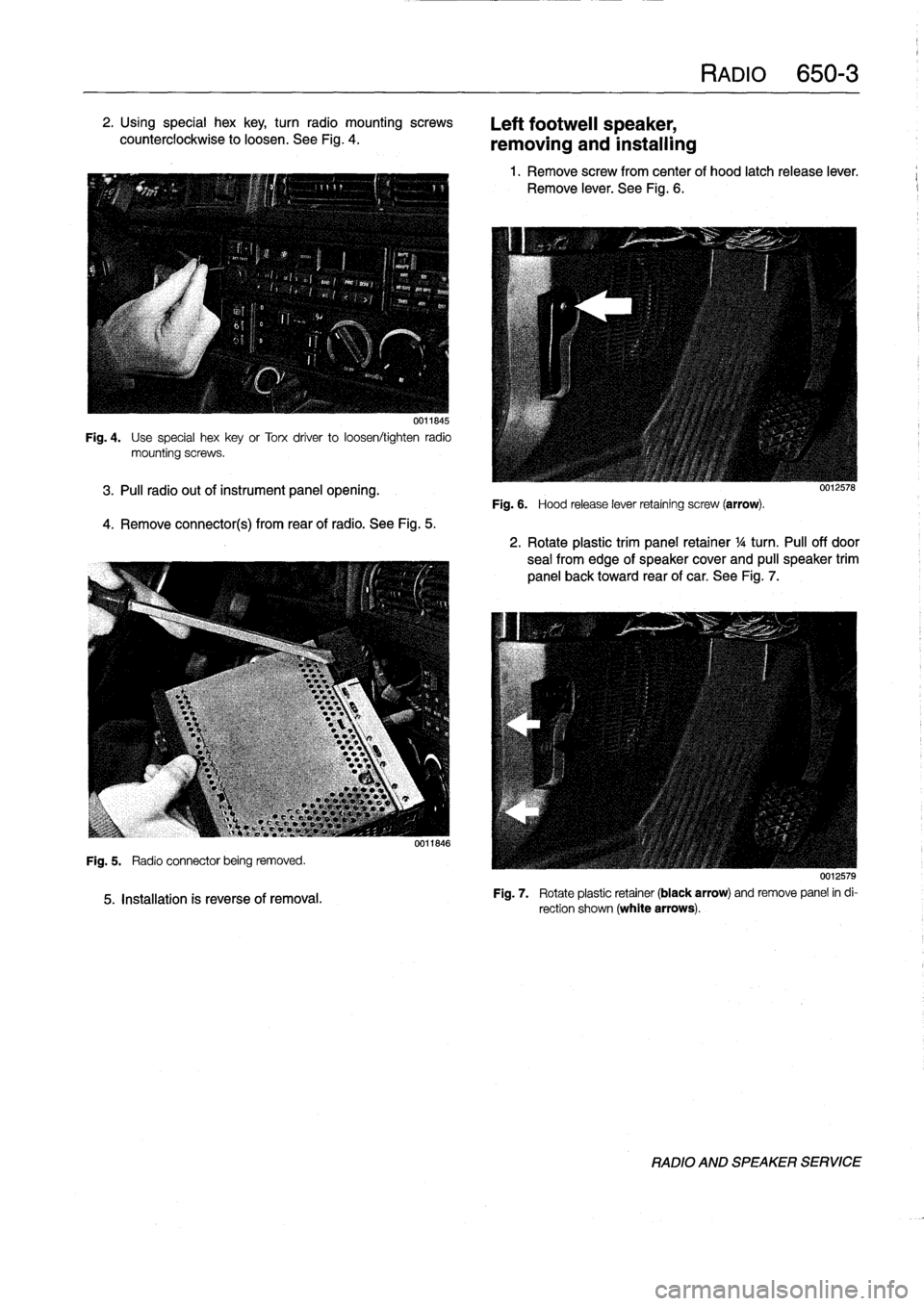
2
.
Using
special
hex
key,
turn
radio
mountingscrews
counterclockwise
to
loosen
.
See
Fig
.
4
.
0011845
Fig
.
4
.
Use
special
hexkey
or
Torx
driver
to
loosen/tighten
radio
mountingscrews
.
3
.
Pul¡
radio
out
of
instrument
panel
opening
.
4
.
Remove
connector(s)
from
rearof
radio
.
See
Fig
.
5
.
Fig
.
5
.
Radio
connector
being
removed
.
5
.
Installation
is
reverse
of
removal
.
0011846
Left
footweil
speaker,
removing
and
installing
Fig
.
6
.
Hood
release
lever
retaining
screw
(arrow)
.
RADIO
650-
3
1
.
Remove
screw
from
center
of
hood
latch
release
lever
.
Remove
lever
.
See
Fig
.
6
.
0012578
2
.
Rotate
plastic
trim
panel
retainer
1
/4
turn
.
Pul¡
off
door
sea¡
from
edge
of
speaker
cover
and
pull
speaker
trim
panel
back
toward
rear
of
car
.
See
Fig
.
7
.
0012579
Fig
.
7
.
Rotate
plastic
retainer
(black
arrow)
andremove
panel
in
di-
rection
shown
(white
arrows)
.
RADIO
AND
SPEAKER
SERVICE
Page 468 of 759
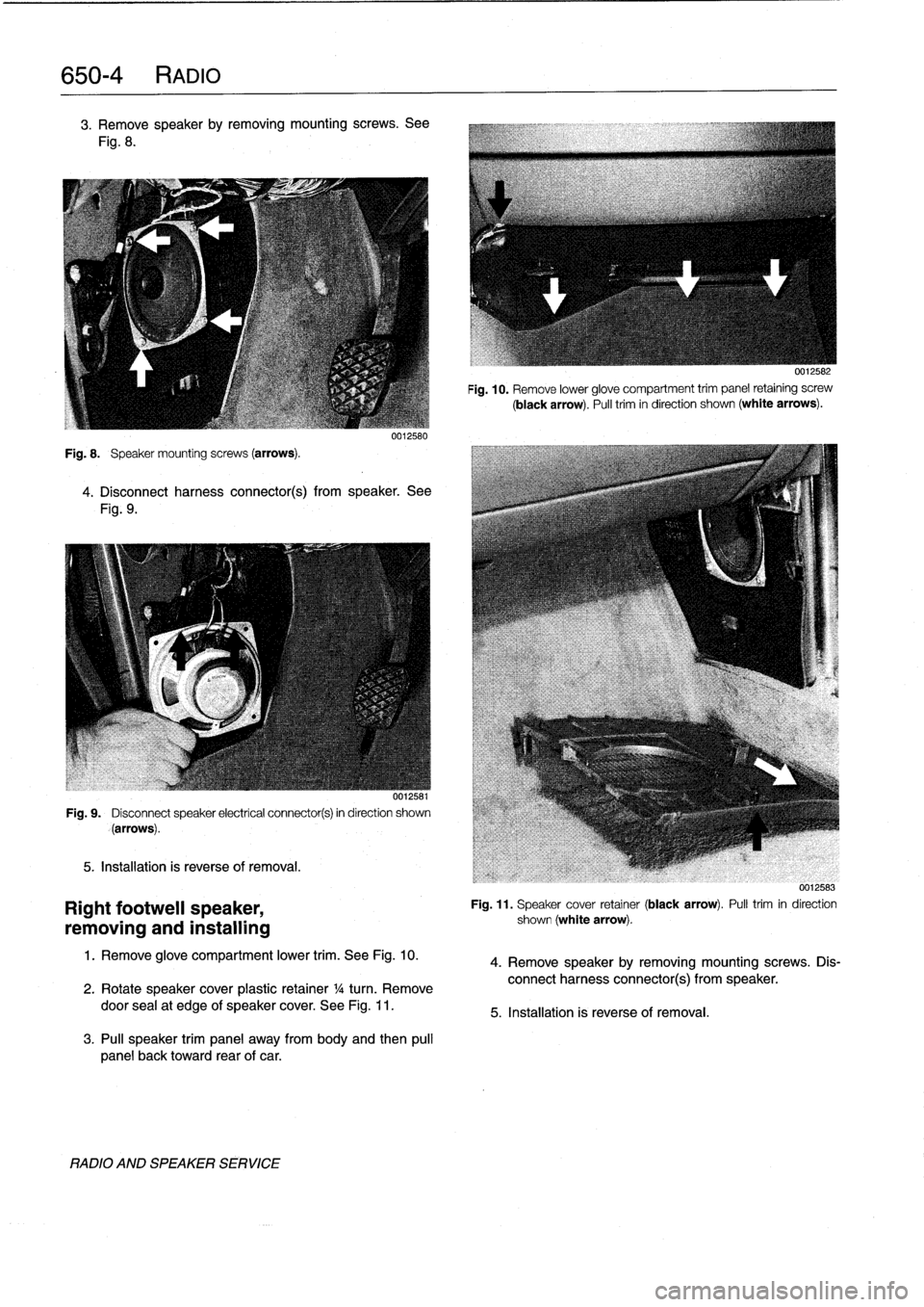
650-
4
RADIO
3
.
Remove
speakerby
removing
mountingscrews
.
See
Fig
.
8
.
Fig
.
8
.
Speaker
mounting
screws
(arrows)
.
0012580
4
.
Disconnect
harness
connector(s)
from
speaker
.
See
Fig
.
9
.
001,58
Fig
.
9
.
Disconnect
speaker
electrical
connector(s)
in
direction
shown
(arrows)
.
5
.
Installation
is
reverse
of
removal
.
Right
footwell
speaker,
removing
and
installing
1
.
Remove
glove
compartment
lower
trim
.
See
Fig
.
10
.
2
.
Rotate
speakercover
plastic
retainer
1
/a
turn
.
Remove
door
sea¡at
edge
of
speaker
cover
.
See
Fig
.
11
.
3
.
Pul¡
speaker
trim
panel
away
from
body
and
then
pul¡
panel
back
toward
rear
of
car
.
RADIO
AND
SPEAKER
SERVICE
0012582
Fig
.
10
.
Remove
lower
glove
compartment
trim
panel
retaining
screw
(black
arrow)
.
Pull
trim
in
direction
shown
(white
arrows)
.
0012583
Fig
.
11
.
Speaker
cover
retainer
(black
arrow)
.
Pulltrim
in
direction
shown
(white
arrow)
.
4
.
Remove
speaker
by
removing
mountingscrews
.
Dis-
connect
harness
connector(s)
from
speaker
.
5
.
Installation
is
reverse
of
removal
.