Computer BMW 325i 1993 E36 Owner's Manual
[x] Cancel search | Manufacturer: BMW, Model Year: 1993, Model line: 325i, Model: BMW 325i 1993 E36Pages: 759
Page 416 of 759
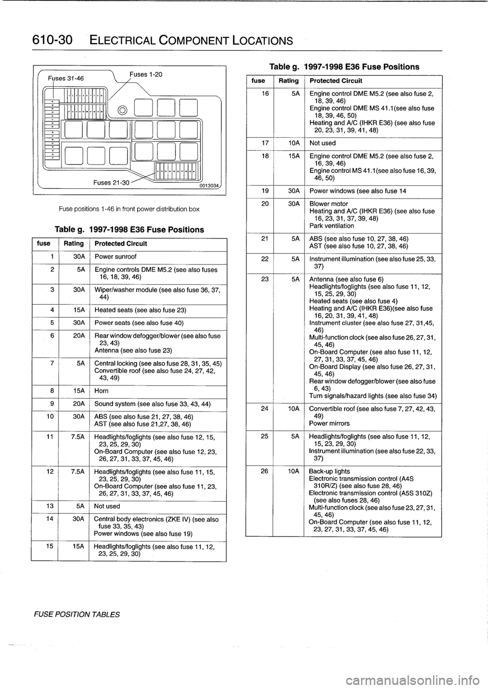
610-30
ELECTRICAL
COMPONENT
LOCATIONS
Fuses
31-46
v
--------------
15A
I
Horn
Fuses21-30
Fuses
1-20
Fuse
positions
1-46
in
front
power
distribution
box
Tableg
.
1997-1998
E36
Fuse
Positions
fuse
Rating
Protected
Circuit
1
I
30A
I
Power
sunroof
4
1
15A
1
Heated
seats
(see
also
fuse
23)
5
1
30A
1
Power
seats
(see
also
fuse
40)
10
30A
ABS
(see
also
fuse
21,27,38,
46)
AST
(see
alsofuse21,27,
38,
46)
13
I
5A
I
Not
used
FUSE
POSITION
TABLES
0013034
2
I
5A
Engine
controls
DME
M5
.2
(see
also
fuses
16,18,
39,
46)
30A
Wiper/washer
module
(seealso
fuse
36,37,44)
20A
~
Rear
window
defogger/blower
(see
also
f
use23,43)
Antenna
(see
also
fuse
23)
5A
~
Central
locking
(seealso
fuse
28,31,35,
45)
Convertible
roof
(see
also
fuse
24,
27,42,
43,49)
9
1
20A
1
Sound
system
(see
also
fuse
33,43,
44)
11
7
.5A
Headlights/foglights
(see
also
fuse
12,15,
23,
25,29,
30)
On-Board
Computer
(see
also
fuse
12,23,
26,
27,31,33,
37,45,
46)
12
7
.5A
Headlights/foglights
(see
also
fuse
11,15,
23,
25,29,
30)
On-Board
Computer
(see
also
f
use
11,23,
26,27,
31,33,
37,45,
46)
14
I
30A
~
Central
body
electronics
(ZKE
IV)
(see
also
fuse
33,
35,43)
Power
windows
(seealso
f
use
19)
15
15A
Headlights/foglights
(see
alsofuse
11,
12,23,25,
29,
30)
Tableg
.
1997-1998
E36
Fuse
Positions
fuse
1
Rating
1
Protected
Circuit
16
5A
Engíne
control
DME
M5
.2
(see
alsofuse
2,
18,39,
46)
Engine
control
DME
MS
41
.1
(see
also
fuse
18,39,46,
50)
Heating
andA/C
(IHKR
E36)
(see
also
fuse
20,
23,31,39,41,
48)
17
I
10A
1
Not
used
18
15A
Engine
control
DME
M5
.2
(seealso
fuse
2,
16,39,
46)
Engine
control
MS
41.1(seealso
fuse
16,
39,
46,50)
19
1
30A
j
Power
windows
(seealsofuse
14
20
30A
Blowermotor
Heating
andA/C
(IHKR
E36)
(see
also
fuse
16,
23,
31,37,39,
48)
Park
ventilation
21
5A
ABS
(seealso
f
use
10,
27,38,
46)
AST
(see
also
fuse
10,27,38,
46)
22
5A
Instrument
illumination
(see
also
f
use
25,
33,
37)
23
5A
Antenna
(see
also
fuse
6)
Headlights/foglights
(see
also
fuse
11,
12,
15,
25,
29,
30)
Heated
seats
(see
also
fuse
4)
Heating
andA/C
(IHKR
E36)(see
also
fuse
16,
20,
31,39,41,
48)
Instrument
cluster
(seealso
f
use
27,
31,45,
46)
Multi-function
clock
(seealsofuse
26,27,31,
45,46)
On-Board
Computer
(see
also
fuse
11,12,27,
31,
33,37,45,
46)
On-Board
Display
(seealsofuse
26,27,
31,
45,46)
Rear
window
defogger/blower
(see
also
f
use6,43)Turn
signals/hazard
lights
(seealsofuse
34)
24
10A
~
Convertible
roof
(see
also
f
use
7,
27,42,43,
49)
Power
mirrors
25
5A
Headlights/foglights
(seealso
fuse
11,12,
15,23,
29,30)
Instrument
illumination
(seealso
fuse
22,33,
37)
26
10A
Back-up
lights
Electronic
transmission
control
(A4S
310R/Z)
(see
also
f
use
28,
46)
Electronic
transmission
control
(A5S
310Z)
(see
also
fuses
28,46)
Multi-function
clock
(see
also
fuse
23,
27,
31,
45,46)
On-Board
Computer
(see
alsofuse
11,
12,
23,
27,31,33,37,45,
46)
Page 417 of 759
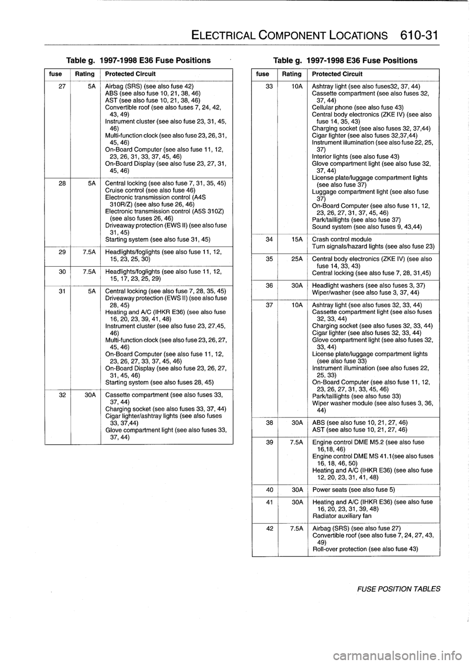
Table
g
.
1997-1998
E36
Fuse
Positions
Table
g
.
1997-1998
E36
Fuse
Positions
fuse
1
Rating
1
Protected
Circuit
27
5A
Airbag
(SRS)
(seealsofuse
42)
ABS
(see
also
fuse
10,21,38,
46)
AST
(see
alsofuse
10,
21,
38,
46)
Convertible
roof
(see
also
fuses
7,
24,
42,
43,49)
Instrument
cluster
(see
alsofuse
23,31,
45,46)
Multi-function
clock
(see
also
fuse
23,
26,
31,
45,46)
On-Board
Computer
(see
alsofuse
11,12,23,26,31,33,37,45,
46)
On-Board
Display
(see
also
f
use
23,27,
31,
45,46)
28
5A
Central
locking
(see
also
fuse
7,
31,35,
45)Cruise
control
(see
also
fuse
46)
Electronic
transmission
control
(A4S
310R/Z)
(seealso
f
use
26,
46)
Electronic
transmission
control
(A5S
310Z)
(seealso
(uses
26,
46)
Driveaway
protection
(EWS
II)
(see
also
fuse
31,45)
Starting
system
(seealsofuse
31,
45)
29
7
.5A
Headlights/foglights
(seealsofuse
11,
12,15,23,
25,
30)
30
7
.5A
Headlights/foglights
(seealsofuse
11,
12,15,
17,
23,25,
29)
31
5A
Central
locking
(seealsofuse
7,
28,
35,
45)
Driveaway
protection
(EWS
II)
(see
also
fuse
28,45)
Heating
andA/C
(IHKR
E36)(see
also
fuse
16,20,23,39,41,
48)
Instrument
cluster
(see
alsofuse
23,
27,45,
46)
Multi-function
clock
(see
alsofuse
23,26,27,
45,46)
On-BoardComputer
(seealsofuse
11,12,23,26,27,33,37,
45,46)
On-Board
Display
(seealso
f
use
23,
26,
27,31,45,46)
Starting
system
(see
also
fuses
28,
45)
32
30A
Cassette
compartment
(seealso
f
uses
33,
37,44)Charging
socket
(see
also
fuses
33,37,
44)
Cigar
lighter/ashtray
lights
(seealso
f
uses
33,37,44)
Glove
compartment
light
(see
also
fuses
33,
37,44)
ELECTRICAL
COMPONENT
LOCATIONS
610-31
fuse
1
Rating
1
Protected
Circuit
33
10A
Ashtray
light
(seealso
fuses32,
37,
44)
Cassette
compartment
(seealso
fuses
32,
37,44)
Cellular
phone
(seealso
fuse
43)
Central
body
electronics
(ZKE
IV)
(seealsofuse
14,
35,
43)
Charging
socket
(seealso
fuses
32,
37,44)
Cigar
lighter
(seealso
fuses
32,37,44)
Instrument
illumination
(see
also
fuse
22,
25,37)
Interior
¡ights
(seealso
fuse
43)
Glove
compartment
light
(see
also
fuse
32,
37,44)
License
plate/luggage
compartment
lights
(see
also
fuse
37)
Luggage
compartment
light
(seealso
f
use
37)
On-BoardComputer
(see
also
f
use
11,12,
23,26,
27,
31,37,45,
46)
Park/taillights
(seealsofuse
37)
Sound
system
(seealso
fuses
9,
43,44)
34
15A
Crash
control
module
Turn
signals/hazard
lights
(see
alsofuse
23)
35
25A
~
Central
body
electronics
(ZKE
IV)
(see
also
fuse
14,
33,
43)
Central
locking
(see
also
f
use
7,
28,
31,45)
36
30A
Headlight
washers
(see
also
fuses
3,
37)
Wiper/washer
(seealsofuse
3,
37,
44)
37
10A
Ashtray
light
(see
also
(uses
32,33,
44)
Cassette
compartment
light
(seealso
fuses
32,
33,
44)
Charging
socket
(see
also
fuses
32,
33,44)
Cigar
lighter
(see
also
f
uses
32,33,
44)
Glove
compartment
light
(see
also
fuses
32,
33,44)
License
plate/luggage
compartment
lights
(seealso
f
use
33)
Instrument
illumination
(seealso
fuses
22,
25,33)
On-Board
Computer
(seealsofuse
11,12,23,
26,
27,31,33,
45,
46)
Park/taillights
(see
alsofuse
33)
Wiper
washer
module
(see
also
f
uses
3,
36,
44)
38
30A
ABS
(seealsofuse
10,
21,
27,
46)
AST
(see
also
fuse
10,21,27,
46)
39
7
.5A
Engine
control
DME
M5
.2
(see
also
fuse
16,18,
46)
Engine
control
DME
MS
41
.1
(seealso
fuses
16,18,46,
50)
Heating
andA/C
(IHKR
E36)
(see
alsofuse
12,20,23,31,
41,48)
40
30A
Power
seats
(seealsofuse
5)
41
30A
~
Heating
andA/C
(IHKR
E36)
(see
alsofuse
16,20,23,
31,
39,
48)
Radiator
auxiliary
fan
42
7
.5A
Airbag
(SRS)
(seealsofuse
27)
Convertible
roof
(seealso
f
use
7,
24,27,43,
49)
Rol¡-over
protection
(seealso
f
use
43)
FOSE
POSITION
TABLES
Page 418 of 759
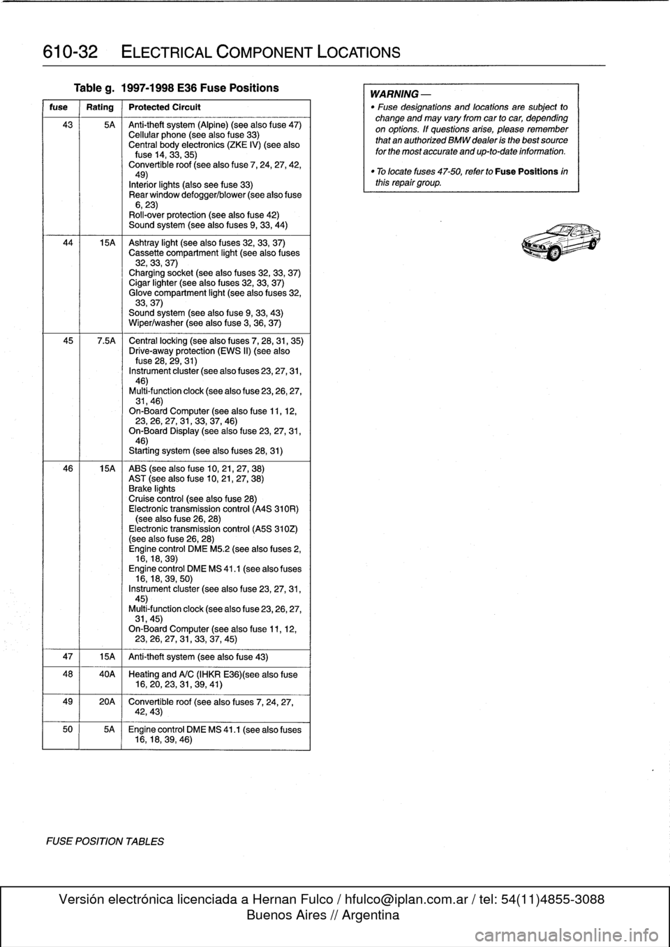
610-32
ELECTRICAL
COMPONENT
LOCATIONS
Tableg
.
1997-1998
E36
Fuse
Positions
fuse
Rating
Protected
Circult
43
5A
Anti-theft
system
(Alpine)
(see
also
f
use47)
Cellular
phone
(seealso
fuse
33)
Central
body
electronics
(ZKE
IV)
(see
alsofuse
14,
33,35)
Convertible
roof
(seealso
fuse
7,
24,
27,
42,49)
Interiorlights
(also
see
fuse
33)
Rear
window
defogger/blower
(see
alsofuse
6,23)
Roll-over
protection
(see
also
fuse
42)
Sound
system
(seealso
fuses
9,
33,
44)
44
15A
Ashtray
light
(seealso
f
uses
32,
33,
37)
Cassette
compartment
light
(seealso
fuses
32,33,
37)
Charging
socket
(seealso
fuses
32,33,
37)
Cigar
lighter
(seealso
fuses
32,33,
37)
Glove
compartment
light
(seealso
f
uses
32,
33,37)
Sound
system
(seealsofuse
9,
33,
43)
Wiper/washer
(seealsofuse
3,
36,
37)
45
7
.5A
Central
locking
(see
also
fuses
7,
28,31,
35)
Drive-away
protection
(EWS
II)
(see
alsofuse
28,
29,31)
Instrument
cluster
(see
also
f
uses
23,27,31,
46)
Multi-function
clock
(see
also
f
use
23,26,27,
31,46)
On-Board
Computer
(see
alsofuse
11,
12,23,
26,27,
31,33,37,
46)
On-Board
Display
(seealsofuse
23,27,31,
46)
Starting
system
(seealso
fuses
28,31)
46
15A
ABS
(see
also
fuse
10,21,27,
38)
AST
(seealsofuse
10,
21,27,
38)
Brake
lights
Cruise
control
(see
also
fuse
28)
Electronic
transmission
control
(A4S
310R)
(see
also
fuse
26,
28)
Electronic
transmission
control
(A5S
310Z)
(see
also
f
use
26,28)
Engine
control
DME
M5
.2
(see
also
fuses
2,
16,18,
39)
Engine
control
DME
MS
41
.1
(seealso
fuses
16,18,39,
50)
Instrument
cluster
(see
also
fuse
23,27,31,
45)
Multi4unction
clock
(see
also
fuse
23,26,27,
31,45)
On-Board
Computer
(seealsofuse
11,
12,23,26,27,
31,
33,37,
45)
47
1
15A
1
Anti-theft
system
(see
also
fuse
43)
48
40A
Heating
and
A/C
(IHKR
E36)(see
also
fuse
16,20,23,
31,
39,
41)
49
20A
Convertible
roof
(see
also
fuses
7,
24,
27,
42,43)
50
5A
Engine
control
DME
MS
41
.1
(seealso
fuses
16,18,39,
46)
FUSE
POSITION
TABLES
WARNING
-
"
Fuse
designations
and
locations
are
subject
to
change
and
may
vary
fromcar
to
car,
depending
on
options
.
If
questions
arise,
please
remember
that
an
authorized
BMW
dealer
is
the
bestsource
for
the
most
accurate
and
up-to-date
information
.
"
Tolocate
fuses
47-50,
refer
to
Fuse
Positions
inthis
repair
group
.
Page 440 of 759
620-
4
INSTRUMENTS
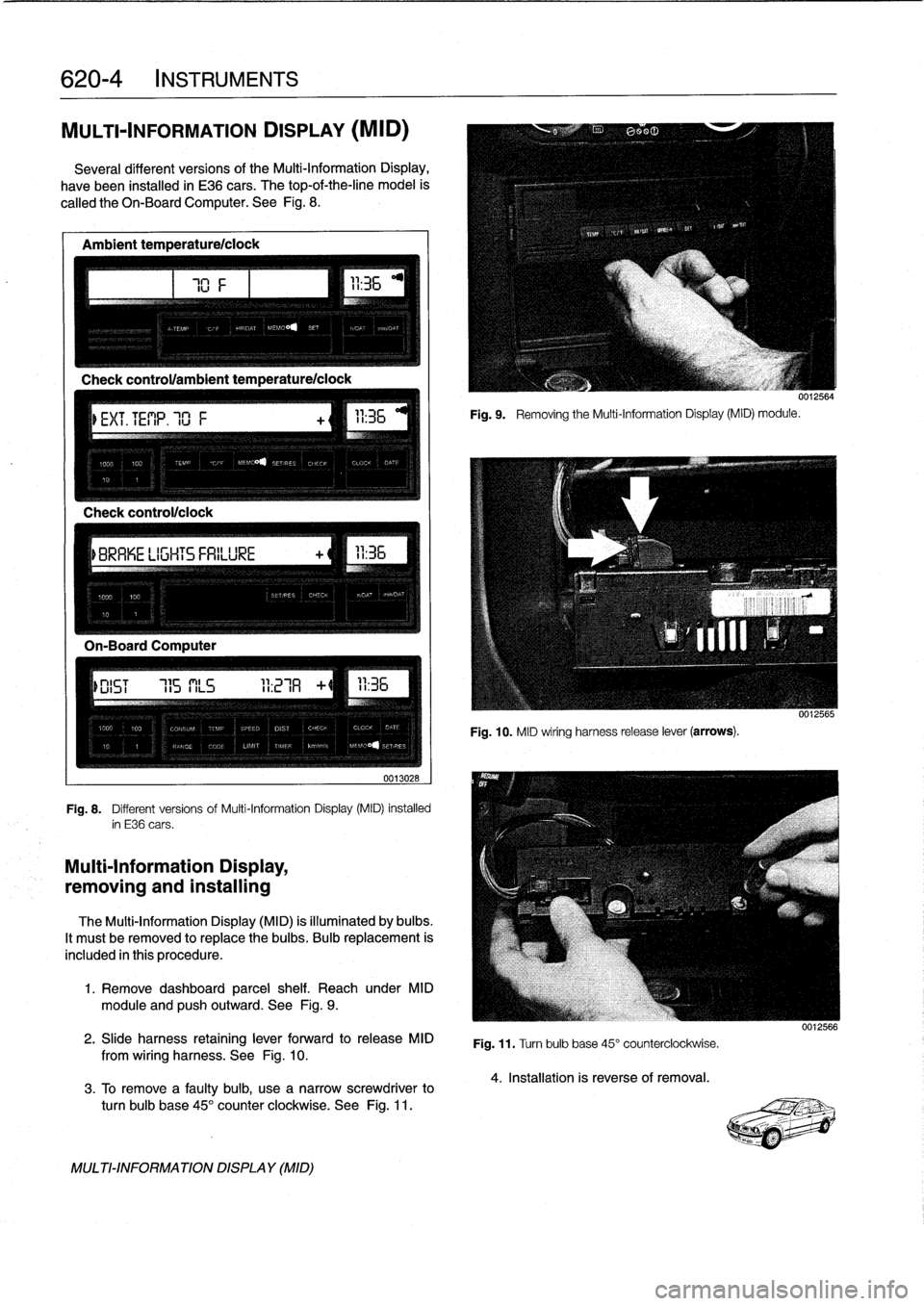
MULTI-INFORMATION
DISPLAY
(MID)
Severa¡
different
versionsof
the
Multi-Information
Display,
have
been
installed
in
E36
cars
.
The
top-of-the-line
model
is
called
the
Oh-BoardComputer
.
See
Fig
.
8
.
Ambient
temperature/ciock
Check
control/clock
0013028
Fig
.
8
.
Different
versions
of
Multi-Information
Display
(MID)
installed
in
E36
cars
.
Multi-Information
Display,
removing
and
installing
The
Multi-Information
Display
(MID)
is
illuminated
by
bulbs
.
It
mustbe
removed
to
replace
the
bulbs
.
Bulb
replacement
is
included
in
this
procedure
.
1
.
Remove
dashboard
parcel
shelf
.
Reach
under
MID
module
and
pushoutward
.
See
Fig
.
9
.
2
.
Slide
harness
retaining
lever
forward
to
release
MID
from
wiring
harness
.
See
Fig
.
10
.
3
.
To
Rmove
a
faulty
bulb,
use
anarrow
screwdriver
to
turn
bulb
base
45°
counter
clockwíse
.
See
Fig
.
11
.
MULTI-INFORMATIONDISPLAY
(MID)
111
Fig
.
9
.
Removing
the
Multi-Information
Display(MID)
module
.
0012564
Fig
.
10
.
MID
wiring
harness
release
lever
(arrows)
.
Fig
.
11
.
Turn
bulb
base
45°
counterclockwise
.
4
.
Installation
is
reverse
of
removal
.
0012566
Page 485 of 759
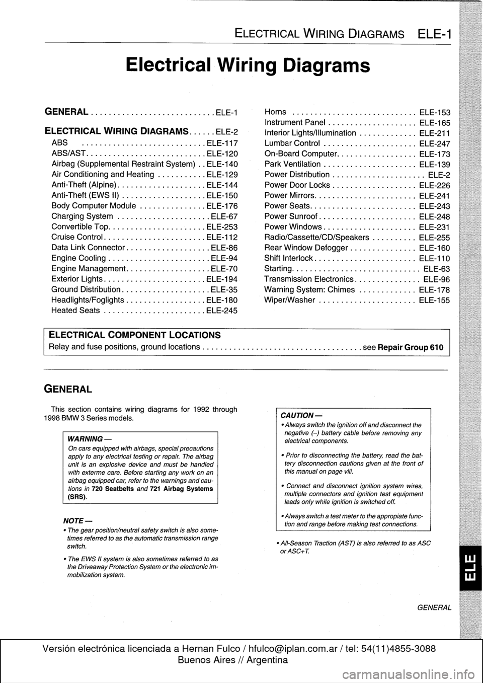
GENERAL
This
section
contains
wiring
diagrams
for
1992
through
1998
BMW
3
Series
models
.
WARNING
-
On
cars
equipped
with
airbags,
special
precautions
apply
to
any
electrical
testing
or
repair
.
The
airbag
unit
is
an
explosive
device
and
must
be
handled
with
exterme
care
.
Before
starting
any
work
onan
airbag
equipped
car,
refer
to
the
warnings
and
cau-
tions
in
720
Seatbelts
and
721
Airbag
Systems
(SRS)
.
NOTE-
The
"
gear
position/neutral
safetyswitch
is
also
some-
timesreferred
to
as
the
automatic
transmission
range
switch
.
"
The
EWS
11
system
is
also
sometimes
referred
to
as
the
Driveaway
Protection
System
or
the
electronic
im-
mobilization
system
.
ELECTRICAL
WIRING
DIAGRAMS
ELE-1
Electrical
Wiring
Diagrams
GENERAL
.
.
.
.
.
.
.
.
.
................
.
.
.
ELE-1
Horns
.....
.
.....
.
.
.
....
.
.
.
.
.
...
.
.
ELE-153
Instrument
Panel
.
.
.
.
.
.
..............
ELE-165
ELECTRICAL
WIRING
DIAGRAMS
...
.
.
.
ELE-2
Interior
Lights/Illumination
.............
ELE-211
ABS
..............
.
.
.
.....
.
.....
ELE-117
Lumbar
Control
.
....................
ELE-247
ABS/AST
.............
.
.
.
...
.
.
.
.....
ELE-120
On-Board
Computer
..................
ELE-173
Airbag
(Supplemental
Restraint
System)
..
ELE-140
Park
Ventilation
.
.
.
...........
.
...
.
..
ELE-139
Air
Conditioning
and
Heating
.
.
.
.
.
.
.....
ELE-129
Power
Distribution
......
.
...
.
.
.
.
.
.
.
...
.
ELE-2
Anti-Theft
(Alpine)
..........
.
.
.
...
.
...
ELE-144
Power
Door
Locks
.
.
......
.
.
.
.
.
.
.
.
.
..
ELE-226
Anti-Theft
(EWS
II)
.
........
.
.
.
...
.
...
ELE-150
Power
Mirrors
...
.
.
.
......
.
.
.
.
.
.
.
.
.
..
ELE-241
Body
Computer
Module
.....
.
.....
.
...
ELE-176
Power
Seats
......
.
......
.
.
.
...
.
.
.
..
ELE-243
Charging
System
.
.
................
.
.
.
ELE-67
Power
Sunroof
.
.
.
.
.
.
.
...............
ELE-248
Convertible
Top
.
.
.
.
................
.
.
ELE-253
Power
Windows
.
.
.
.
.
.
.....
.
.........
ELE-231
Cruise
Control
..
.
.
.
...........
.
....
.
.
ELE-112
Radio/Cassette/CD/Speakers
..........
ELE-255
Data
Link
Connector
................
.
.
.
ELE-86
Rear
Window
Defogger
...............
ELE-160
Engine
Cooling
.......
.
.......
.
....
.
.
.
ELE-94
Shift
Interlock
.
.
.
.
.
.
.
.
...............
ELE-110
Engine
Management
...
.
.......
.
....
.
.
.
ELE-70
Starting
....
.
.
.
.
.
...
.
................
ELE-63
Exterior
Lights
........
.
.
.
.
.
.
.
.
.
......
ELE-194
Transmission
Electronics
.
..............
ELE-96
Ground
Distribution
....
.
.
.
.
.
.
.
.
.
.......
ELE-35
Warning
System
:
Chimes
.............
ELE-178
Headlights/Foglights
...
.
.
.
.
.
.
.
.
.
......
ELE-180
Wiper/Washer
.
.....
.
...............
ELE-155
Heated
Seats
........
.
.
.
.
.
.
.
.
.
......
ELE-245
ELECTRICAL
COMPONENT
LOCATIONS
Relayand
fuse
positions,
ground
locations
...........
.
.
.
.
.
.
.
.
.
................
seeRepair
Group
610
CAUTION-
Always
switchthe
ignition
off
and
disconnect
the
negative
(-)
battery
cablebefore
removing
any
electrical
components
.
"
Prior
to
disconnecting
the
battery,
read
the
bat-tery
disconnection
cautions
given
at
the
front
of
this
manual
on
page
viii
.
"
Connect
and
disconnect
ignition
system
wires,
multiple
connectors
and
ignition
test
equipment
leads
only
while
ignition
is
switched
off
.
-Always
switch
a
test
meter
to
the
appropiate
func-
tion
and
range
before
making
test
connections
.
"
All-Season
Traction
(AST)
is
also
referred
to
as
ASC
or
ASC+T
.
GENERAL
Page 486 of 759
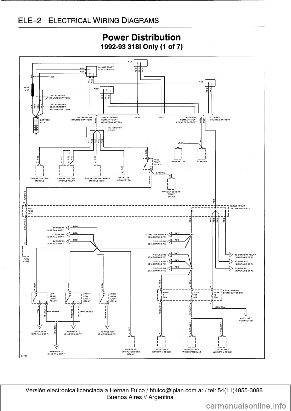
ELE--2
ELECTRICAL
WIRING
DIAGRAMS
FUSE
LINK
64766
I-i
I
-
i
a
1
I
_
ZJ
I
I
I
I
I
I.
4
2
GRN/VIO
I_I
!
___I
I_I
1
D>
6
END
INECONTROL
ENGINECONTROL
TRANSMISSION
CONTROL
DATALINK
MODULE
MODULE
RELAY
MODULE
(EGS)
CONNECTOR
I
I
I
I
5
(F18
--_______________________________________________
O19~
N
RIBUON
BOX
I
FUSE
II
15A
o~___________________________________________________Q~____-aft
TO
FUSE
F5
C
RED
(DIAGRAM
6
OF
7)
FUELPUMP
I
(DIAGRAM60F7)
C'
RED
\
L------r>
(DIAGRAM60F7)
I
LOW
F
I
FRONT
HIGH
BEAM
FOGJ
BEAM
I
I
LIGHT
I
I
LIGHT
I
j
/
I
LIGHT
RELAY
I
RELAY
li
SJ
RELAY
1992
1993W/TRUNK
MOUNTEDBATTERV
1993W/ENGINE
COMPARTMENTMOUNTEDBATTERV
1993W/TRUNK
1993W/ENGINE
1992
1992
WI
ENGINE
W/TRUNK
BATTERY
MOUNTEDBATTERV
¢)
MOUNTED
BATTERY
MOUN
O
TEDBATT
I
ERV
¢I¢I
MOUNTEDBATTERV
TOFUSEF40
<
,.k
RED
(DIAGRAM
6
OF
7)
I
I
(DIAGRAM
3
OF
7)
TO
FUSEF3
E
RED
(DIAGRAMfiOF7)
"
.
1k
I
(DIAGRAM
6OF7)
>I
mJ~CANADA
RED
BNUMPSTART
JUNCTION
POINT
REO
Power
Distribution
1992-93
318i
Only
(1
of
7)
-UNCTION
POINT
TOFUSEF15
TO
FUSE
F29
(DIAGRAM60F7)
(OIAGRAM6OF7)
I
~1
.
FUEL
_I
I
_I
~
(PUMP
GENERATOR
STARTER
I
,(
I
RELAY
TO
IGNITION
SWITCH
QA
TOFUSE
F20
TOFUSEF19
FRED
(DIAGRAM6OF7)
`
I
III
-
(DIAGRAM70F7)
OXVGENSENSOR
RELAY
(4CVL)
RED
RED
RED
ON-BOARD
LEFTPOWERRIGHTPOWERLEFTPOWER
TOFUSEF17
COMPUTERHORN
WINDOWMODULE
WINDOWMODULE
WINDOW
MODULE
(DIAGRAM
60F
7)
RELAY
TO
COMFORTRELAV
Page 487 of 759
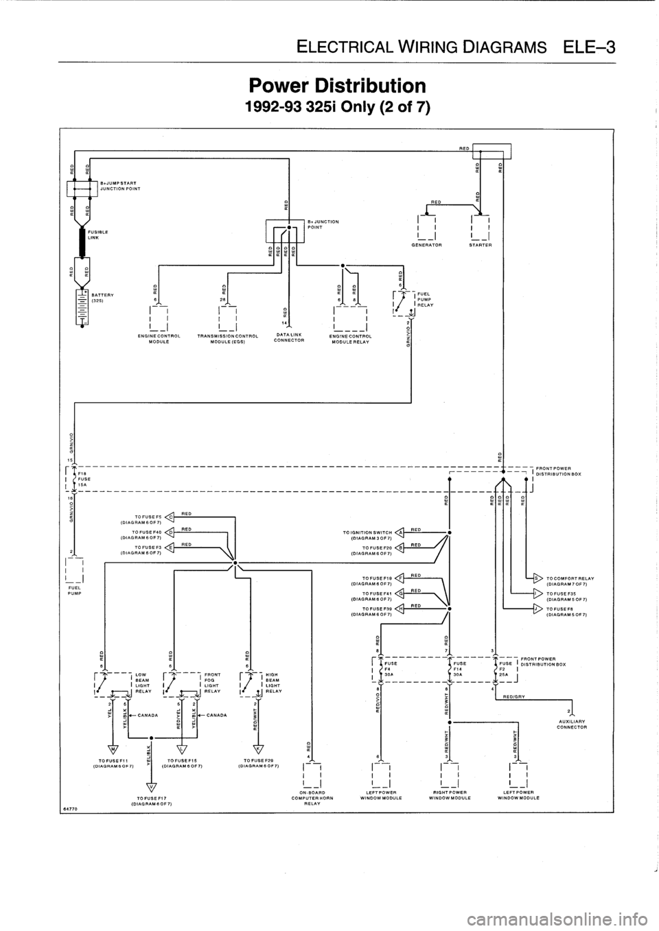
ELE
Power
L
1992-9332
RED
E01
IIIII
FUSIBLE
LINK
I
GENERATOR
STARTER
BATTERY
¢
(FUEL
-
(325)
S
26
66
PUMP
I
I
RELAY
2
G
ENGINE
CONTROL
TRANSMISSION
CONTROL
DATA
LINK
ENGINECONTROL
iMODULE
MODULE
(EGG)
CONNECTOR
MODULE
RELAY
15
--
---
-
-
----
--
FRONT
POWER
FUSE
r
-
i
DISTRIBUTIONBO
;
I
16A
R
ITIT
TO
FUSE
FS
ED
C
(DIAL
RAM
6
OF
7)
TO
FUSE
F40
D
RED
TO
IGNITION
SWITCH
A
RED
(DIAGRAM
6
OF
7)
(DIAGRAM
3
OF
7)
TO
FUSE
F3
E
RED
TO
FUSE
F20
B
RED
2
(DIAGRAM6OF7)
(DIAGRAM
6OF7)
I
I
I
I
-
I
TOFUSEF19
:
:!!RED---
RED
S
TOCOMFORTI
(DIAGRAM
6
OF
7)
(DIAGRAM
70
FUEL
PUMP
TO
FUSE
F41
V\
TOFUGEF35
(DIAGRAM
B
OF
7)
\
(DIAGRAM
50
TOFUSEFSB
H
RED
"
J
TOFUSEF
.
(DIAGRAM
6
0F
7)
(DIAGRAM
50
8
7
3
FUGE
FUSE
FUSE
I
FRONT
POWER
B
6
6
DISTRIBUTION
BOX
F4
F14
F2
I
LOW
FRONT
HIGH
I
30A
30A
~
.1
.
25A
BEAM
F
I
FOG
F
(
BEAM
i
_________
_____
J
I
I
LIGHT
I
I
LIGHT
I
.
I
LIGHT
l
RELAY
I
-
RELAY
I
-
WJ
_RELAY
6
B
4
-
-
-
O
RED/GRY
3
21
2
B
62
2
~
-
CANADA
j
m
-CANADA
3
"
AUXILIAI
CONNECT
"
3
3
M
L
K
4(D
IAGAGR
AM60
F7)
(DIAGRAM
IAGRAM
B
OFOF
7)
(DIAGRAM
6
0
6
3
3G
FO
F
~
7)
I
I
I
I
I
II
I
I
I
I
I
I
I
!
_I
!
_I
!
_I
!
_
17
I
ON-BOARD
LEFTPOWER
RIGHTPOWER
LEFT
POWERTOFUSEFI7
COMPUTERHORN
WINDOW
MODULE
WINDOWMODULE
WI
NDOWMODULE
(DIAGRAMS
OF7)
RELAY
64770
Page 489 of 759
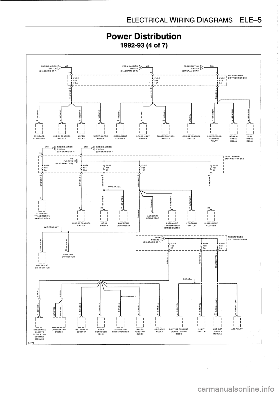
EKE
Power
1992-
VIO
FROMIGNITION
U
VIO
FROM
IGNITI
ON
SWITCH
SWITCH
2S
(DIAGRAM3OF7)
31
(DIAGRAM3OF7)
I
-
______________-__________--
4
-_____________________I_-FRONT
POWER
O
3
3
3
3
i
14
8
8
B
18
7
26
-
4
4
I
i
I
I
i
-F-
I
i
I
-
,
I
,
I
I
F-,
ON
-BOARD
CHECKCONTROL
WIPER
WIPER
MOTOR
INSTRUMENT
BRAKELIGHT
CRUISE
CONTROL
CRUISE
CONTROL
COMPRESSOR
NORMALCOMPUTER
MODULE
RELAYRELAY
CLUSTER
SWITCH
MODULE
SWITCH
CONTROL
SPEEDRELAYRELAY
GRN
0
FROM
IGNITION
GRN
P
FROM
IGNITION
~I
I
VSWITCH
SWITCH
(DIAGRAM
30F7)
,~
(DIAGRAM
3OF7)
-------_-_____________________________________________~FRONT
POWER
TO
I
DISTRIBUTIONBOX
FUSE
F23
G
(DIAG
RAM
4
0F
7)
I
FUSE
FUSE
FUSE
FUSE
FUSE
'
F26
F24
F25
F26
-
F27
6A
10A
SA
ICA
5A
is
S
,0
12
,4
o3
>
CANADA
5
I
~
~
~
3
33
-
2
22
B
F
O
2
5
23
AUTOMATIC
I
I
I
3
1
I
TRANSMISSION
AUXILIARY
RANGESWITCH
I
-
I
I
-
I
I
-
I
CONNECTOR
MIRRORCONTROL
LIGHT
LOWBEAM
AUTOMATIC
PROGRAM
INSTRUMENT
SWITCHSWITCH
LIGHTRELAY
TRANSMISSION
SWITCH
CLUSTER
WIOEGSONLY
RANGESWITCH
FROM
___________-----1FRONTPOWER
FUSEF24
CI
DISTRIBUTION
BC
3
(DIAGRAM30F7)
FUSE
FUSEFUSE
F23
F22
F21
O
O
SA
SA
5A
DATA
LINK
6
j
2
I
CONNECTOR
REVERSING
LIGHTSWITCH
CANADA
O
"
-1993
ONLY
O4
4
4
1
S
B
3
B
53
4
I
v
I~
i
I
i
I
v
I
i
I
v
I
i
I
v
I
i
I
i
I
i
v
v
v
v
~
v
v
~
~
v
v
~
v
v
o
n
v
v
v
v
v
v
_I
INTEGRATED
COMBINATION
INSTRUMENT
REAR
JETHEATER
MULTI-
UNLOADER
DAYTIMERUNNING
LIGHT
ASSSLIP
ABSRELAY
CLIMATE
SWITCH
CLUSTER
DEFOGGER
THERMOSWITCH
FUNCTION
RELAY
LIGHTSCODING
SWITCH
CONTROL
REGULATION
RELAY
CLOCK
DIODE
MODULE
CONTROL
MODULE
64776
Page 495 of 759
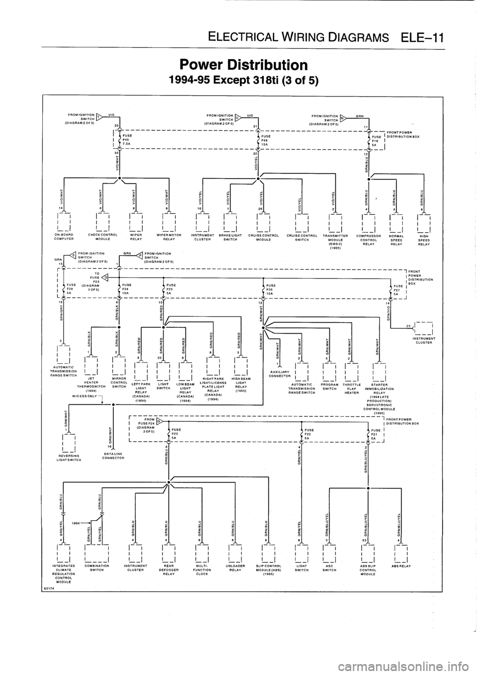
8317
4
FROMIGNITION
T
VIO
FROM
IGNITION
U
VIO
"I"
IGNITION
SWITCH
SWITCH
SWITCH
(DIAGRAM2OF5)
29
(DIAGRAM20F5)
31
(DIAGRAM20F5)
FROMIGNITION
GRIN
PROMIGNITION
SWITCH
SWITCH
(DIAGRAM20F5)
~(DIAGRAM20F5)
REVERSING
LIGHT
SW
TO
DATA
LINK
CONNECTOR
Power
Distribution
1994-95
Except
318ti
(3
of
5)
______________________________________________
-_-
FRONTPOWER
ELECTRICAL
WIRING
DIAGRAMS
ELE-11
3
FUSE
FUSE
I
DISTRIBUTION
BOX
F46
F18
I
L
>
t
141
6'
81
81
16/
11
261
j
2
4
q
I
I
I
I
I
I
I
i
I
Jll~~~
i
I
It
i
I
JJJ
...
i
-
i
-
i
-
i
-
i
--
I
I
I
1
I
II
I
I
I
I
I
I
I
I
I
I
I
I
I
I
I
I
I
I
I
I
I
I
I
ON-BOARD
CHECKCONTROL
WIPER
WIPERMOTOR
INSTRUMENT
BRAKELIGHT
CRUISE
CONTROL
CRUISECONTROL
TRANSMITTER
COMPRESSOR
NORMAL
HIGH
COMPUTERMODULE
RELAY
RELAY
CLUSTER
SWITCH
MODULE
SWITCH
MODULE
CONTROL
SPEEDSPEED
(EWSIN
RELAYRELAYRELAY
(1995)
,FRONT
(POWER
DISTRIBUTION
FUSE
FUSE
FUSE
(BOX
FUSE
I
F24
F25
F26
F27
10A
5A
10A
5q
I
------------------
-
-------
-
I
I
I
I
I
I
I
I
I
I
I
I
I
I
'
I
I
I
I
I
I
I
I
AUTOMATIC
"1"
TRANSMISSION
I
-
I
I
_
I
I
_
I
I
I
I
I
I
-)
I
_
I
AUXILIARY
RANGESWITCH
JETMIRROR
L
II
CONNECTORCONNECTOR
RIG
H7
PARK
HIGH
BEAM
I
I
I
I
HEATER
CONTROL
LEFT
PARK
LIGHT
LOWBEAM
LIGHT/LICENSE
LIGHT
AUTOMAT
IC
PROGRAM
THROTTLE
SWITCH
LIGHT
SWITCH
LIGHT
PLATE
LIGHT
RELAY
HROTTLE
STARTER
(
(1995)
TRANSMISSIONSWITCH
FLAP
IMMOBILIZATION
994)
RELAY
RELAYRELAY
A)
RANGESWITCH
HEATER
RELAY
WIOEGSONLV
--
I
-
(CANADA)
(CANADA)
(CANAD
(1994
LATE
(1894)
(1994)
(1
994
)
PRODUCTION)
SERVOTRONIC
CONTROLMODULE
(1995)
FROM
FRONTPOWER
I
FU
SEF24
I
DISTRIBUTIONBOX
I
(DIAGRAM
30F5)
FUSE
FUSE
FUSE
II
F23
F22
F21
I
5A
5A
5A
61
_I-
=
L
41
4,
1
91
8t
el
8),
51
531
I
I
I
I
I
I
I
I
I
I
I
I
I
I
I
I
I
I
I
I
I
i
I
I
I
I
I
I
I
I
I
I
I
I
I
I
I
I
I
I
I
I
I
II
_I
!
---
I
!
_I
!
_I
23
INTEGRATED
COMBINATION
INSTRUMENT
PEAR
MULTI-
UNLOADER
SLIP
CONTROL
LIGHT
ASC
ABSSLIP
ASS
RELAY
CLIMATE
SWITCH
CLUSTER
DEFOGGER
FUNCTION
RELAY
MODULE
(AB
S)
SWITCH
SWITCH
CONTROL
REGULATION
RELAY
CLOCK
(1995)
MODULE
CONTROL
MODULE
INSTRUMENT
CLUSTER
Page 497 of 759
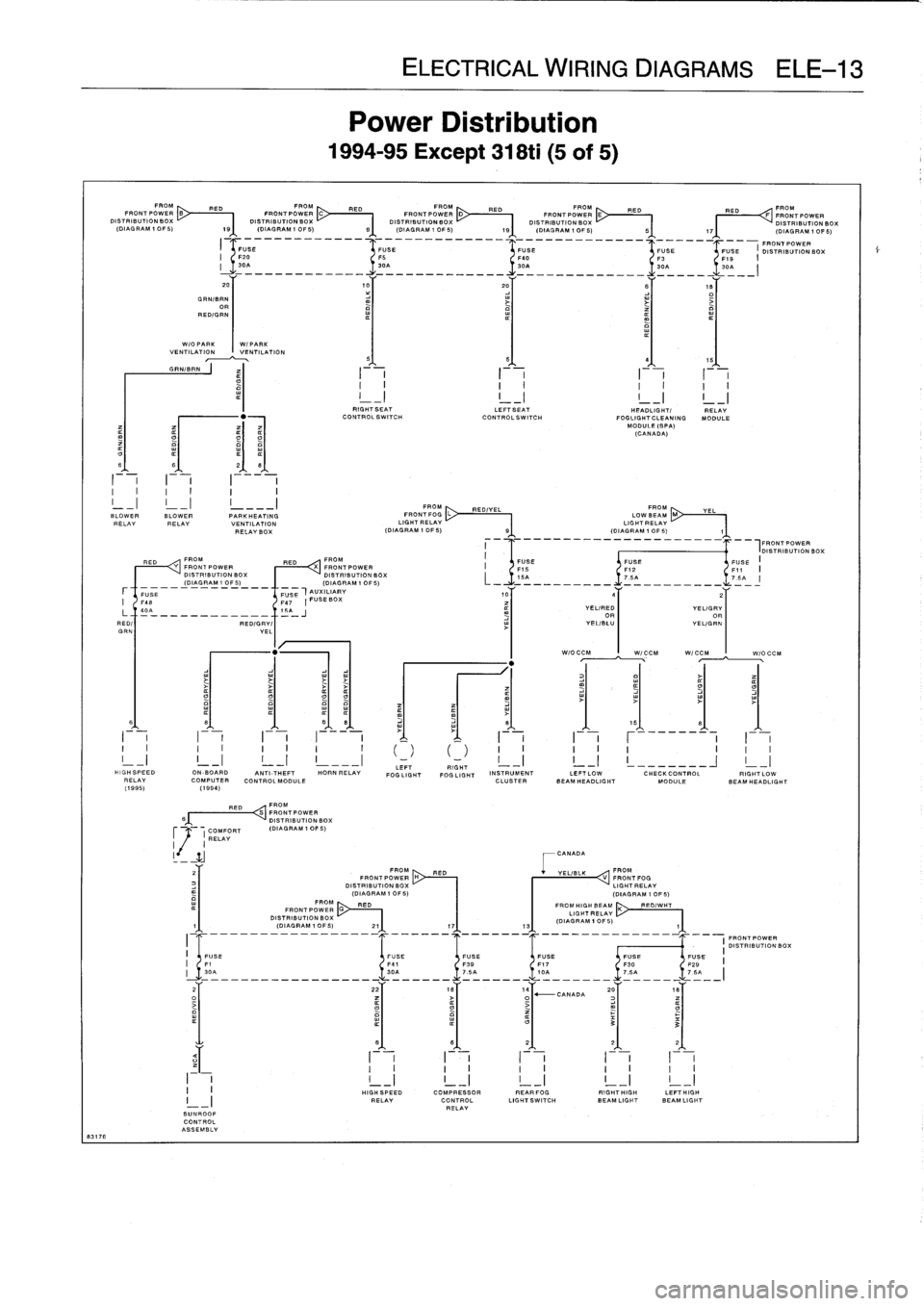
FROM
FROM
FROM
FROM
ER
FROMRED
RED
RED
RED
RED
FRONT
POWER
B
FRONTPOWER
C
FRONT
POWERD
FRONT
POW
E
F
FRONTPOWER
DISTRIBUTION
BOX
O'S
TRIBUTIONBOX
~
DISTRIBUTION
BOX
DISTRIBUTION
BOX
DISTRIBUTION
BOX
(DIAGRAM
IOF5)
19
(DIAGRAM
IOF5)
91
-
(DIAGRAM
IOF5))
---
9
'
-
(DIAGRAM
101S)
17
---
F
a
(DIAGRAM
IOF5)
-
GRN/BRN
OR
RED/GRN
FUSE
F20
FS
30A
30A
---------------
------------
W/O
PARK
I
W/PARK
VENTILATIONVENTILATION
5
I
_I
I
I
_I
I
L
_J
I
!
BLOWER
BLOWER
PARKHEATING
RELAY
RELAY
VENTILATION
RELAYBOX
LI
401
i5_A
J
_____________I_
RED/I
RED/GRY/
GRN
YEL
CONTROL
ASSEMBLY
FROM
FRONTPOWER
DISTRIBUTION
BOX
(DIAGRAM
1
OF5)
RED
FROM
RED
FROM
Y
FRONTPOWER
X
FRONT
POWER
DISTRIBUTION
BOX
DISTRIBUTIONBOX
(DIAGRAMIOF5)(DIAGRAM10F5)
FUSE
FUSE"
AUXILIARY
F4B
F47
PUSEBOX
I-
-
LEFI
HIGHSPEED
ON
BOARD
ANTI-THEFT
HORN
RELAY
FOG
LIGHT
FOGLIGHT
INSTRUMENT
LEFTLOW
CHECKCONTROL
RIGHTLOW
RELAY
COMPUTER
CONTROLMODULF
CLUSTER
BEAM
HEADLIGHT
MODULE
BEAM
HEADLIGHT
(1995)
(1994)
ELECTRICAL
WIRING
DIAGRAMS
ELE-13
Power
Distribution
1994-95
Except
318ti
(5
of
5)
-
-
-
FRONTPOWER
FUSE
iFUSE
FUSE
USE
DISTRIBUTION
BOX
F40
F3
FID
I
SPA
30A
301
--
___-_________
III
RIGHTSEAT
LEFTSEAT
HEADLIGHT/
RELAY
Co
NTROLSWITCH
CONTROLSWITCH
FOGLIGHTCLEANING
MODULE
MODULE
(SPA)
(CANADA)
FROM
FROM
FRONT
FOG
L
RED/YEL
LOW
BEAM
M
YEL
LIGHT
RELAY
LIG
HT
RELAY
(DIAGRAM
1OF5)~111
-
(DIAGRAMlOFS)
-
15A
7
.SA
L7
.SA
---------------------
-
W/OCCM
W/CCM
W/CCM
I
W/O
CCM
CANADA
4
2
YEL/RED
YELIGRY
OR
OR
YEL/BLU
I
YEL/GRN
FIR
"M
FRONTPOWER
H
RED
+
YEL/BLK
V
FROM
FRONTFOG
DISTRIBUTION
BOX
LIGHT
RELAY
(DIAGRAM
1
OF5)
(DIAGRAM
1
OF
5)
I
r
I
F-
,
I
I
I
I
I
I
FROM
HIGH
BEAM
X
RED/WHT
LIGHT
RELAY
(DIAGRAM
1
OF
5)
131
I
I
HIGH
SPEED
COMPRESSOR
REARFOG
RIGHTHIGH
LEFTHIGH
I_
_
I
RELAY
CONTROL
LIGHTSWITCH
BEAMLIGHT
BEAMLIGHT
RELAY
SUNROOF
,FRONTPOWER
I
DISTRIBUTION
BOX