breaks BMW 325i 1993 E36 Workshop Manual
[x] Cancel search | Manufacturer: BMW, Model Year: 1993, Model line: 325i, Model: BMW 325i 1993 E36Pages: 759
Page 55 of 759
If
a
battery
cableconnection
hasno
visible
faults,
but
is
still
suspect,
measure
the
voltage
drop
across
the
connection
.
A
large
drop
indicates
excessive
resistance,
meaning
the
con-
nection
is
corroded,
dirty,
or
damaged
.
Clean
or
repair
the
connection
and
retest
.
NOTE-
For
instructions
on
conducting
a
voltage
drop
test,
and
other
general
electrical
troubleshooting
information,
see600
Electrical
System-General
.
Wiring
and
Harness
Connections
The
electronic
fuel
injection
and
ignition
systems
operate
at
low
voltage
and
current
values,
making
them
sensitive
to
small
increases
in
resistance
.
The
electrical
system
is
routine-
ly
subjected
to
corrosion,
vibration
and
wear,
so
faults
or
cor-
rosion
in
the
wiring
harness
and
connectors
are
common
causes
of
driveability
problems
.
Visually
inspect
all
wiring,
connectors,
switches
and
fuses
in
the
system
.
Loose
or
damaged
connectors
can
cause
inter-
mittent
problems,
especially
the
smallterminals
in
the
ECM
connectors
.
Disconnect
the
wiring
harness
connectors
to
check
for
corrosion
;
and
use
electrical
cleaning
spray
to
re-
move
contaminants
.
Often,
simply
disconnecting
and
recon-
necting
a
dirty
connector
several
times
will
clean
the
terminals
and
help
to
reestablish
good
electrical
contact
.
If
a
wiring
harnessconnectorhasno
visible
faults,
but
is
still
suspect,
measure
the
voltage
drop
across
the
connector
.
A
large
drop
indicates
excessive
resistance,
meaning
the
con-
nector
is
corroded,
dirty
or
damaged
.
Clean
or
repair
the
con-
nector
and
retest
.
Ground
Connections
For
any
electrical
circuit
to
work,
it
must
make
acomplete
path,
beginning
at
the
positive
(+)
battery
terminal
and
ending
at
the
negative
(-)
terminal
.
The
negative
(-)
battery
cable
is
attached
to
the
car's
chassis
.
Therefore,
any
wireor
metal
part
attached
to
the
chassis
provides
a
good
ground
path
back
to
the
negative
(-)
battery
terminal
.
Poorground
connections
are
amajor
source
of
driveabílity
problems
.
If
any
of
themainground
connections
for
the
igni-
tion
system
or
the
fuelinjection
system
are
faulty,
the
in-
creased
resistance
in
that
circuit
will
cause
problems
.
Visually
inspect
al¡
ground
wires
and
connections
for
breaks,
looseness
or
corrosion
.
Be
careful
because
wires
sometimes
break
internally
or
in
areas
not
easily
visible
.
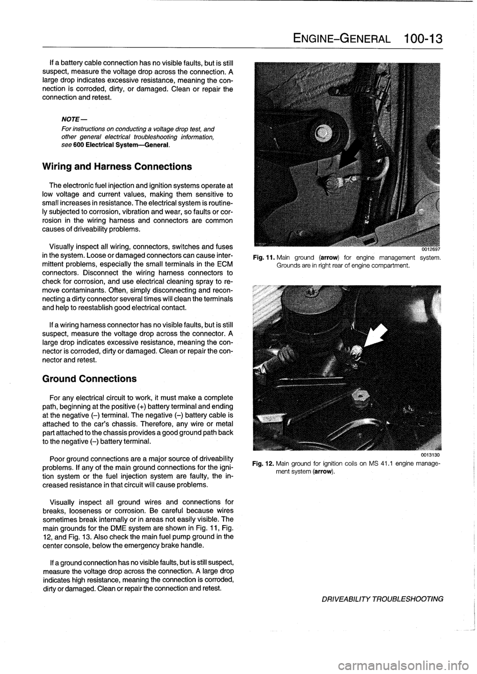
The
main
grounds
for
the
DME
system
are
shown
in
Fig
.
11,Fig
.
12,
and
Fig
.
13
.
Also
check
the
main
fuel
pump
ground
in
the
center
console,
below
the
emergency
brake
handle
.
If
a
ground
connection
has
no
visiblefaults,
but
is
still
suspect,
measure
the
voltage
drop
acrossthe
connection
.
A
large
drop
indicates
high
resistance,
meaning
the
connection
is
corroded,
dirty
or
damaged
.
Clean
or
repair
the
connection
and
retest
.
ENGINE-GENERAL
100-
1
3
UU,~uyi
Fig
.
11
.
Mainground
(arrow)
for
engine
management
system
.
Grounds
are
in
right
rear
of
engine
compartment
.
Fig
.
12
.
Mainground
for
ignition
coils
on
MS
41
.1
engine
manage-
ment
system
(arrow)
.
DRIVEABILITY
TROLIBLESHOOTING
Page 163 of 759
BOSCH
DME
MM
AND
M33
.1
COMPONENT
TESTS
AND
REPAIRS
Consult
Table
a
for
engine
application
information
for
the
Bosch
DME
3
.1
and
3
.3.1
systems
.
The
DME
3
.1
and
DME
3
.3
.1
systems
are
similar
in
opera-
tion,
with
knock
control
and
VANOS
operation
being
the
key
differences
.
DME
3
.1
engines
arenot
equipped
with
VANOS
or
knock
detectors,
while
the
DM
E3
.3
.1
system
is
.
CA
UTION-
Use
onty
a
digital
multimeter
when
testing
wiring
.
Use
of
an
analog
VOM
may
damage
the
engine
control
module
.
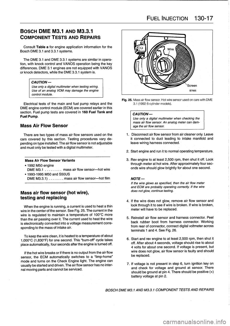
Fig
.
25
.
Mass
air
flow
sensor
.
Hot
wire
sensor
usedon
carswith
DME
Electrical
tests
of
the
main
and
fuel
pump
relays
and
the
3
.1
(1992
6-cylinder
models)
.
DME
engine
control
module
(ECM)
are
covered
earlier
in
this
section
.
Fuel
pump
tests
are
covered
in
160
Fuel
Tank
and
CAUTION-
Fuel
Pump
.
Use
only
a
digital
multimeter
when
checking
the
mass
air
flow
sensor
.
An
analog
meter
can
dam-
Mass
Air
Flow
Sensor
age
theair
flow
sensor
.
There
are
two
types
of
mass
air
flow
sensors
used
onthe
1
.
Disconnect
air
flow
sensor
from
air
cleaner
only
.
Leave
cars
covered
by
this
section
.
Testing
procedures
vary
de-
it
connected
to
duct
leading
to
intake
manifold
and
pending
on
type
installed
.
The
airflow
sensor
is
not
adjustable
leave
wiring
harness
connected
.
and
must
only
be
tested
with
a
digital
multimeter
.
Mass
Air
FlowSensor
Variants
"
1992
M50
engine
DME
M3
.1
.
.
.
.
...
..
mass
air
flow
sensor-hot
wire
"
1993-1995
M50
and
S50US
DMEM33
.1)
.
...
...
.
mass
air
flow
sensor-hot
film
Mass
air
flow
sensor
(hot
wire),
testing
and
replacing
When
the
engine
is
running,
a
current
is
used
to
heat
a
thin
wire
in
the
center
of
the
sensor
.
See
Fig
.
25
.
The
current
in
the
wire
is
regulated
to
maintain
a
temperature
of
100°C
more
than
the
air
passing
over
it
.
The
current
used
to
heat
the
wire
is
electronically
conneced
into
a
voltage
measurement
corre-
sponding
to
the
mass
of
intake
a¡
r
.
To
keep
the
wire
clean,
it
is
heated
to
a
temperature
of
about
1,000°C
(1,830°F)
for
one
second
.
This
"burn-off"
cycle
takes
place
automatically,
four
seconds
after
the
engine
is
tumed
off
.
lf
thehot
wire
breaks
or
if
there
is
no
output
from
the
air
flow
sensor,
the
ECM
automatically
switches
to
a
"limp-home"
mode
and
tucos
on
the
Check
Engine
light
.
The
engine
can
usually
be
started
and
driven
.
The
air
flow
sensor
has
no
inter-
nal
moving
parts
and
cannot
be
serviced
.
FUEL
INJECTION
130-
1
7
2
.
Start
engine
and
run
it
to
normal
operating
temperature
.
3
.
Rev
engine
toat
least
2,500
rpm,then
shut
it
off
.
Look
through
meter
at
hot
wire
.
After
approximately
four
sec-
onds
wire
should
glow
brightly
for
about
one
second
.
NOTE
-
If
the
wire
glowsas
specified,
then
the
airflow
meter
and
ECM
are
probably
operating
correctly
.
lf
the
wire
does
not
glow,
continue
testing
.
4
.
lf
the
wire
does
not
glow,
remove
air
flow
sensor
and
look
through
it
to
see
if
wire
is
broken
.
lf
wire
is
broken,
meter
will
have
to
be
replaced
.
5
.
Reinstall
air
flow
sensor
and
harness
connector
.
Peel
back
rubber
bootfrom
harness
connector
.
Working
from
rear
of
connector,
connect
digital
voltmeter
across
terminals
1
and
4
.
See
Fig
.
26
.
6
.
Start
and
rev
engine
toat
least
2,500
rpm,thenshut
it
off
.
After
about
4
seconds,
voltage
should
riseto
about
4
volts
for
about
one
second
.
lf
voltage
is
present,
but
wire
does
not
glow,
air
flow
sensor
is
faulty
and
should
be
replaced
.
7
.
lf
voltage
is
not
present
in
step
6,
turn
ignition
key
on
and
check
for
voltage
and
ground
at
sensor
.
There
should
beground
at
pin
4
.
There
should
be
positive
(+)
battery
voltage
at
pin
2
.
BOSCH
DME
M3
.1
AND
M32
.1
COMPONENT
TESTS
AND
REPAIRS
Page 164 of 759
130-18
FUEL
INJECTION
The
engine
coolant
temperature
(ECT)
sensor
sends
con-
tinuous
engine
coolant
temperature
information
to
the
ECM
.
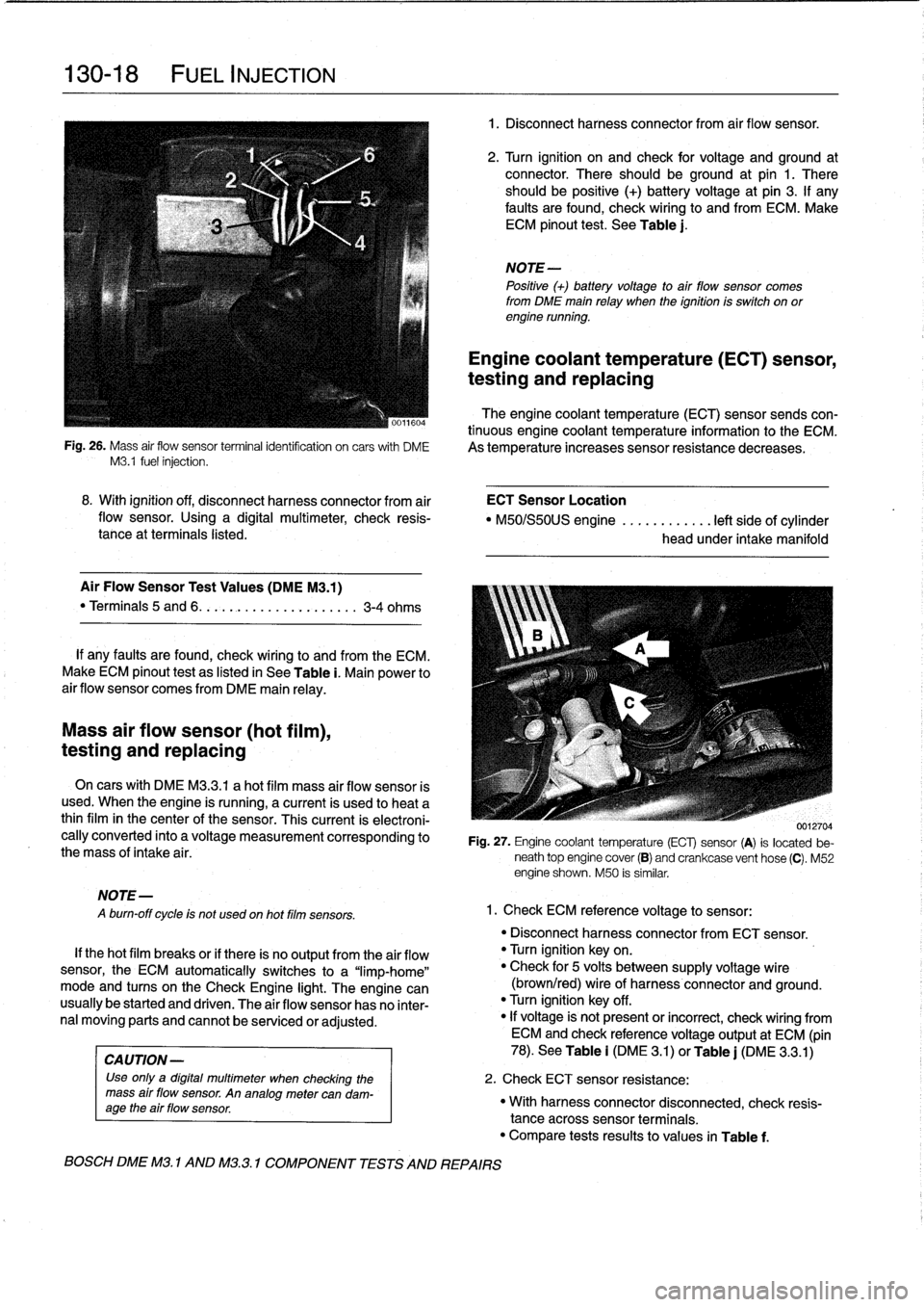
Fig
.
26
.
Mass
air
flow
sensor
terminalidentifcation
on
carswith
DME
As
temperature
increases
sensor
resistance
decreases
.
M3
.1
fuel
injection
.
Mass
air
flow
sensor
(hot
film),
testing
and
replacing
MOTE-
A
burn-off
cycle
is
not
used
on
hot
film
sensors
.
8
.
With
ignition
off,
disconnect
harness
connector
from
air
ECT
Sensor
Location
flow
sensor
.
Using
a
digital
multimeter,
check
resis-
"
M50/S50US
engine
............
left
side
of
cylinder
tance
at
terminals
listed
.
head
under
intake
manifold
Air
Flow
Sensor
Test
Values
(DMEM3
.1)
"
Terminals
5
and
6
.
.
.
.........
..
.
..
....
3-4
ohms
If
any
faults
are
found,
check
wiring
lo
and
from
the
ECM
.
Make
ECM
pinout
test
as
listed
in
See
Table
i
.
Main
power
to
air
flow
sensor
comes
from
DME
main
relay
.
On
cars
with
DME
M3
.3
.1
a
hot
film
mass
air
flow
sensor
is
used
.
When
the
engine
is
running,
a
current
is
used
lo
heat
a
thinfilm
in
the
center
of
the
sensor
.
This
current
is
electroni-
cally
converted
into
a
voltage
measurement
corresponding
to
the
mass
of
intake
air
.
If
thehot
film
breaks
or
if
there
is
no
output
from
the
air
flow
sensor,
the
ECM
automatically
switches
to
a
"limp-home"
mode
and
tucos
on
the
Check
Engine
light
.
The
engine
can
usually
be
started
and
driven
.
The
air
flow
sensor
has
no
inter-
nal
moving
parts
and
cannot
be
senricedor
adjusted
.
CA
UTION-
Use
only
a
digital
multimeter
when
checking
the
mass
air
flow
sensor
.
An
analogmetercan
dam-
age
the
air
flow
sensor
.
BOSCH
DME
M3
.
1
AND
M32
.1
COMPONENT
TESTS
AND
REPAIRS
1
.
Disconnect
harnessconnector
from
air
flow
sensor
.
2
.
Turn
ignition
on
and
check
for
voltage
and
ground
at
connector
.
There
should
beground
at
pin
1
.
There
should
be
positive
(+)
battery
voltage
at
pin
3
.
If
any
faults
are
found,
check
wiring
to
and
from
ECM
.
Make
ECM
pinout
test
.
See
Table
j
.
NOTE-
Positive
(+)
battery
voltage
to
air
flow
sensor
comes
from
DME
main
relay
when
the
ignition
is
switch
on
orengine
running
.
Engine
coolant
temperature
(ECT)
sensor,
testing
and
replacing
0012704
Fig
.
27
.
Engine
coolant
temperature
(ECT)
sensor
(A)
is
located
be-
neath
top
engine
cover
(B)
and
crankcase
vent
hose
(C)
.
M52
engine
shown
.
M50
is
similar
.
1
.
Check
ECM
reference
voltage
to
sensor
:
"
Disconnect
harnessconnector
from
ECT
sensor
.
"
Turn
ignition
keyon
.
"
Check
for
5
volts
between
supply
voltage
wire
(brown/red)
wire
of
harness
connector
and
ground
.
"
Turn
ignition
key
off
.
"
If
voltage
is'
not
present
or
incorrect,
check
wiring
from
ECM
and
check
referencevoltage
output
at
ECM
(pin
78)
.
See
Table
i
(DM
E
3
.1)
or
Table
j
(DME
3
.3
.1)
2
.
Check
ECT
sensor
resistance
:
"
With
harnessconnector
disconnected,
check
resis-
tance
acrosssensor
terminals
.
"
Compare
tests
results
to
values
in
Table
f
.
Page 383 of 759
NOTE
-
Sometimes
the
color
of
en
installed
wire
may
be
differ-
ent
than
the
one
on
the
wiring
diagram
.
Don't
be
con-
cerned
.
Just
be
sure
lo
confirm
that
the
wire
connects
lo
the
proper
terminals
.
Wire
color
codes
"
BLU
.........
.
..
..
...
.
.................
Blue
"
BRN
....:....
.
..
..
...
..
...............
Brown
"
YEL
.........
.
..
..
...................
.Yellow
"
GRN
.........
.
..
..
...
.
................
creen
"
G
RY
.......
.
.
.
..
..
.....................
G
ray
"
ORG
.........
.
..
..
...
.
..............
.Orange
"
RED
......
...
.
.
..
.....................
.Red
"
BLK
.........
.
..
..
...
.
................
Black
"
VIO
..........
.
..
...
..
..
.......
.
.......
Violet
"
WHT
.........
.
.
....
.
...
:..............
White
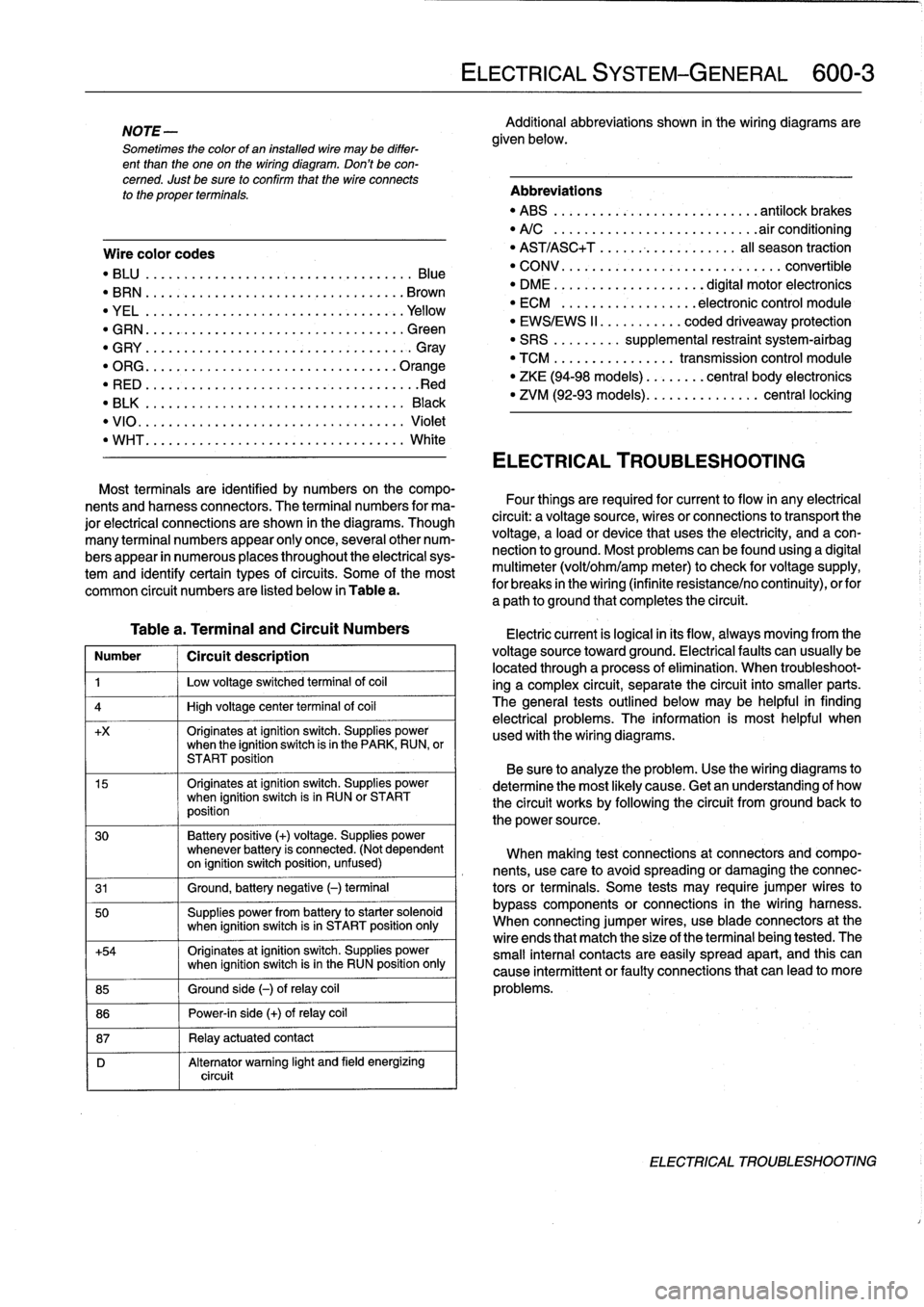
Table
a
.
Terminal
and
Circuit
Numbers
Number
1
Circuít
description
1
j
Low
voltage
switched
terminal
of
coi¡
4
1
High
voltage
center
termina¡
of
coi¡
+x
Originates
atignition
switch
.
Supplies
powerwhen
the
ignition
switch
is
in
the
PARK,
RUN,
or
START
position
15
Originates
atignition
switch
.
Supplies
powerwhen
ignition
switch
is
in
RUN
or
START
position
30
Battery
positive
(+)
voltage
.
Supplies
power
whenever
battery
is
connected
.
(Not
dependent
on
ignition
switch
position,
unfused)
31
1
Ground,
battery
negative
(-)
terminal
50
Supplies
power
from
battery
to
starter
solenoid
when
ignition
switch
isin
START
position
only
+54
Originates
atignition
switch
.
Supplies
power
when
ignition
switch
isin
the
RUN
position
only
85
1
Ground
side
(-)
ofrelay
coil
86
1
Power-in
side
(+)
ofrelay
coil
87
1
Relay
actuatedcontact
D
Alternator
warning
light
and
field
energizing
circuit
ELECTRICAL
SYSTEM-GENERAL
600-
3
Additional
abbreviations
shown
in
the
wiring
diagrams
are
given
below
.
Abbreviations
"
ABS
........
.
...
.
...
.
..........
antilock
brakes
"
A/C
........
.
...
..
..
.
.........
.airconditioning
"
AST/ASC+T
.......
...
.
.
.......
al¡
season
traction
"
CONV
.......
.
.
...
.................
convertible
"
DME
........
.
.
...
.......
digital
motor
electronics
"
ECM
.......
.
...
..
..
.
..
electronic
control
module
"
EWS/EWS
II
......
...
.
.
coded
driveaway
protection
"
SRS
........
.
supplemental
restraint
system-airbag
"
TCM
........
.
..
....
.
transmission
control
module
"
ZKE
(94-98
models)
..
..
.
...
central
body
electronics
"
ZVM
(92-93
models)
...
.
.
..
.
.......
central
locking
ELECTRICAL
TROUBLESHOOTING
Most
terminals
are
identified
by
numbers
on
the
compo-
nents
and
harness
connectors
.
The
terminal
numbers
for
ma-
Four
things
are
required
for
current
toflow
in
any
electrical
jor
electrical
connections
are
shown
in
the
diagrams
.
Though
circuit
:
a
voltagesource,
wires
or
connections
to
transport
the
many
terminal
numbers
appear
only
once,
severa¡other
num-
voltage,
a
load
or
device
that
uses
the
electricity,
and
a
con-
bers
appear
in
numerous
places
throughout
the
electrical
sys-
nection
to
ground
.
Most
problemscanbefound
using
a
digital
tem
and
identify
certain
types
ofcircuits
.
Some
of
the
most
multimeter
(volt/ohm/amp
meter)to
check
for
voltage
supply,
common
circuit
numbers
are
listed
below
in
Table
a
.
for
breaks
in
the
wiring
(infinite
resistance/no
continuity),
orfor
a
path
to
ground
that
completesthe
circuit
.
Electric
current
is
logical
in
its
flow,
always
moving
from
the
voltage
sourcetoward
ground
.
Electricalfaults
can
usually
be
located
through
a
process
of
elimination
.
When
troubleshoot-
ing
a
complex
circuit,
separate
the
circuit
into
smaller
parts
.
The
general
testsoutlined
below
may
be
helpful
in
finding
electrical
problems
.
The
information
is
most
helpful
when
used
with
the
wiring
diagrams
.
Be
sure
to
analyze
the
problem
.
Use
the
wiring
diagrams
to
determine
the
most
likely
cause
.
Getan
understanding
of
how
the
circuit
works
by
following
the
circuit
from
groundback
to
the
power
source
.
When
making
test
connections
at
connectors
andcompo-
nents,
use
care
to
avoidspreading
or
damaging
the
connec-
tors
or
terminals
.
Some
tests
may
require
jumper
wires
to
bypass
components
or
connections
in
the
wiring
harness
.
When
connecting
jumper
wires,
use
bladeconnectors
at
the
wire
ends
that
match
the
size
of
the
terminal
being
tested
.
The
small
interna¡
contacts
are
easily
spread
apart,
and
this
can
cause
intermittent
or
faultyconnections
that
can
leadto
more
problems
.
ELECTRICAL
TROUBLESHOOTING
Page 457 of 759
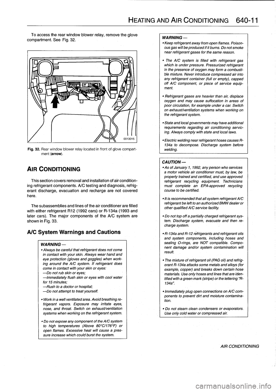
To
access
the
rear
window
blower
relay,
remove
the
glove
compariment
.
See
Fig
.
32
.
Fig
.
32
.
Rear
window
blower
relay
located
in
frontof
glove
compart-
ment
(arrow)
.
AIR
CONDITIONING
Thissection
covers
removal
and
installation
of
air
condition-
ing
refrigerant
components
.
A/C
testing
and
diagnosis,
refrig-
erantdischarge,
evacuatíon
and
recharge
are
not
covered
here
.
The
subassemblies
and
lines
of
the
air
conditionerare
filled
with
either
refrigerant
R12
(1992
cars)
or
R-134a
(1993
and
later
cars)
.
The
major
components
of
the
A/Csystem
are
shown
in
Fig
.
33
.
A/CSystem
Warnings
and
Cautions
WARNING
-
"
Always
be
careful
that
refrigerant
does
not
come
in
contact
with
your
skin
.
Always
wearhand
andeye
protection
(gloves
and
goggles)
when
work-
ing
around
the
AIC
system
.
If
refrigerant
does
come
in
contact
with
your
skin
oreyes
:
-Do
not
rub
skin
oreyes
;
-Immediately
flush
skin
oreyes
withcool
water
for
15
minutes
;
-Rush
to
a
doctor
orhospital
;
-Do
not
attempt
to
treat
yourself
.
"
Work
in
a
wefl
ventilated
area
.
Avoid
breathing
re-
frigerant
vapors
.
Exposure
may
irrítate
eyes,
nose,
and
throat
.
Switch
on
exhaustlventilation
systems
when
working
on
the
refrigerant
system
.
"
Do
not
expose
any
component
of
the
AIC
system
to
high
temperatures
(Above
80°Cl176°F)or
open
flames
.
Excessive
heat
will
cause
a
pres-
sureincrease
whichcould
burst
the
system
.
HEATING
AND
AIR
CONDITIONING
640-
1
1
0013015
WARNING
-
"
Keep
refrigerant
away
from
open
llames
.
Poison-
ous
gas
will
be
produced
if
it
bums
.
Do
not
smoke
near
refrigerant
gases
for
the
same
reason
.
"
The
AICsystem
is
filled
with
refrigerant
gas
which
is
under
pressure
.
Pressurized
refrigerant
in
the
presenceof
oxygen
may
forma
combusti-
ble
mixture
.
Never
introduce
compressed
air
finto
any
refrigerant
container
(full
or
empty),
capped
off
AIC
component,
or
piece
of
service
equip-
ment
.
"
Refrígerant
gases
are
heavier
than
air,
displace
oxygen
and
may
cause
suffocation
in
areas
of
poor
círculation,
for
example
under
a
car
.
Switch
on
exhaustlventilation
systems
when
working
on
the
refrigerant
system
.
"
State
and
local
governments
may
have
additional
requirements
regarding
air
conditioning
servic-
ing
.
Alwayscomply
with
state
and
local
laws
.
"
Electric
welding
near
refrigerant
hoses
causes
R-134a
to
decompose
.
Discharge
system
before
welding
.
CA
UTION
-
-As
of
January
1,
1992,
any
person
who
services
a
motor
vehicle
air
conditioner
must,
by
law,
be
properly
trained
and
certified,
and
use
approved
refrigerant
recycling
equipment
.
Technicians
must
complete
an
EPA-approved
recycling
course
to
be
certified
.
"
It
is
recommended
that
al¡
system
refrigerant
AIC
refrigerant
be
left
to
an
authorized
BMW
dealer
or
other
qualified
AIC
service
facility
.
"
Do
not
top
off
a
partially
charged
refrigerant
sys-
tem
.
Dischargesystem,evacuate
and
then
re-
charge
system
.
"
R-134a
and
R-12
refrigerants
and
refrigerant
oils
and
system
components,
including
hoses
and
sealing
O-rings,
are
NOT
compatible
.
Compo-
nent
damage
andlor
system
contamination
will
result
.
"
The
mixture
of
refrigerant
oil
(PAG
oil)
and
refrig-
erant
R-134a
attacks
some
metals
and
alloys
(for
example,copper)
and
breaks
down
certain
hose
materials
.
Use
only
hoses
and
lines
that
are
iden-
tified
with
a
green
mark
(stripe)
or
the
lettering
R-
134a"
.
"
Immediately
plug
open
connections
on
AIC
com-
ponents
to
prevent
dirt
and
moisture
contamina-
tion
.
"
Do
not
steam
clean
condensers
or
evaporators
.
Use
only
cold
water
or
compressed
air
.
AIR
CONDITIONING
Page 483 of 759
Front
side-impact
airbag,
removing
and
installing
1
.
Disconnect
negative
(-)
cable
from
battery
and
cover
negative
terminal
with
insulating
material
.
CA
UTION-
"
Store
the
removed
airbag
unit
with
the
soft
pad
Prior
to
disconnectiog
the
battery,
read
the
battery
facing
up
.
ff
stored
facíng
down,
accidental
de-
disconnection
cautions
given
at
the
front
of
this
ployment
could
propel
it
violently
into
the
air,
manual
on
page
viii
.
causing
injury
.
2
.
Remove
inside
door
panel
as
described
in
411
Doors
.
Remove
vapor
shield
.
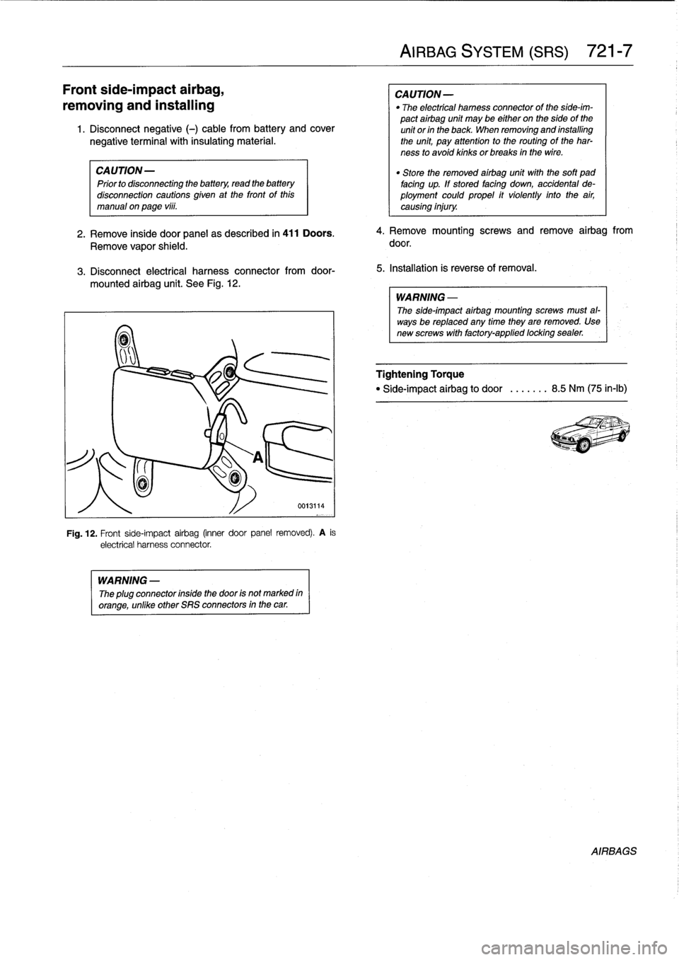
3
.
Disconnect
electrical
harness
connectorfrom
door-
mounted
airbag
unit
.
See
Fig
.
12
.
WARNING
-
The
plug
connector
insidethe
door
is
not
marked
in
orange,
unlike
other
SRS
connectors
in
the
car
.
Fig
.
12
.
Front
side-impact
airbag
(inner
door
panel
removed)
.
A
is
electrical
harness
connector
.
AIRBAG
SYSTEM
(SRS)
721-
7
CAUTION-
"
The
electrical
harness
connector
of
the
side-im-
pact
airbag
unit
may
be
either
on
the
sideof
the
unít
or
in
the
back
When
removing
and
installing
the
unit,
pay
attention
to
the
routing
of
the
har-
ness
to
avoid
kinks
orbreaks
in
the
wire
.
4
.
Remove
mounting
screws
andremove
airbag
from
door
.
5
.
Installation
is
reverse
of
removal
.
WARNING
-
The
side-impact
airbag
mounting
screws
must
al-
ways
be
replaced
any
time
they
are
removed
.
Usenew
screws
with
factory-applied
locking
sealer
.
Tightening
Torque
"
Side-impact
airbag
to
door
..
.....
8
.5
Nm
(75
in-lb)
AIRBAGS