vanos BMW 325i 1993 E36 Workshop Manual
[x] Cancel search | Manufacturer: BMW, Model Year: 1993, Model line: 325i, Model: BMW 325i 1993 E36Pages: 759
Page 43 of 759
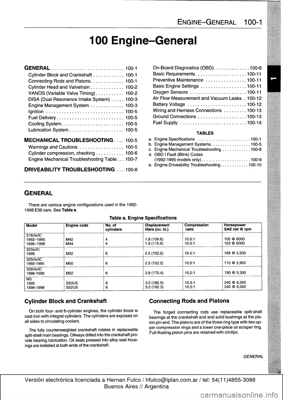
GENERAL
.
.....
.
.
.
.
.
.
.
...
.
.
.
.
.
.
.
.
.
...
100-1
Cylinder
Block
and
Crankshaft
.
.
.
.
.
.
.
.
.
...
100-1
Connecting
Rods
and
Pistons
.
.
.
.
.
.
.
.
.
.
.
.
.
100-1
Cylinder
Head
and
Valvetrain
.
.
.
.
.
.
.
.
.
.
.
.
.
100-2
VANOS
(Variable
Valve
Timing)
.
.
.
.
.
.
.
.
...
100-2
DISA
(Dual
Resonance
Intake
System)
.
.
.
.
.
100-3
Engine
Management
System
.
.
.
.
.
.
.
.
.
.
.
.
.
100-3
Ignition
......
.
.
.
.........
.
.
.
.
.
.
.
.
.
.
.
.
100-5
Fuel
Delivery
..
.
.
.
.....
.
...
.
.
.
.
.
.
.
.
.
.
.
.
100-5
Cooling
System
.
...........
.
.
.
.
.
.....
.
.
100-5
Lubrication
System
.........
.
.
.
.
.
.
.
.
.
.
.
.
100-5
MECHANICALTROUBLESHOOTING
.
.
.
.
100-5
Warnings
and
Cautions
..
.
...
.
.
.
.
.
.
.
.
.
.
.
.
100-5
Cylinder
compression,
checking
.
.
.
.
.
.
.
.
.
.
.
100-6
EngineMechanical
Troubleshooting
Table
.
.
.
100-7
DRIVEABILITY
TROUBLESHOOTING
...
100-8
GENERAL
There
are
various
engíne
configurations
used
in
the
1992-
1998
E36
cars
.
See
Table
a
.
On
both
four-
and
6-cylinder
engines,
the
cylinder
block
is
cast
¡ron
with
integral
cyiinders
.
The
cyiinders
are
exposed
on
all
sides
to
circulating
coolant
.
The
fully
counterweighted
crankshaft
rotates
in
replaceable
split-shell
main
bearings
.
Oiiways
drilled
into
the
crankshaft
pro-
vide
bearing
lubrication
.
O¡I
seals
pressed
into
alloy
sea¡
hous-
ings
are
installedat
both
ends
of
the
crankshaft
.
100
Engine-General
Tablea
.
Engine
Specifications
ENGINE-GENERAL
100-1
On-Board
Diagnostics
(OBD)
...
.
.
.
.
.
.
.
.
.
.
.
100-8
Basic
Requirements
....
.
.
.
...
.
.
.
.
.
....
.100-11
Preventive
Maintenance
......
.
.
.
.
.
.....
100-11
Basic
Engine
Settings
..
.
.....
.
.
.
.
.
.....
100-11
Oxygen
Sensors
.
.
.
...
.
.
.
...
.
.
.
.
.
....
.100-11
Air
Flow
Measurement
and
Vacuum
Leaks
.
.100-12
Battery
Voltage
.
.
...........
.
.
.
.
.
.....
100-12
Wiring
and
Harness
Connections
.
.
.
.
.....
100-13
Ground
Connections
...
.
.....
.
.
.
.
.
.....
100-13
Fue¡
Supply
....
.
...........
.
.
..
.....
.100-14
TABLES
a
.
Engine
Specifications
...
...
...........
.
..
..
.100-1
b
.
Engine
Management
Systems
..
..
...........
..
100-5
c
.
Engine
Mechanical
Troubleshooting
..........
.
.
100-8
d
.
OBD
1
Fault
(Blink)
Codes
(1992-1995
models
only)
.
...
..
..
..........
..
.100-9
e
.
Engine
Driveability
Troubleshooting
...........
.100-15
Model
Engine
code
No
.
of
Dispiacement
Compression
Horsepower
cyiinders
liters
(cu
.
in
.)
ratio
SAE
net
@
rpm
318i/is/¡C
1992-1995
M42
4
1
.8
(109
.6)
10
.0
:1
100
@
6000
1996-1998
M44
4
1
.9
(115
.6)
~
10
.0
:1
103
@
6000
323ís/iC
1998
M52
6
2
.5
(152
.2)
10
.5
:1
168
@
5,500
325i/is/iC
1992-1995
M50
6
2
.5
(152
.2)
10
.0
:1
110
@
5,900
328i/is/iC
1996-1998
M52
6
2
.8
(170
.4)
10
.2
:1
190
@
5,300
M3
1995
S50US
6
3
.0
(182
.5)
10
.5:1
240
@
6,000
1996-1998
S52US
6
3
.2
(192
.3)
10
.5:1
240
@
6,000
Cylinder
Block
and
Crankshaft
Connecting
Rods
and
Pistons
The
forged
connecting
rods
use
replaceable
split-shell
bearings
at
the
crankshaft
endand
solid
bushings
at
the
pis-
ton
pin
end
.
The
pistonsare
of
the
three-ring
typewith
two
up-
per
compression
rings
and
a
lowerone-piece
o¡i
scraper
ring
.
Fui¡-floating
piston
pins
are
retained
with
circlips
.
GENERAL
Page 44 of 759
100-2
ENGINE-GENERAL
Cylinder
Head
and
Valvetrain
The
aluminum
cylinder
head
uses
chain-driven
double
overhead
camshafts
and
four
valves
per
cylinder
.
See
Fig
.
1
.
The
cylinder
head
employs
a
crossflow
design
for
greater
power
and
efficiency
.
Intake
air
enters
the
combustion
cham-
ber
from
one
side
while
exhaust
gasses
exit
from
the
other
.
Oílways
in
the
head
provide
lubrication
for
the
camshafts)
and
valvetrain
.
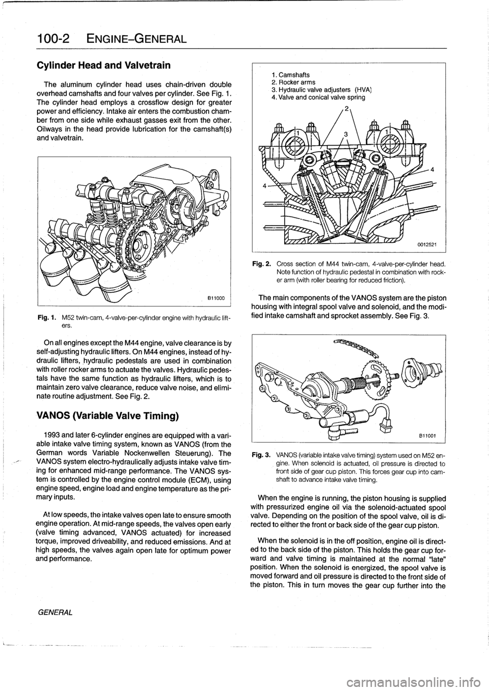
Fig
.
1
.
M52
twin-cam,
4-valve-per-cylinder
engine
with
hydraulíc
lift-
ers
.
On
all
engines
exceptthe
M44
engine,
valveclearance
is
by
seif-adjusting
hydraulic
lifters
.
On
M44
engines,
instead
of
hy-
draulic
lifters,
hydraulic
pedestaisare
used
in
combination
with
roller
rocker
arms
to
actuate
the
valves
.
Hydraulic
pedes-
tals
have
the
same
function
as
hydraulic
lifters,
which
ís
to
maintain
zero
valve
clearance,
reduce
valve
noise,
and
elimí-
nate
routíne
adjustment
.
See
Fig
.
2
.
VANOS
(Variable
Valve
Timing)
GENERAL
1
.
Camshafts
2
.
Rocker
arms
3
.
Hydraulic
valve
adjusters
(HVA)
4
.
Valve
and
conical
valve
spring
4
Fig
.
2
.
Cross
sectionof
M44
twin-cam,
4-valve-per-cylinder
head
.
Note
function
of
hydraulíc
pedestal
in
combination
with
rock-er
arm
(with
roller
bearing
for
reduced
friction)
.
The
main
components
of
the
VANOS
system
arethe
piston
housing
with
integral
spool
valve
and
solenoid,
and
the
modi-
fied
intake
camshaft
and
sprocket
assembly
.
See
Fig
.
3
.
1993
and
later
6-cylinder
engines
are
equipped
with
a
vari-
B11001
able
intake
valve
timing
system,
known
as
VANOS
(from
the
German
words
Variable
Nockenwellen
Steuerung)
.
The
Fig
.
3
.
VANOS
(variable
intake
valve
timing)
systemusedon
M52
en-
VANOS
system
electro-hydraulically
adjusts
intake
valve
tim-
gine
.
When
solenoid
is
actuated,
oíl
pressure
is
directed
to
ingfor
enhanced
mid-range
performance
.
The
VANOS
sys-
front
side
of
gear
cup
piston
.
This
forces
gear
cup
finto
camtem
is
controlled
by
the
engine
control
module
(ECM),
using
shaft
to
advance
intake
valve
timing
.
enginespeed,engine
load
and
engine
temperature
asthe
pri-
mary
inputs
.
When
the
engine
is
running,
the
piston
housing
is
supplied
with
pressurized
engine
oil
víathe
solenoid-actuatedspool
At
low
speeds,
the
intake
valves
open
late
to
ensure
smooth
valve
.
Depending
on
the
position
of
the
spool
valve,
oil
isdi
engine
operation
.
At
mid-rangespeeds,
thevalves
open
early
rected
to
either
the
front
or
back
side
of
the
gear
cup
piston
.
(valvetiming
advanced,
VANOS
actuated)
for
increased
torque,
improved
driveability,
and
reduced
emissions
.
And
at
When
the
solenoid
isin
the
off
position,
engine
oíl
is
direct-
high
speeds,
the
valves
again
open
late
for
optimum
power
ed
to
the
back
side
of
the
piston
.
This
holds
the
gear
cup
for-
and
performance
.
ward
and
valve
timing
is
maintained
at
the
normal
"late"
position
.
When
the
solenoid
is
energized,
the
spoolvalve
is
moved
forward
and
oil
pressure
is
directed
to
the
front
side
of
the
piston
.
This
in
turn
moves
thegear
cup
further
into
the
Page 45 of 759
camshaft
secondary
drive,
causing
thecamshaft
to
"advance"
12
.5°
.
The
helical
gears
are
cut
so
that
forward
motion
of
the
gear
cup
is
transiated
into
rotational
motion
of
the
camshaft
.
See
117
Camshaft
Timing
Chain
for
testing
and
repair
infor-
mation
on
the
VANOS
system
.
DISA
(Dual
Resonance
Intake
System)
DISA,usedon
4-cylinder
engines,
is
a
dual
intake
runner
system
that
effectively
provides
the
advantages
of
both
short
and
long
intake
runners
within
the
same
engine
.
For
best
per-
formance,
long
intake
runners
aremost
beneficial
atlow-
and
mid-engine
speeds
(below
4,200
rpm),
and
short
intake
run-
ners
enhance
torque
at
high
engine
speeds
(above4,200
rpm)
.
NOTE-
The
term
DISA
comes
from
the
German
words
Differ-
enzierte
Sauganlage,
and
can
roughty
be
transiated
as
a
differing
intake
manifold
configuration
.
The
DISA
solenoid
valve
is
controlled
by
the
DME
control
module,
using
engine
speed
as
the
primary
input
.
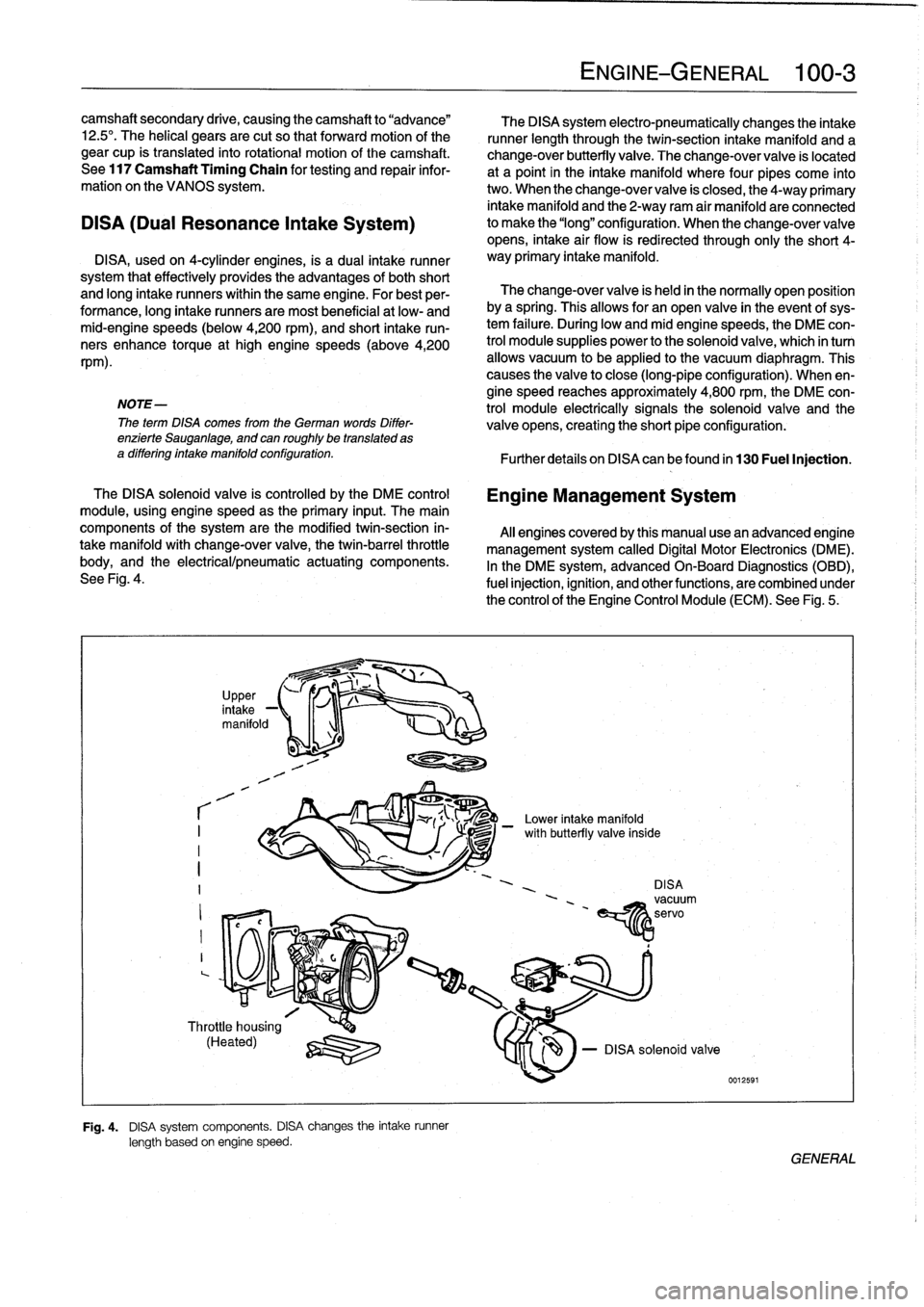
The
main
components
of
the
system
are
the
modified
twin-section
in-
takemanifoldwith
change-over
valve,
the
twin-barrel
throttle
body,
and
the
electrical/pneumatic
actuating
components
.
See
Fig
.
4
.
r
I
I
I
?
,
in
UpPer,
take
-1
manifold
1
-1
Throttle
housing
(Heated)
q
:lZU
Fig
.
4
.
DISA
system
components
.
DISA
changes
the
intake
runner
length
based
on
engine
speed
.
The
DISA
system
electro-pneumatically
changes
the
intake
runner
length
through
the
twin-section
intake
manifold
and
a
change-over
butterfly
valve
.
The
change-over
valve
is
located
at
a
point
in
the
intake
manifold
where
four
pipes
come
into
two
.
When
the
change-over
valve
is
closed,
the
4-way
primary
intake
manifold
and
the
2-way
ram
air
manifold
areconnected
to
make
the
"long"
configuration
.
When
the
change-overvalve
opens,
intake
air
flow
is
redirected
through
only
the
short
4-
way
primary
intake
manifold
.
The
change-over
valve
is
held
in
the
normally
open
position
bya
spring
.
Thisallows
for
an
open
valve
in
the
event
of
sys-
tem
failure
.
During
low
andmid
enginespeeds,
the
DME
con-
trol
module
supplies
power
to
the
solenoid
valve,
which
in
turn
allows
vacuum
to
be
applied
lo
the
vacuum
diaphragm
.
This
causes
the
valve
to
close
(long-pipe
configuration)
.
When
en-
gine
speed
reaches
approximately
4,800
rpm,
the
DME
con-
trol
module
electrically
signals
the
solenoid
valve
and
the
valve
opens,
creating
the
short
pipe
configuration
:
Further
detafs
on
DISA
canbefound
in
130
Fuel
Injection
.
Engine
Management
System
Al¡
enginescoveredby
this
manual
usean
advanced
engine
management
system
called
Digital
Motor
Electronics
(DME)
.
In
the
DME
system,
advancedOn-Board
Diagnostics
(OBD),
fuel
injection,
ignition,
and
otherfunctions,
are
combined
under
the
control
of
theEngine
Control
Module
(ECM)
.
See
Fig
.
5
.
-
Lower
intake
manifold
DISAvacuum
'
~servo
EíY1z
ENGINE-GENERAL
100-
3
le
-
DISA
solenoid
valve
0012591
/
with
butterfly
va¡
GENERAL
Page 47 of 759
ignition
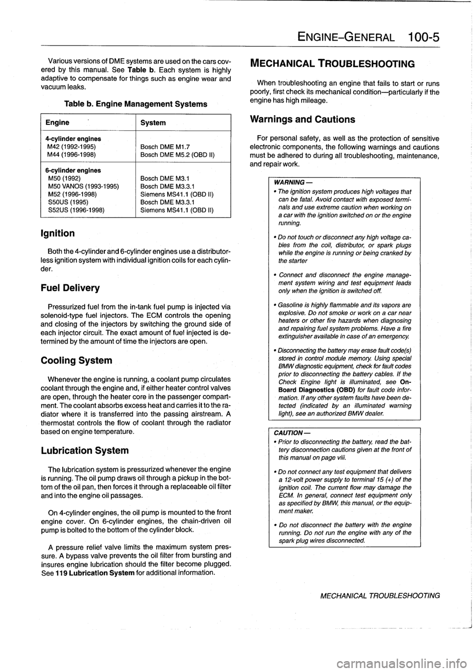
Table
b
.
Engine
Management
Systems
engine
has
high
mileage
.
Engine
1
System
4-cylinder
engines
M42
(1992-1995)
Bosch
DME
Ml
.7
M44
(1996-1998)
Bosch
DME
M5
.2
(OBD
II)
6-cylinder
engines
M50
(1992)
Bosch
DME
M3
.1
M50
VANOS
(1993-1995)
Bosch
DME
M3
.3
.1
M52
(1996-1998)
Siemens
MS41
.1
(OBD
II)
S50US
(1995)
Bosch
DME
M3
.3
.1
S52US
(1996-1998)
Siemens
MS41
.1
(OBD
II)
Both
the
4-cylinder
and
6-cylinder
engines
use
a
distributor-
less
ignition
system
with
individual
ignition
coils
for
each
cylin-
der
.
FuelDelivery
Pressurized
fuel
from
the
in-tank
fuel
pump
is
injected
via
solenoid-type
fuel
injectors
.
The
ECM
controls
the
opening
and
closing
of
the
injectors
by
switchingthe
ground
side
of
each
injector
circuit
.
The
exact
amount
of
fuel
injected
is
de-
termined
by
the
amount
of
timethe
injectors
are
open
.
Cooling
System
Whenever
the
engine
is
running,
acoolant
pump
circulates
coolant
through
the
engine
and,
if
either
heater
control
valves
are
open,
through
the
heater
core
in
the
passenger
compart-
ment
.
The
coolant
absorbs
excess
heat
and
carries
it
to
the
ra-
diator
where
it
is
transferred
into
the
passing
airstream
.
A
thermostat
controls
the
flow
of
coolant
through
the
radiator
based
on
engine
temperature
.
Lubrication
System
The
lubrication
system
is
pressurized
whenever
theengine
is
running
.
The
oil
pump
draws
oil
through
a
pickup
in
the
bot-
tom
of
the
oil
pan,thenforces
it
through
a
replaceable
oil
filter
and
finto
the
engine
oíi
passages
.
On
4-cylinder
engines,
the
oil
pump
is
mounted
to
the
front
engine
cover
.
On
6-cylinder
engines,thechain-driven
oil
pump
is
bolted
to
the
bottom
of
the
cylinder
block
.
A
pressure
relief
valve
limits
the
maximum
system
pres-
sure
.
A
bypass
valve
prevents
the
oil
filter
from
bursting
and
insures
engine
lubrication
should
the
filter
become
plugged
.
See
119
Lubrication
System
for
additional
information
.
ENGINE-GENERAL
100-
5
Various
versions
of
DME
systems
are
usedon
thecars
cov-
MECHANICAL
TROUBLESHOOTING
ered
by
this
manual
.
See
Table
b
.
Each
system
is
highly
adaptive
to
compensate
for
things
suchasengine
wear
and
When
troubleshooting
an
engine
that
fails
to
start
or
runs
vacuum
leaks
.
poorly,
first
check
its
mechanical
condition-particularly
if
the
Warnings
and
Cautions
For
personal
safety,
as
well
asthe
protection
of
sensitive
electronic
components,
the
following
warnings
and
cautions
must
be
adhered
to
during
all
troubleshooting,
maintenance,
and
repairwork
.
WARNING
-
"
The
ignition
system
produces
high
voltages
that
can
be
fatal
.
Avoid
contact
with
exposed
termi-
nals
anduse
extreme
caution
when
working
on
a
car
with
the
ignition
switched
on
or
the
engine
running
.
"
Do
not
touch
or
disconnect
any
high
voltage
ca-
bles
from
the
coil,
distributor,
orspark
plugs
while
the
engine
is
running
or
being
cranked
by
the
starter
"
Connect
and
disconnect
the
engine
manage-
ment
system
wiring
and
test
equipment
leads
only
when
the
ignition
is
switched
off
.
"
Gasoline
is
highly
flammable
and
its
vapors
are
explosive
.
Do
not
smoke
or
work
on
a
car
near
heaters
or
other
fire
hazards
when
diagnosing
and
repairing
fuel
system
problems
.
Have
a
fire
extínguisher
available
in
case
of
an
emergency
.
"
Disconnecting
the
battery
may
erase
fault
code(s)
stored
in
control
module
memory
.
Using
special
BMW
diagnosnnc
equipment,
check
for
fault
codes
prior
to
disconnecting
the
battery
cables
.
If
the
Check
Engine
lightis
illuminated,
see
On-
Board
Diagnostics
(OBD)
forfault
code
infor-
mation
.
If
any
other
system
faults
havebeen
de-tected
(indicated
byan
illuminated
warning
light),
see
an
authorized
BMW
dealer
.
CAUTION-
"
Prior
to
disconnecting
the
battery,
read
the
bat-
tery
disconnection
cautions
gíven
at
the
front
of
this
manual
on
page
viii
.
"
Do
notconnect
any
test
equipment
that
delivers
a
12-volt
power
supply
to
terminal15
(+)
of
the
ignition
coil
.
The
current
flow
may
damage
the
ECM
.
In
general,
connect
test
equipment
only
as
specified
by
BMW,
this
manual,
or
the
equip-
ment
maker
.
"
Do
not
disconnect
the
battery
with
the
engine
running
.
Do
notrunthe
engine
with
any
of
the
sparkplug
wires
disconnected
.
MECHANICAL
TROUBLESHOOTING
Page 52 of 759
100-
1
0
ENGINE-GENERAL
Table
d
.
OBD
I
Fault
(Blink)
Codes
(continued)
(1992-1995
modeis
only)
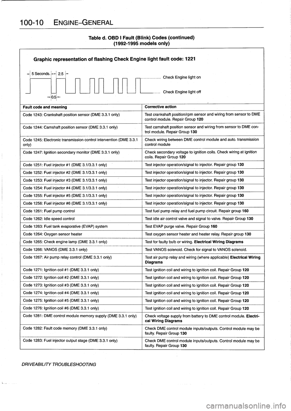
Graphic
representation
of
flashing
Check
Engine
light
fault
code
:
1221
-
;
5
Seconds
.
;--~
2
.5
r
----------------
Check
Engine
light
on
Fault
code
and
meaning
Corrective
action
Check
Engine
light
off
Code
1243
:
Crankshaft
position
sensor
(DME
3
.3
.1
only)
Test
crankshaft
position/rpm
sensor
and
wiring
from
sensor
lo
DME
control
module
.
Repair
Group
120
Code
1244
:
Camshaft
position
sensor
(DME
3
.3
.1
only)
Test
camshaft
position
sensor
and
wiring
fromsensor
to
DME
con-
trol
module
.
Repair
Group
130
Code
1245
:
Electronic
transmission
control
intervention
(DME
3
.3
.1
Check
wiring
between
DME
control
module
and
auto
.
transmission
only)
control
module
Code
1247
:
Ignition
secondary
monitor
(DME
3
.3
.1
only)
Check
secondary
voltage
lo
ignition
coils
.
Check
wiringat
ignition
coils
.
Repair
Group
120
Code
1251
:
Fuel
injector
#1
(DME
3
.113
.3
.1
only)
1
Test
injector
operation/signal
lo
injector
.
Repair
group130
Code
1252
:
Fuel
injector
#2
(DME
3
.113
.3
.1
only)
Test
injector
operation/signal
lo
injector
.
Repair
group130
Code
1253
:
Fuel
injector
#3
(DME
3
.1/3
.3
.1
only)
Test
injector
operation/signal
to
injector
.
Repair
group130
Code
1254
:
Fuel
injector
#4
(DME
3
.1/3
.3
.1
only)
Test
injector
operation/signal
to
injector
.
Repair
group
130
Code
1255
:
Fuel
injector
#5
(DME
3
.1/3
.3
.1
only)
Test
injector
operation/signal
to
injector
.
Repair
group130
Code
1256
:
Fuel
injector
#6
(DME
3
.1/3
.3
.1
only)
Test
injector
operation/signal
lo
injector
.
Repair
group130
Code
1261
:
Fuel
pump
control
Test
fuel
pump
relay
and
fuel
pump
circuit
.
Repairgroup
160
Code
1262
:
Idle
speed
control
Test
idleair
controlvalve
and
signalto
valve
.
Repair
Group
130
Code
1263
:
Fuel
tank
evaporative
(EVAP)
system
Test
EVAP
purge
valve
.
Repair
Group
160
Code
1264
:
Oxygen
sensor
heater
1
Test
oxygen
sensorheater
and
heater
relay
.
Repair
group
130
Code
1265
:
Check
engine
lamp
(DME
3
.3.1
only)
1
Test
for
faulty
bulb
or
wiring
.
Electrical
Wiring
Diagrams
Code
1266
:
VANOS
(DME
3
.3
.1
only)
1
Test
VANOS
solenoid
.
Check
for
signal
to
VANOS
solenoid
.
Code
1267
:
Air
pump
relay
control
(DME
3
.3
.1
only)
Test
air
pump
relay
and
wiring
(where
applicable)
Electrical
Wiring
Diagrams
Code
1271
:
Ignition
coil
#1
(DME
3
.3.1
only)
Test
ignitioncoil
and
wiring
toignitioncoil
.
Repair
Group
120
Code
1272
:
Ignition
coil
#2
(DME
3
.3.1
only)
Test
ignitioncoil
and
wiring
loignitioncoil
.
Repair
Group
120
Code
1273
:
Ignition
coil
#3
(DME
3
.3.1
only)
Test
ignitioncoil
and
wiring
loignitioncoil
.
Repair
Group
120
Code
1274
:
Ignítion
coil
#4
(DME
3
.3.1
only)
Test
ignitioncoil
and
wiring
toignitioncoil
.
Repair
Group
120
Code
1275
:
Ignitioncoil
#5
(DME
3
.3.1
only)
Test
ignition
coil
and
wiring
loignitioncoil
.
Repair
Group
120
Code
1276
:
Ignition
coil
#6
(DME
3
.3.1
only)
Test
ignitioncoil
and
wiring
loignitioncoil
.
Repair
Group
120
Code
1281
:
DME
control
module
memory
supply
(DME
3
.3
.1
only)
Check
voltage
supply
from
battery
lo
DME
control
module
.
Electri-
Code
1282
:
Fault
code
memory
(DME
3
.3.1
only)
Check
DME
control
module
inputs/outputs
.
Control
module
may
be
faulty
.
Repair
Group
130
Code
1283
:
Fuel
injector
output
stage
(DME
3
.3
.1
only)
Check
DME
control
module
inputs/outputs
.
Control
module
may
be
faulty
.
Repair
Group
130
DRIVEABILITY
TROUBLESHOOTING
cal
Wiring
Diagrams
Page 78 of 759
113-12
CYLINDER
HEAD
REMOVAL
AND
INSTALLATION
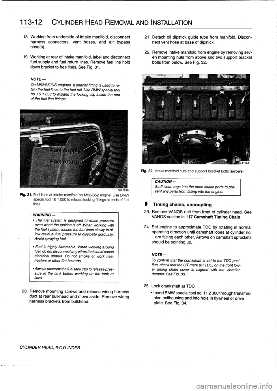
18
.
Working
from
underside
of
intake
manifold,
disconnect
21
.
Detach
oil
dipstick
guide
tube
from
manifold
.
Disconharness
connectors,
vent
hoses,
and
air
bypass
nectvent
hose
at
base
of
dipstick
.
hoses)
.
22
.
Remove
intake
manifold
from
engine
byremoving
sev-19
.
Working
at
rear
of
intake
manifold,
label
and
disconnect
en
mounting
nuts
from
above
andtwo
support
bracket
fuel
supply
and
fuel
return
lines
.
Remove
fuelline
hold
bolts
from
below
.
See
Fig
.
32
.
down
bracket
to
free
lines
.
See
Fig
.
31
.
NOTE-
On
M52IS52US
engines,
a
special
fitting
is
used
to
re-tain
the
fuel
fines
to
the
fuel
rail
.
Use
BMW
special
tool
no
.
16
1
050
to
expand
the
locking
clip
inside
the
end
of
the
fuellíne
fittings
.
WARNING
-
"
The
fuel
system
is
desígned
to
retan
pressure
even
wheh
the
ignition
is
off
.
When
working
with
the
fuel
system,
loosen
the
fuel
lines
slowly
toal-
low
residual
fuel
pressure
to
dissipate
gradually
.
Avoid
spraying
fuel
.
"
Fuel
is
highly
flammable
.
When
working
around
fuel,
do
not
disconnect
any
wires
that
could
cause
electrfcal
sparks
.
Do
not
smoke
orwork
near
heaters
or
other
fire
hazards
.
"
Always
unscrew
the
fuel
tank
cap
to
release
pres-
sure
in
the
tank
before
working
on
the
tank
or
lines
.
20
.
Remove
mountingscrews
and
release
wiring
harness
duct
at
rear
bulkhead
and
move
aside
.
Remove
wiring
harness
brackets
frombulkhead
.
CYLINDER
HEAD,
6-CYLINDER
Fig
.
32
.
Intake
manifoldnuts
and
support
bracket
bolts
(arrows)
.
CAUTION-
Stuff
clean
rags
into
the
open
intake
ports
topre-
001269s
vent
any
ports
from
falfing
into
the
engine
.
Fig
.
31
.
Fuel
lines
at
intake
manifold
on
M52/S52
engine
.
Use
BMW
special
tool
16
1
050
to
release
locking
fittings
at
ends
of
fuel
enes
.
1
Timing
chains,
uncoupling
23
.
Remove
VANOS
unit
from
frontof
cylinder
head
.
See
VANOS
section
in
117
Camshaft
Timing
Chain
.
24
.
Setengine
to
approximate
TDC
by
rotating
in
normal
operating
direction
until
camshaft
lobes
at
cylinder
no
.
1
are
facing
each
other
.
Arrows
on
camshaft
sprockets
should
be
pointing
up
.
NOTE-
To
confirm
that
the
crankshaft
is
set
to
the
TDC
posi-
tion,
check
that
the
OIT
mark
(0°
TDC)on
the
front
low-
er
timing
chain
cover
ís
aligned
with
the
víbration
damperSee
Fig
.
33
.
25
.
Lock
crankshaft
at
TDC
.
"
Insert
BMW
special
tool
no
.
11
2
300
through
transmis-
sion
bellhousing
and
finto
hole
in
flywheelor
drive
plate
.
See
Fig
.
34
.
Page 83 of 759
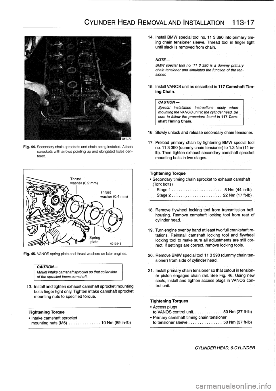
Fig
.
44
.
Secondary
chain
sprockets
and
chain
being
installed
.
Attachsprockets
with
arrows
pointing
upand
elongated
holes
cen-
tered
.
CYLINDER
HEAD
REMOVAL
AND
INSTALLATION
113-17
Spring
17
plate
0012543
Fig
.
45
.
VANOS
spring
plate
and
thrust
washerson
later
engines
.
14
.
Insta¡¡
BMW
special
tool
no
.
11
3
390
into
primary
tim-
ing
chain
tensioner
sleeve
.
Thread
tool
in
finger
tight
until
siack
is
removed
from
chain
.
NOTE-
BMW
special
tool
no
.
11
3
390
is
a
dummy
primary
chain
tensioner
and
simulatesthe
function
of
the
ten-
sioner
.
15
.
Insta¡¡
VANOS
unit
as
described
in
117
Camshaft
Tim-
ing
Chain
.
CAUTION-
Special
ínstallation
instructions
apply
when
mounting
the
VANOS
unit
to
the
cylinder
head
.
Be
sure
to
follow
the
procedurefound
in
117
Cam-
shaft
Timing
Chain
.
16
.
Slowlyuniock
and
release
secondary
chain
tensioner
.
17
.
Preloadprimary
chain
by
tightening
BMW
special
tool
no
.
11
3390
(dummy
chain
tensioner)
to
1.3
Nm
(11
in-
lb)
.
Then
tighten
exhaust
secondary
camshaft
sprocket
mounting
bolts
in
two
stages
.
Tightening
Torque
"
Secondary
timing
chain
sprocket
to
exhaust
camshaft
(Torx
bolts)
Stage
1
.
.............
..
..
.
...
5
Nm
(44
in-lb)
Stage
2
..............
..
..
.
,
.
..
22
Nm
(17
ft-1b)
18
.
Remove
flywheel
locking
tool
from
transmission
bell-
housing
.
Remove
camshaft
locking
tool
from
rear
of
cylinder
head
.
19
.
Turn
engine
over
by
hand
at
least
two
fui¡
crankshaft
ro-
tations
.
Reinstall
camshaft
locking
tool
and
flywheel
locking
toolto
make
sure
al¡
adjustments
are
still
cor-
rect
.
lf
settings
are
correct,
remove
locking
tools
.
20
.
Remove
BMW
special
tool
11
3390
(dummy
chain
ten-
sioner)
from
side
of
cylinder
head
.
CAUTION-
Mountintake
camshaft
sprocket
so
thatcollar
side
21
.
Insta¡¡
primary
chain
tensioner
so
that
cutout
in
tension-
of
the
sprocket
faces
camshaft
.
er
piston
engages
chain
rail
.
See
Fig
.
46
.
Using'new
seals,
install
and
tighten
access
plugs
in
VANOS
con
13
.
Install
and
tighten
exhaust
camshaft
sprocket
mounting
trol
unit
.
boits
finger
tight
only
.
Tighten
intake
camshaft
sprocket
mounting
nuts
to
specified
torque
.
Tightening
Torques
"
Access
plugs
Tightening
Torque
to
VANOS
control
unit
.
..
.
.
........
50
Nm
(37
ft-Ib)
"
Intake
camshaft
sprocket
"
Primary
camshaft
timing
chain
tensioner
mounting
nuts
(M6)
..............
10
Nm
(89
in-lb)
to
tensioner
sleeve
..
...
.
.
........
50
Nm
(37
ft-Ib)
CYLINDER
HEAD,
6-CYLINDER
Page 85 of 759
GENERAL
CYLINDER
HEAD,
DISASSEMBLY
AND
ASSEMBLY
CYLINDER
HEAD
AND
VALVETRAIN
116-1
116
Cylinder
Head
and
Valvetrai
n
GENERAL
.
.....
.
.
.
...
.
.
.
.
.
.
.
.
.
.......
116-1
Hydraulic
cam
followers,
checking
and
replacing
(M42
and
al¡
6-cylinder
engines)
.
...
.....
.
..
116-9
CYLINDER
HEAD,
Valve
guides
.
.
.
...
.
.
.
.
.
.
...
.
.
.
.
.
.
.
.
.
.
116-10
DISASSEMBLY
AND
ASSEMBLY
...
.
...
116-1
Valves
.
.
.
.
.
.
.
.
.
.
.
.
.
...
.
...
.
.
.
.
.
...
.
.
116-11
Camshafts,
removing
and
installing
(M42
engine)
....
.
....
.
.
.
.
.
.
.
.
.
.....
.
.
116-1
Valves,
leak
test
.
.
.
.
.
.
.
.
.
.
...
.
.
.
.
.
.
.
.
.
.
116-11
Camshafts,
removing
and
installing
Valve
stem
oil
seals
.
.
.
.......
.
.
.
.
.
...
.
.
116-11
(M44
engine)
.........
.
.
.
.
.
.
.
.
.
.......
116-3
Valve
seats
.
.
.
.
.
.
.
.
.
...
.
...
.
.
.
.
.
...
.
.116-12
Camshafts,
removing
and
installing
Valve
springs
.
.
.
.
.
.
.
.
...
.
...
.
.
.
.
.
.....
116-12
(6-cylinder
engine)
.....
.
.
.
.
.
.
.
.
.
.......
116-4
Valves,
removing
and
installing
........
.
....
116-6
TABLES
CYLINDER
HEAD
AND
VALVETRAIN,
a
.
Cylinder
Head
Height
........
....
.
..
..........
116-7
RECONDITIONING
.
...
.
.
.
.
.
.
.
.
.
.......
116-7
b
.
Camshaft
Specifications
.......
..
.
..
........
.116-7
Cylinder
head
...
.
.
.
...
.
.
.
.
.
.
.
.
.
....
.
..
116-7
c
.
Valve
Guide
Specifications
....
...
.
..
........
116-10
d
.
Valve
Specifications
...........
..
.
..
........
116-11
Camshaft
.
.
.
.
.
.
.
.
.
.
.
.
.
.
...
.
.
.
.
.
.......
116-7
e
.
Valve
Seat
Dimensions
.........
.
..
..
......
.116-12
Hydraulic
valve
adjusters,
checking
and
replacing
(M44
engine)
..
.
.
.
116-8
Camshafts,
removing
and
installing
(M42
engine)
This
repair
group
covers
cylinder
head
and
valvetrain
ser-
vice
and
repair
.
Most
of
the
repairs
described
here
require
that
The
camshafts
can
be
removed
with
the
cylinder
head
the
cylinder
head
first
be
removed
as
described
in
113
Cylin-
mounted
on
the
engine
.
The
first
step
is
to
remove
the
cylinder
der
HeadRemoval
and
Installation
.
head
cover
.
See
113
Cylinder
HeadRemoval
and
Installa-
tion
.
NOTE-
Special
BMW
service
tools
should
always
be
used
to
remove
"
For
timing
chain
and
VANOS
repair
information,
see
and
install
the
camshafts
.
Removal
and
installation
of
the
cam-
117
Camshaft
Timing
Chain
.
shafts
without
the
special
tools
can
result
in
camshaft
and
valve
"
If
it
is
determined
that
the
cylinder
head
will
require
train
damage
.
significant
reconditioning
work,
a
remanufactured
cyl-
inder
head
may
bea
good
alternative
.
Remanufac-
WARNING-
tured
cylinder
heads
are
available
froman
authorized
The
process
of
evenly
loosening
the
camshaftbear
BMW
dealer
.
ing
cap
nuts
is
NOT
an
acceptable
method
of
re-
moving
the
camshafts
.
Be
sure
to
read
the
The
information
given
in
this
repair
group
is
organized
ac-
procedure
through
before
starting
the¡ob
.
cording
to
engine
code
.
For
engine
applicationinformation,
see100
Engine-General
.
1
.
Disconnect
negative
(-)
battery
cable
.
CAUTION-
Prior
to
disconnectiog
the
battery,
read
the
battery
disconnection
cautions
given
at
the
front
of
this
manualonpage
viii
.
BMW
special
tools
are
required
for
most
cylinder
head
ser-
2
.
Remove
radiator
cooling
fan
shroud
and
cooling
fan
.
vice
described
in
this
repair
group
.
Many
of
these
tools
areex-
See
170
Radiator
and
Cooling
System
.
pensive
and
only
available
through
an
authorized
BMW
dealer
.
If
the
special
tools
are
not
available,
one
altematve
is
to
remove
the
cylinder
head
and
have
it
disassembled
byan
authorized
CAUTION-
BMW
dealer
.
Be
sure
to
read
each
procedure
thoroughlybefore
Radiator
fa
n
has
left
hand
threads
.
starting
a
job
to
determinewhich
special
tools
and
equipment
will
be
necessary
.
CYLINDER
HEAD,
DISASSEMBLYANDASSEMBLY
Page 88 of 759
116-
4
CYLINDER
HEAD
AND
VALVETRAIN
NOTE-
"
The
camshaft
bearing
caps
are
coded
with
a
letter
anda
number
.
Forexample,
'541"is
the
exhaustcam-
shaft
bearing
cap
at
the
front
of
the
engine,
and
`El"
is
the
intake
camshaft
bearing
cap
at
the
front
of
the
engine
.
"
Camshafts
are
stamped
with
a
code
letter-'E"
for
the
intakeside
and
A"
for
the
exhaust
side
.
"
"E"
isfor
Einla3,
(German
for
intake)
and
A"
is
for
Auspuff,
(Germen
for
exhaust)
.
"
The
front
of
the
engine
is
at
the
front
of
the
car
.
8
.
Camshaft
installation
is
reverse
of
removal,
noting
the
following
:
"
Prior
to
installation,
check
all
components
for
wear
as
described
below
underCylinder
Head
and
Val-
vetrain
Reconditioning
.
"
Lubricate
camshafts
prior
to
installation
.
"
Reinstall
timing
chain
sprockets
and
tensioner
and
set
valve
timing
before
reinstalling
rocker
arms,as
spe-
cifically
described
in
117
Camshaft
Timing
Chain
.
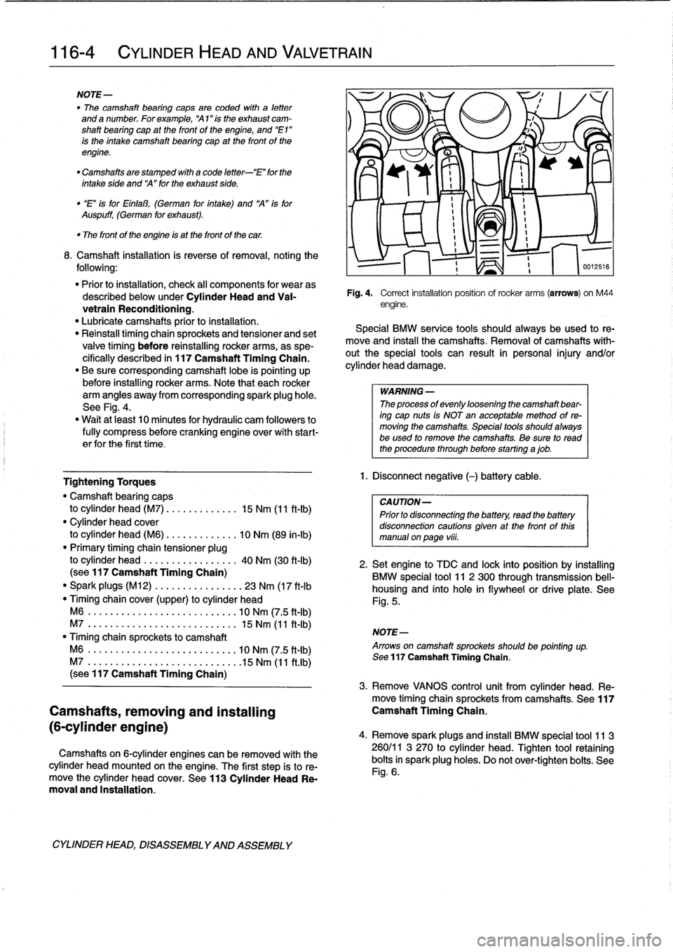
"
Be
sure
corresponding
camshaft
lobe
is
pointing
up
before
installing
rocker
arms
.
Note
that
each
rocker
arm
angles
away
from
corresponding
spark
plug
hole
.
See
Fig
.
4
.
"
Wait
at
least
10
minutes
for
hydraulic
cam
followers
to
fully
compress
before
cranking
engine
over
with
start-
er
for
the
first
time
.
Tightening
Torques
"
Camshaft
bearing
caps
to
cylinder
head
(M7)
.............
15
Nm
(11
ft-Ib)
"
Cylinder
head
cover
to
cylinder
head
(M6)
.............
10
Nm
(89
in-lb)
"
Primary
timing
chain
tensioner
plug
to
cylinder
head
.
................
40
Nm
(30
ft-lb)
(sea
117
Camshaft
Timing
Chain)
"
Spark
plugs
(M12)
.............
...
23
Nm
(17
ft-lb
Timing
chaincover
(upper)
to
cylinder
head
M6
.....
.
.
...
................
.
10
Nm
(7
.5
ft-Ib)
M7
....
..
.
.
........
.
.....
.
...
.
15
Nm
(11
ft-Ib)
"
Timing
chain
sprockets
to
camshaft
M6
....
.
.
..
..............
.
..
..
10
Nm
(7
.5
ft-Ib)
M7
....
....
..............
.
..
..
.15
Nm
(11
ft
.lb)
(sea
117
Camshaft
Timing
Chain)
Camshafts,
removing
and
installing
(6-cylinder
engine)
Camshafts
on
6-cylinder
engines
can
be
removed
with
the
cylinder
head
mounted
on
the
engine
.
The
first
step
is
to
re-
move
the
cylinder
head
cover
.
See
113
Cylinder
Head
Re-
moval
and
Installation
.
CYLINDER
HEAD,
DISASSEMBLYAND
ASSEMBLY
Fig
.
4
.
Correct
installation
position
ofrocker
arms
(arrows)
on
M44
engine
.
Special
BMW
service
tools
should
always
be
used
to
re-
move
and
instan
the
camshafts
.
Removal
of
camshafts
with-
outthe
special
tools
can
result
in
personal
injury
and/or
cylinder
head
damage
.
WARNING
-
The
processof
evenly
loosening
the
camshaft
bear-
ing
cap
nuts
is
NOT
en
acceptable
method
of
re-
moving
the
camshafts
.
Special
tools
shouldalways
be
used
lo
remove
the
camshafts
.
Be
sure
to
read
the
procedure
through
before
starting
ajob
.
1
.
Disconnect
negative
(-)
battery
cable
.
CAUTION-
Prior
to
disconnectiog
the
battery,
read
the
battery
disconnection
cautions
given
at
the
front
of
this
manual
onpaga
viii
.
516
2
.
Setengine
to
TDC
and
lock
into
position
by
installing
BMW
special
tool
11
2
300
through
transmission
bell-
housing
and
into
hole
in
flywheel
or
drive
platea
See
Fig
.
5
.
NOTE-
Arrows
on
camshaft
sprockets
shouldbe
pointing
up
.
Sea
117
Camshaft
Timing
Chain
.
3
.
Remove
VANOS
control
unit
from
cylinder
head
.
Re-
move
timing
chainsprockets
from
camshafts
.
See117
Camshaft
Timing
Chain
.
4
.
Remove
sparkplugs
and
insta¡¡
BMW
special
tool
11
3
260/11
3
270
to
cylinder
head
.
Tighten
tool
retaining
bolts
in
spark
plug
holes
.
Do
not
ovar-tighten
bolts
.
See
Fig
.
6
.
Page 97 of 759
GENERAL
......
.
.
.
.
.
.
.
.
.
...
.
.
.
.
.
.
.
.
.
.
117-1
Camshaft
timing
chains,
removing
(6-cylinder
engines)
....
.
....
..
....
..
...
.117-7
CAMSHAFT
TIMING
CHAIN,
Camshaft
timing
chains,
installing
4-CYLINDER
....
.
.
.
.
.
.
.
.
.
.
.
.......
.
...
117-2
6-clinderen
nes
117-11
Camshaft
timingchain,
removing
(
y
gi
(4-cylinder
engines)
...
..
....
..
...
...
....
117-2
VANOS
(VARIABLE
VALVE
TIMING)
.
..
117-14
Camshaft
timingchain,
installing
VANOS
system
operation,
testing
.....
.
....
117-14
(4-cylinder
engines)
...
..
...
....
..
.
.....
117-4
VANOS
control
unit,
removing
.
..
..........
117-16
CAMSHAFT
TIMINGCHAINS,
VANOS
control
unit,
installing
..
..
..........
117-17
6-CYLINDER
.
.........................
117-6
GENERAL
117
Camshaft
Timing
Chain
This
repair
group
covers
timing
chain
repair
information
for
the
4-
and
6-cylinder
engines
.
4-cylinder
enginesuse
one
double-row
chain
to
drive
the
dual
overhead
camshafts
.
See
Fig
.
1
.
Fig
.
1
.
M44
engine
valvetrain
chain
drive
.
M42
engine
is
similar
.
CAMSHAFT
TIMING
CHAIN
117-1
6-cylinder
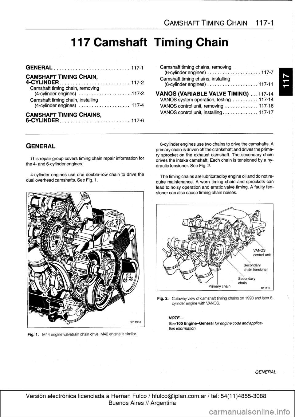
enginesusetwo
chains
to
drive
the
camshafts
.
A
primary
chain
is
driven
off
the
crankshaft
and
drives
the
prima-
ry
sprocket
on
the
exhaustcamshaft
.
The
secondary
chain
drives
the
intake
camshaft
.
Each
chain
is
tensioned
by
a
hy-
draulic
tensioner
.
See
Fig
.
2
.
The
timing
chainsare
lubricated
by
engine
oil
and
do
not
re-`
quire
maintenance
.
A
worn
timing
chain
and
sprockets
can
lead
to
noisy
operation
and
erratic
valve
timing
.
A
faulty
ten-
sioner
can
also
cause
timing
chaín
noises
.
Primarychain
NOTE-
See
100
Engine-General
for
engine
code
and
applica-
tion
information
.
Secondary
chain
tensioner
Secondary
chain
B11115
Fig
.
2
.
Cutaway
view
of
camshaft
timing
chains
on1963
and
later
6-
cylinder
engine
with
VANOS
.
GENERAL