relay diagram BMW 325i 1994 E36 Workshop Manual
[x] Cancel search | Manufacturer: BMW, Model Year: 1994, Model line: 325i, Model: BMW 325i 1994 E36Pages: 759
Page 52 of 759
100-
1
0
ENGINE-GENERAL
Table
d
.
OBD
I
Fault
(Blink)
Codes
(continued)
(1992-1995
modeis
only)
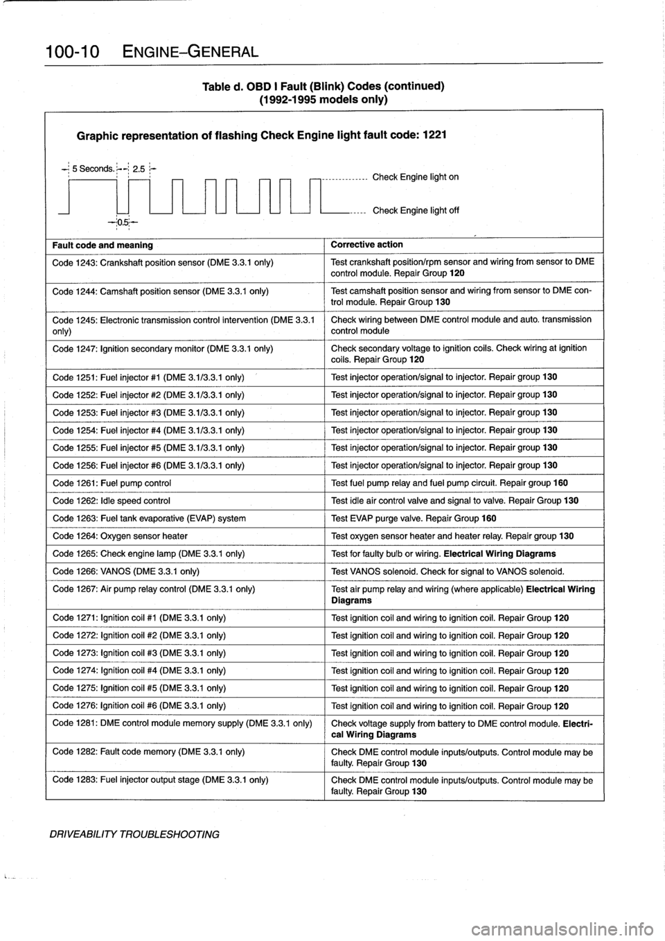
Graphic
representation
of
flashing
Check
Engine
light
fault
code
:
1221
-
;
5
Seconds
.
;--~
2
.5
r
----------------
Check
Engine
light
on
Fault
code
and
meaning
Corrective
action
Check
Engine
light
off
Code
1243
:
Crankshaft
position
sensor
(DME
3
.3
.1
only)
Test
crankshaft
position/rpm
sensor
and
wiring
from
sensor
lo
DME
control
module
.
Repair
Group
120
Code
1244
:
Camshaft
position
sensor
(DME
3
.3
.1
only)
Test
camshaft
position
sensor
and
wiring
fromsensor
to
DME
con-
trol
module
.
Repair
Group
130
Code
1245
:
Electronic
transmission
control
intervention
(DME
3
.3
.1
Check
wiring
between
DME
control
module
and
auto
.
transmission
only)
control
module
Code
1247
:
Ignition
secondary
monitor
(DME
3
.3
.1
only)
Check
secondary
voltage
lo
ignition
coils
.
Check
wiringat
ignition
coils
.
Repair
Group
120
Code
1251
:
Fuel
injector
#1
(DME
3
.113
.3
.1
only)
1
Test
injector
operation/signal
lo
injector
.
Repair
group130
Code
1252
:
Fuel
injector
#2
(DME
3
.113
.3
.1
only)
Test
injector
operation/signal
lo
injector
.
Repair
group130
Code
1253
:
Fuel
injector
#3
(DME
3
.1/3
.3
.1
only)
Test
injector
operation/signal
to
injector
.
Repair
group130
Code
1254
:
Fuel
injector
#4
(DME
3
.1/3
.3
.1
only)
Test
injector
operation/signal
to
injector
.
Repair
group
130
Code
1255
:
Fuel
injector
#5
(DME
3
.1/3
.3
.1
only)
Test
injector
operation/signal
to
injector
.
Repair
group130
Code
1256
:
Fuel
injector
#6
(DME
3
.1/3
.3
.1
only)
Test
injector
operation/signal
lo
injector
.
Repair
group130
Code
1261
:
Fuel
pump
control
Test
fuel
pump
relay
and
fuel
pump
circuit
.
Repairgroup
160
Code
1262
:
Idle
speed
control
Test
idleair
controlvalve
and
signalto
valve
.
Repair
Group
130
Code
1263
:
Fuel
tank
evaporative
(EVAP)
system
Test
EVAP
purge
valve
.
Repair
Group
160
Code
1264
:
Oxygen
sensor
heater
1
Test
oxygen
sensorheater
and
heater
relay
.
Repair
group
130
Code
1265
:
Check
engine
lamp
(DME
3
.3.1
only)
1
Test
for
faulty
bulb
or
wiring
.
Electrical
Wiring
Diagrams
Code
1266
:
VANOS
(DME
3
.3
.1
only)
1
Test
VANOS
solenoid
.
Check
for
signal
to
VANOS
solenoid
.
Code
1267
:
Air
pump
relay
control
(DME
3
.3
.1
only)
Test
air
pump
relay
and
wiring
(where
applicable)
Electrical
Wiring
Diagrams
Code
1271
:
Ignition
coil
#1
(DME
3
.3.1
only)
Test
ignitioncoil
and
wiring
toignitioncoil
.
Repair
Group
120
Code
1272
:
Ignition
coil
#2
(DME
3
.3.1
only)
Test
ignitioncoil
and
wiring
loignitioncoil
.
Repair
Group
120
Code
1273
:
Ignition
coil
#3
(DME
3
.3.1
only)
Test
ignitioncoil
and
wiring
loignitioncoil
.
Repair
Group
120
Code
1274
:
Ignítion
coil
#4
(DME
3
.3.1
only)
Test
ignitioncoil
and
wiring
toignitioncoil
.
Repair
Group
120
Code
1275
:
Ignitioncoil
#5
(DME
3
.3.1
only)
Test
ignition
coil
and
wiring
loignitioncoil
.
Repair
Group
120
Code
1276
:
Ignition
coil
#6
(DME
3
.3.1
only)
Test
ignitioncoil
and
wiring
loignitioncoil
.
Repair
Group
120
Code
1281
:
DME
control
module
memory
supply
(DME
3
.3
.1
only)
Check
voltage
supply
from
battery
lo
DME
control
module
.
Electri-
Code
1282
:
Fault
code
memory
(DME
3
.3.1
only)
Check
DME
control
module
inputs/outputs
.
Control
module
may
be
faulty
.
Repair
Group
130
Code
1283
:
Fuel
injector
output
stage
(DME
3
.3
.1
only)
Check
DME
control
module
inputs/outputs
.
Control
module
may
be
faulty
.
Repair
Group
130
DRIVEABILITY
TROUBLESHOOTING
cal
Wiring
Diagrams
Page 153 of 759
ELECTRICAL
CHECKS
AND
COMPONENT
TESTING
Main
relay,
testing
The
main
relay
is
energized
via
the
engine
control
module
and
supplies
plus
(+)
power
to
the
many
of
the
engine
man-
agement
components
and
subsystems,
including
the
fuel
pump
relay
.
If
this
relay
is
faulty,
the
engine
will
not
start
.
1
.
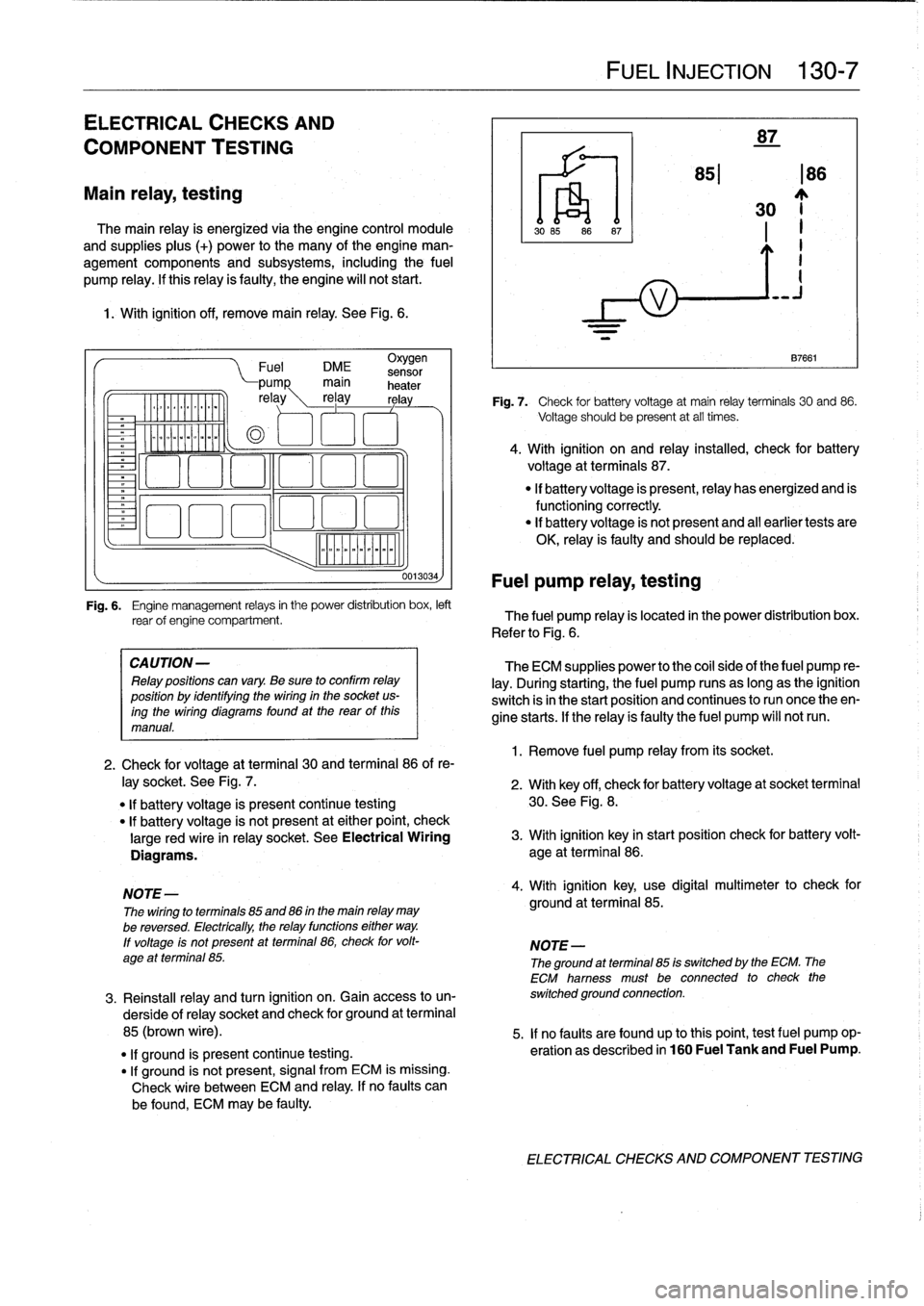
With
ignition
off,
remove
main
relay
.
See
Fig
.
6
.
.
iommooommmoi
~
"""
Fuel
DME
sensor
CA
UTION-
Relay
positions
can
vary
.
Be
sure
to
confirm
relay
position
by
identífyíng
the
wiring
in
the
socket
us-
ingthe
wiring
diagramsfound
at
the
rearof
this
manual
.
0013034)
Fuel
pump
relay,
testing
FUEL
INJECTION
130-
7
87
851186
30
~j
1
.
Remove
fuel
pump
relay
from
its
socket
.
87661
Fig
.
7
.
Check
for
battery
voltage
at
main
relay
terminals
30
and
86
.
Voltage
should
be
present
at
all
times
.
4
.
With
ignition
on
and
relay
installed,
check
for
battery
voltage
at
terminals
87
.
"
If
battery
voltage
is
present,relay
has
energized
and
is
functioningcorrectly
.
"
lf
battery
voltage
is
not
present
and
al¡
earlier
tests
are
OK,
relay
is
faulty
and
should
be
replaced
.
Fig
.
6
.
Engine
management
relays
in
the
power
distribution
box,
left
rear
of
engine
compartment
.
The
fuel
pump
relay
is
located
in
the
power
distribution
box
.
Refer
to
Fig
.
6
.
The
ECM
supplies
power
to
the
coil
side
of
the
fuel
pump
re-
lay
.
During
starting,
the
fuel
pump
runs
as
long
as
the
ignition
switch
isin
the
start
position
and
continues
to
run
once
theen-
gine
starts
.
If
the
relay
ís
faulty
the
fuel
pump
will
notrun
.
2
.
Check
for
voltage
at
terminal
30
and
terminal
86
of
re-
¡ay
socket
.
See
Fig
.
7
.
2
.
With
key
off,
check
for
batteryvoltage
at
socket
terminal
"
If
battery
voltage
is
present
continue
testing
30
.
See
Fig
.
8
.
"
lf
battery
voltage
is
not
present
at
either
point,
check
large
red
wire
in
relay
socket
.
See
Electrical
Wiring
3
.
With
ignition
key
in
start
position
check
for
battery
volt-
Diagrams
.
age
at
terminal
86
.
NOTE-
4
.
With
ignition
key,
use
digital
multimeter
to
check
for
The
wiring
to
terminals
85
and
86
in
the
main
relay
may
ground
at
terminal
85
.
be
reversed
.
Electrically,
the
relay
functions
either
way
.
lf
voltage
ís
not
present
at
terminal
86,
check
for
volt-
NOTE-
age
at
terminal
85
.
The
ground
atterminal
85
is
switched
by
the
ECM
.
The
ECM
hamess
must
be
connected
to
check
the
3
.
Reinstall
relay
and
turn
ignition
on
.
Gainaccess
to
un-
switched
ground
connection
.
derside
of
relay
socket
and
check
for
ground
at
terminal
85
(brown
wire)
.
5
.
If
no
faults
are
found
up
tothis
point,
testfuel
pump
op-
"
lf
ground
is
present
continue
testing
.
eration
as
described
in
160
Fuel
Tank
and
Fuel
Pump
.
"
If
ground
is
not
present,
signal
from
ECM
is
missing
.
Check
wire
between
ECM
and
relay
.
If
no
faults
can
be
found,
ECM
may
be
faulty
.
ELECTRICAL
CHECKS
AND
COMPONENT
TESTING
Page 154 of 759
130-
8
FUEL
INJECTION
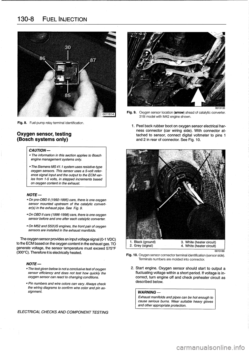
Fig
.
8
.
Fuel
pump
relayterminal
identification
.
1.
Peel
back
rubber
boot
on
oxygen
sensor
electrical
har-
ness
connector
(car
wiring
side)
.
With
connector
at-
Oxygen
sensor,
testing
tached
to
sensor,
connect
digital
voltmeter
to
pins
1
(BOSch
systems
only)
and
2
in
rear
of
connector
.
See
Fig
.
10
.
CAUTION-
"
The
information
inthis
sectionapplies
to
Bosch
engine
management
systems
only
.
"
The
Siemens
MS
41
.1
system
uses
resistive-type
oxygen
sensors
.
This
sensor
uses
a
5-volt
refer-
ence
signal
input
and
the
output
to
the
ECM
var-
ees
from
1-5
volts,
in
stepped
increments
based
on
oxygen
content
in
the
exhaust
.
NOTE-
"
On
pre-08D
11(1992-1995)
cars,
there
is
one
oxygen
sensor
mounted
upstream
of
the
catalytic
convert-
er(s)
in
the
exhaust
pipe
.
See
Fig
.
9
.
"
On
OBD
11
cars
(1996-1998)
cars,
there
is
one
oxygen
sensor
before
andone
after
each
catalytic
converter
.
"
OnM52
and
S52US
engines,
the
front
pairof
oxygen
sensors
are
installed
in
the
exhaust
manifolds
.
The
oxygen
sensor
providesan
input
voltage
signal
(0-1
VDC)
to
the
ECM
based
on
the
oxygen
content
in
the
exhaust
gas
.
TO
generate
voltage,
the
sensor
temperature
must
exceed
575°F
(300°C)
.
Therefore
it
ís
electrically
heated
.
NOTE-
"
The
test
given
below
is
not
a
conclusive
test
of
oxygen
sensor
efficiency
and
does
not
test
how
quickly
the
oxygensensor
can
react
to
changing
conditions
.
"
Pin
numbers
and
wirecolors
can
vary
.
Always
check
the
wiring
diagrams
to
conflrm
wire
color
and
pinas-
signment
.
ELECTRICAL
CHECKS
AND
COMPONENT
TESTING
0013135
Fig
.
9
.
Oxygen
sensor
location
(arrow)
ahead
of
catalytic
converter
.
3181
model
with
M42
engine
shown
.
1
.
Black
(ground)
2
.
Grey
(signal)
4
.
White
(heater
circuit)
3
.
White
(heater
circuit)
0013189
Fig
.
10
.
Oxygen
sensor
connector
terminal
identification
(sensor
sede)
.
Terminals
numbers
are
molded
into
connector
.
2
.
Start
engine
.
Oxygen
sensorshould
start
to
output
a
fluctuating
voltage
within
a
short
period
.
If
voltage
is
in-
correct,
turn
engine
off
and
check
preheater
circuit
as
described
below
.
WARNING
-
Exhaust
manifolds
and
pipes
can
be
hot
enough
to
cause
serious
burns
.
Wear
suitable
heavy
gloves
and
other
appropriate
protection
.
Page 155 of 759
Oxygen
Sensor
FUEL
DELIVERY
TESTS
FUEL
INJECTION
130-
9
"
Voltage
at
¡dle
..
.
..
..
....
0
.2
to
0
.8
VDC,
fluctuating
Checking
fuel
delivery
is
afundamental
part
of
trouble-
shooting
and
diagnosing
the
engine
management
system
.
Fuel
pressure
directly
influences
fuel
delivery
.
An
accurate
NOTE-
fuel
pressure
gauge
will
be
needed
to
make
the
tests
.
To
check
sensorresponse
to
lean
and
rich
mixtures,
createenairleak,
orpull
vacuumhoseofffue¡
pressure
There
are
three
significant
fuel
delivery
values
to
be
mea-
regulator
to
increase
fuel
pressure
.
sured
:
3
.
Separate
sensorharness
connector
from
sensor
.
Check
for
battery
voltage
between
terminals
3
and
4
(green
wire
and
brown
wire)
in
main
wiring
harness
side
of
con-
nector
with
engine
running
.
If
voltage
is
not
present,
check
oxygen
sensor
heater
relay
.
See610
Electrical
Component
Locations
.
4
.
Check
heater
element
resistance
between
terminals
3
and
4
in
sensor
side
of
connector
.
If
element
is
electri-
cally
open
(no
continuity),
replace
sensor
.
NOTE-
The
oxygen
sensor
heater
relay
is
mounted
in
the
main
power
distributfon
box
in
the
left
rear
of
the
engine
com-
partment
.
Refer
to
Fig
.
6
.
The
heater
relay
is
energized
wíth
positive
(+)
battery
voltage
from
the
main
relayanda
switched
ground
from
the
ECM
.
See
Electrical
Wir-
ing
Diagrams
.
"
Oxygen
sensor
to
exhaust
pipe
...
..
55
Nm
(41
ft-Ib)
"
System
pressure-created
by
the
fuel
pump
and
main-
tained
by
the
pressure
regulator
.
"
Fuel
delivery
volume-created
by
the
fuel
pump
and
af-
fected
by
restrictions,
suchasclogged
fuel
filter
.
"
Residual
pressure-the
pressure
maintained
in
the
closed
system
after
the
engine
and
fuel
pump
are
shut
off
.
Procedures
for
measuring
the
first
two
quantities
arede-
scribed
in
160
Fuel
Tank
and
Fuel
Pump
.
Residual
fuel
pres-
sure
is
checked
using
the
procedure
detailed
later
in
this
group
.
Operating
fuel
pump
fortests
To
operate
the
fuel
pump
for
testing
purposes
without
hav-
íng
to
runthe
engine,
the
fuel
pump
relay
can
be
bypassed
to
power
the
pump
directly
.
Fuel
pump
relay
location
is
shown
in
Fig
.
6
.
5
.
¡f
oxygen
sensor
doesn't
produce
a
fluctuating
voltage
To
runthe
fuel
pump,
remove
the
fuel
pump
relay
and
con-
and
preheater
circuit
is
OK,
replace
sensor
.
nect
the
socket
for
relayterminal
30
to
the
socket
for
relay
ter-
mina¡
87
with
a
fused
jumper
wire
.
After
completing
the
tests,
NOTE-
remove
the
jumper
wire
.
If
not
already
applied,
coat
the
oxygen
sensor
threads
with
an
anti-seize
compound
before
installation
.
Do
not
CAUTION-
getthe
compound
on
the
sensor
tip
.
"
Relay
locations
may
vary
.
Use
care
when
identi-
fying
relays
and
making
electrical
checks
at
the
fuselrelay
panel
.
See
610
Electrical
Compo
Tightening
Torque
nent
Locations
for
additional
relay
information
.
"
The
fuel
pump
relay
has
a
1
.5
mm2
red
wire
at
ter-
minal
30
in
the
relay
socket
.
Terminal
87
has
a
1
.5
mm
2
greenlviolet
wire
.
See
Electrical
Wiring
Di-
agrams
for
additional
wiring
information
.
NOTE-
Thejumper
wire
should
be
1.5
mm2
(14
ga
.)
and
in-
clude
an
in-line
tuse
holder
with
a15
amp
tuse
.
To
avoid
fuselrelay
panel
damage
from
repeated
connect-
ing
and
disconnecting,
also
include
a
toggle
switch
.
A
heavy-duty
jumper,
BMW
tool
no
.
61
3
050,
is
also
available
from
an
authorized
BMW
dealer
.
FUEL
DELIVERYTESTS
Page 166 of 759
130-20
FUEL
INJECTION
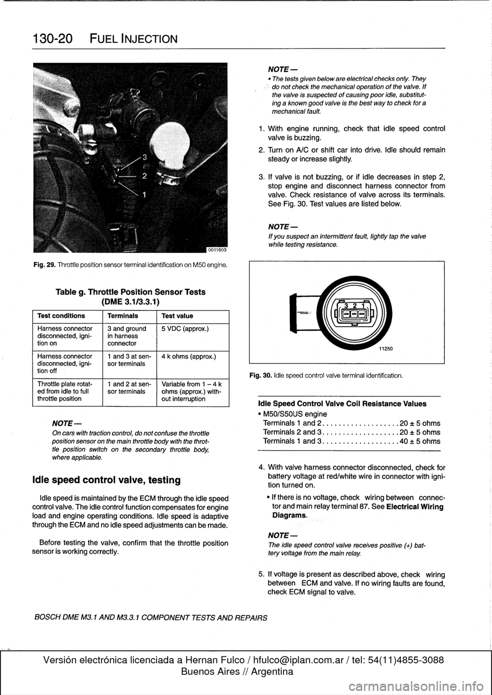
Fig
.
29
.
Throttleposition
sensor
terminal
identification
on
M50
engine
.
Tableg
.
Throttle
Position
Sensor
Tests
(DME3
.113
.3
.1)
Test
conditions
I
Terminals
I
Testvalue
Harness
connector
13
andground
15
VDC
(approx
.)
disconnected,
igni-
in
harness
tion
on
connector
Harness
connector
1
and3
at
sen-
14
k
ohms
(approx
.)
disconnected,
igni-
sor
terminals
tion
off
Throttle
plate
rotat-
1
and
2
at
sen-
Variable
from
1
-
4ked
from
¡dieto
full
sor
terminals
ohms
(approx
.)
with-
throttle
position
out
interruption
¡die
Speed
Control
Valve
Coil
Resistance
Values
"
M50/S50US
engine
NOTE-
Terminals
1
and
2
..
.
................
20
t
5
ohms
On
cars
with
tractioncontrol,
do
not
confuse
the
throttle
Terminals
2
and
3
...................
20
t5
ohms
position
sensor
on
the
main
throttle
body
with
the
throt-
Terminals
1
and
3
..
.
..
:
............
.40
t
5
ohms
tle
positionswitch
on
the
secondary
throttle
body,
where
applicable
.
¡die
speed
control
valve,
testing
¡die
speed
is
maintained
by
the
ECM
through
the
¡die
speed
control
valve
.
The
¡die
controlfunction
compensates
for
engine
load
and
engine
operating
conditions
.
¡die
speed
is
adaptive
through
the
ECM
and
no
¡die
speed
adjustments
can
be
made
.
NOTE-
Before
testing
the
valve,
confirm
that
the
throttle
position
The
idle
speed
controlvalve
receives
positive
(+)
bat-
sensor
is
working
correctly
.
tery
voltage
from
the
main
relay
.
BOSCH
DME
M3
.
1
AND
M3
.3
.1
COMPONENT
TESTS
AND
REPAIRS
NOTE-
"
The
tests
given
below
are
electrical
checks
only
.
They
do
not
check
the
mechanical
operation
of
the
valve
.
If
the
valve
is
suspected
of
causing
poor
idie,
substitut-
ing
a
known
good
valve
is
the
best
way
to
check
for
a
mechanical
fault
.
1
.
With
engine
running,
check
that
¡die
speed
control
valve
is
buzzing
.
2
.
Turn
on
A/C
or
shift
car
finto
drive
.
¡die
should
remain
steady
orincrease
slightly
.
3
.
If
valve
is
not
buzzing,or
if
¡die
decreases
in
step
2,
stop
engine
and
disconnect
harness
connector
from
valve
.
Check
resistance
of
valve
across
its
terminals
.
See
Fig
.
30
.
Test
values
are
listed
below
.
NOTE
-
If
you
suspect
an
intermittent
fault,
lightly
tapthe
valve
while
testing
resistance
.
11250
Fig
.
30
.
¡die
speed
control
valve
terminal
identification
.
4
.
With
valve
harnessconnector
disconnected,
check
for
battery
voltage
at
red/white
wire
in
connector
with
igni-
tion
tumed
on
.
"
If
there
is
no
voltage,
check
wiring
between
connec-
tor
and
main
relayterminal
87
.
See
Electrical
Wiring
Diagrams
.
5
.
If
voltage
is
presentas
described
above,
check
wiring
between
ECM
and
valve
.
If
no
wiring
faults
are
found,
check
ECM
signal
to
valve
.
Page 173 of 759
0013ZIM
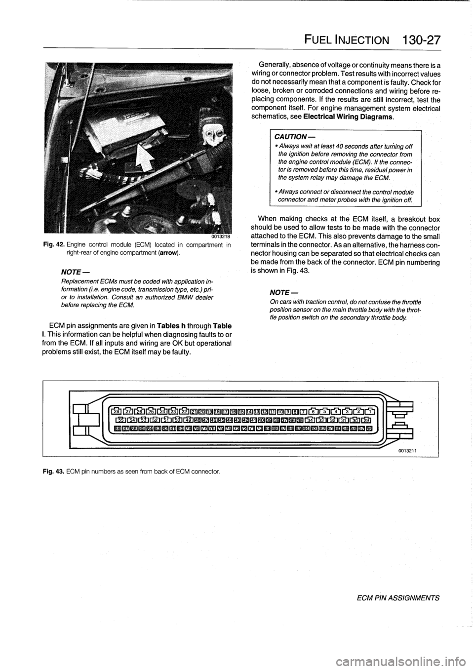
Fig
.
42
.
Engine
control
module
(ECM)
located
in
compartment
in
right-rearof
engine
compartment
(arrow)
.
NOTE-
Replacement
ECMs
must
be
coded
with
application
in-
formation
(Le
.
engine
code,
transmission
type,
etc
.)
pri-
or
to
installation
.
Consult
an
authorized
BMW
dealer
before
replacing
the
ECM
.
ECM
pin
assignments
are
given
in
Tables
h
through
Table
I.
This
information
can
be
helpful
when
diagnosing
faultsto
or
from
the
ECM
.
If
al¡
inputs
and
wiring
are
OK
butoperational
problems
still
exist,
the
ECM
itself
may
be
faulty
.
Fig
.
43
.
ECM
pin
numbers
as
seen
from
back
of
ECM
connector
.
FUEL
INJECTION
130-
2
7
Generally,
absence
of
voltage
or
continuity
means
there
is
a
wiring
or
connector
problem
.
Test
results
with
incorrect
values
do
notnecessarily
mean
that
a
component
is
faulty
:
Check
for
loose,
broken
or
corroded
connections
and
wiring
before
re-
placing
components
.
If
the
results
are
still
incorrect,
test
the
component
itself
.
For
engine
management
system
electrical
schematics,
see
Electrical
Wiring
Diagrams
.
CAUTION-
Always
waitat
least
40
seconds
after
tuniing
off
the
ignition
before
removing
the
connector
from
the
engine
control
module
(ECM)
.
If
the
connec-
tor
is
removed
before
this
time,
residual
power
in
the
system
relay
may
damage
the
ECM
.
"
Always
connector
disconnect
the
control
module
connector
and
meter
probes
with
the
ignitionoff
.
When
making
checks
at
the
ECM
itself,
a
breakout
box
should
be
used
to
allow
tests
to
be
made
with
the
connector
attached
to
the
ECM
.
This
also
prevents
damage
tothe
small
termínals
in
the
connector
.
As
an
alternative,
theharness
con-
nector
housing
can
be
separated
so
that
electrical
checks
can
be
made
from
the
back
of
the
connector
.
ECM
pin
numbering
is
shown
in
Fig
.
43
.
NOTE
-
On
cars
with
tractioncontrol,
do
not
confuse
the
throttle
position
sensor
on
the
main
throttle
body
with
the
throt-
tle
position
switch
on
the
secondary
throttle
body
.
27
Lb
2L4
LJ
22
©©®®17
©©®©©~©©®©~~rui~~ru
®®®®®®®®®®®®®®®IZA®®®®®®®®®®®®®®®®®
1
>I-
0013211
ECM
PIN
ASSIGNMENTS
Page 191 of 759
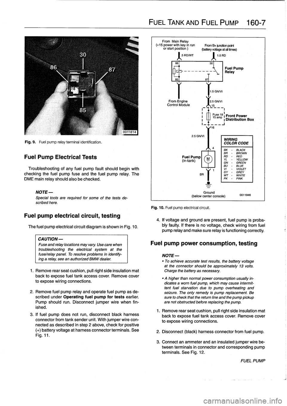
Fig
.
9
.
Fuel
pump
relay
terminal
identification
.
Fuel
Pump
Electrical
Tests
Troubleshooting
of
any
fuel
pump
fault
should
begin
with
checking
the
fuel
pump
fuse
and
the
fuel
pump
relay
.
The
DME
main
relay
should
also
be
checked
.
NOTE-
Special
tools
are
requíred
for
some
of
the
tests
de-
scribed
here
.
Fuel
pump
electrical
circuit,
testing
The
fuel
pump
electrical
circuit
diagram
is
shown
in
Fig
.
10
.
3
.
If
fuel
pump
does
not
run,
disconnect
black
harness
connector
from
tank
sender
unit
.
With
jumper
wire
con-
nectedas
described
in
step
2
above,
check
for
positive
(+)
batteryvoltage
at
harness
connector
terminals
.
See
Fig
.
11
.
FUEL
TANK
AND
FUEL
PUMP
160-
7
From
Main
Relay
(+15
power
with
key
in
run
From
B+juretion
point
orstartposition)
(batteryvoRageatalltirnes)
'
.5
RD/Nrr
1
.5
RD
1
.5
GNNI
From
Engine
2
.5
GNNI
Control
Module
15
2
.5
GNNI
Ground
(below
center
console)
Fig
.
10
.
Fuel
pump
electrical
circuit
.
30
-~
Relay
Fuel
Pump
8~T
I
1
s
ám
61
Front
Power
I
a
1
Distribution
Box
I_
16
WIRING
COLOR
CODE
BK
-
BLACK
BR
-
BROWN
Fuel
Pump
RD
-
RED
(in-tank)
M
YL
YELLOWGN
-
GREENBU
-
BLUE
1
VI
-
VIOLET
GY
-
GREY
WT
-
WHITE
PK
-
PINK
0011946
4
.
If
voltage
and
groundare
present,
fuel
pump
is
proba-
bly
faulty
.
If
there
is
no
voltage,
check
wiring
From
fuel
pump
Reay
and
make
sure
Reay
is
functioning
correctly
.
CAUTION-
Fuseandrelaylocationsmayvary
.
Usecara
when
Fuel
pump
power
consumption,
testing
troubleshooting
the
electrical
system
at
the
fuselrelay
panel
.
To
resolve
problems
in
identify-
NOTE-
ing
a
relay,
see
en
authorízed
BMW
dealer
.
"
To
achieveaccurate
testresults,
fhe
battery
voltage
at
the
connector
should
be
approximately
13
volts
.
1.
Remove
rearseat
cushion,
pull
right
side
insulation
mat
Charge
the
battery
asnecessary
.
back
to
expose
fuel
tank
accesscover
.
Remove
cover
.
q
higher
than
normal
power
consumption
usually
fin-
to
expose
wiring
connections
.
dicates
a
worn
fuel
pump,
which
may
cause
intermit-
tentfuel
starvation
due
lo
pump
overheating
and
2
.
Remove
fuel
pump
relay
and
opérate
fuel
pump
as
de-
seizure
.
The
only
remedy
is
pump
replacement
.
Be
scribed
under
Operating
fuel
pump
for
tests
earlier
.
sure
to
check
that
thereturn
fine
and
the
pump
pickup
Pump
should
run
.
Disconnect
jumper
wire
when
fin-
are
not
obstructed
before
replacing
the
pump
.
ished
.
1
.
Remove
rear
seat
cushion,
pull
right
side
insulation
mal
back
to
expose
fuel
tank
accesscover
.
Remove
cover
to
expose
wiring
connections
.
2
.
Disconnect
(black)
harness
connector
from
fuel
pump
.
3
.
Connect
an
ammeter
and
an
insulated
jumper
wire
be-
tween
terminals
in
connector
and
corresponding
pump
terminals
.
See
Fig
.
12
.
FUEL
PUMP
Page 199 of 759
NOTE-
Some
cars
covered
by
this
manual
may
have
an
alter-
nate
cooling
fan
switchwith
switching
temperatures
of
176%190W
(80%88°C)
.
When
replacing
the
switch
check
theswitching
specifications,
whichshouldbe
stamped
on
the
switch
body
.
1
.
If
coolant
is
circulating
at
normal
operating
tempera-
ture,
but
auxiliary
cooling
fan
does
not
run,
disconnect
connector
from
radiator
temperature
switch
and
make
tests
listed
in
Table
c
.
Table
c
.
Auxiliary
Cooling
Fan
Temperature
Switch
Tests
Wires
jumpered
Test
Test
resuits
conditions
Black/green
(terminal2)
and
Ignition
ON
Fan
runs
on
brown
(terminal
1)
low
speed
Black/gray
(terminal
3)
and
Ignition
ON
Fan
runson
brown
(terminal
I
1)
high
speed
2
.
If
fan
runs
only
when
powered
directly
by
jumpered
connector
and
hot
coolant
is
circulating
through
radia-
tor,
radiator
temperature
switch
is
most
likelyfaulty
.
Use
a
new
sealing
ring
when
replacing
switch
Tightening
Torque
"
Temperature
switch
to
radiator
......
15
Nm
(11
ft-Ib)
3
.
If
auxiliary
fan
does
notrun
when
powered
directly,
check
for
battery
voltage
at
temperature
switch
connec-
tor
(black/green
wire)
with
ignition
on
.
If
battery
voltage
is
not
present,
check
fuses
.
See
610
Electrical
Com-
ponent
Locations
.
RADIATOR
AND
COOLING
SYSTEM
170-
5
~r~nmm
a
00
0
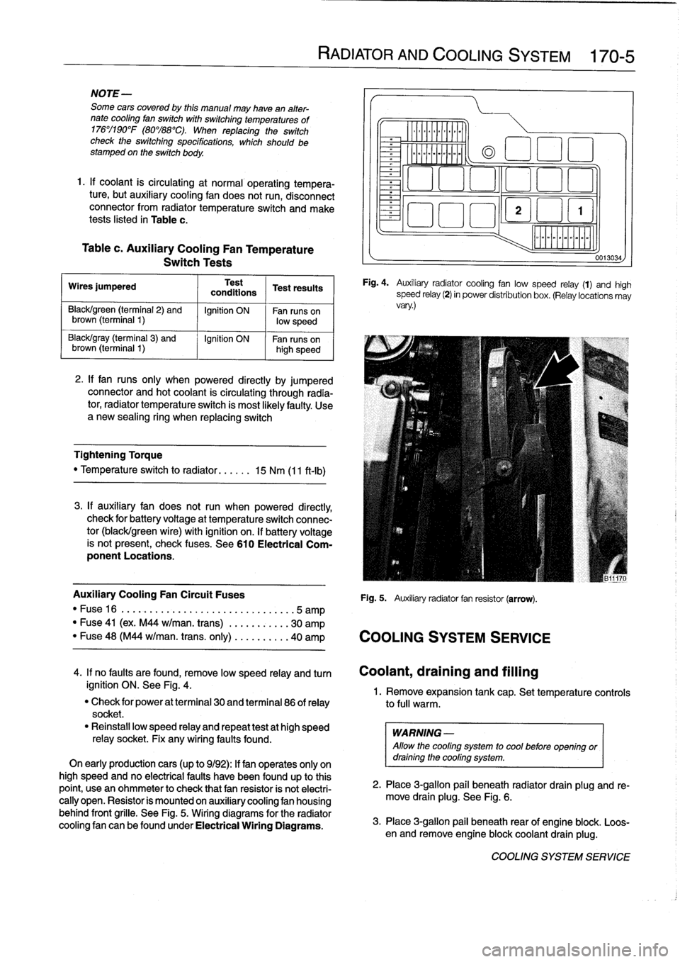
Fig
.
4
.
Auxiliary
radiator
cooling
fan
low
speed
relay
(1)
and
high
speed
relay
(2)
in
power
distribution
box
.
(Relay
locations
may
vary
.)
Auxiliary
Cooling
Fan
Circuit
Fuses
Fig
.
5
.
Auxiliary
radiator
fan
resistor
(arrow)
.
"
Fuse16
.
...................
..
..
...
...
.5
amp
"
Fuse
41
(ex
.
M44
w/man
.
trans)
.
..
.
..
.....
30
amp
"
Fuse
48
(M44
w/man
.
trans
.
only)
..
.
..
.....
40
amp
COOLING
SYSTEM
SERVICE
0013034
4
.
If
no
faults
are
found,
remove
low
speed
relay
and
turn
Coolant,draining
and
filling
ignition
ON
.
See
Fig
.
4
.
1
.
Remove
expansion
tank
cap
.
Set
temperature
controls
"
Check
for
power
at
terminal
30
and
terminal
86
of
relay
to
full
warm
.
socket
.
"
Reinstall
low
speed
relay
and
repeat
testat
high
speed
WARNING
-
relay
socket
.
Fix
any
wiring
faults
found
.
Allow
the
cooling
system
to
cool
before
openlng
or
On
early
productioncars
(up
to
9/92)
:
If
fan
operates
only
on
draining
the
cooling
system
.
high
speed
and
no
electrical
faults
have
been
foundup
to
this
point,
usean
ohmmeter
to
check
that
fan
resistor
is
not
electri-
2
.
Place
3
ra
allo
ug
.
beneath
radiator
drain
plug
and
re-
cally
open
.
Resistor
is
mounted
on
auxiliary
cooling
fan
housing
move
drain
plg
.
See
Fig
.
6
.
behind
front
grille
.
See
Fig
.
5
.
Wiring
diagrams
for
the
radiator
cooling
fan
canbefoundunder
Electrical
Wiring
Diagrams
.
3
.
Place
3-g
pail
beneath
rear
of
engine
blo
.
Loos-
en
and
re
mlon
ove
engine
blockcoolant
drain
plug
k
.
COOLING
SYSTEM
SERVICE
Page 381 of 759
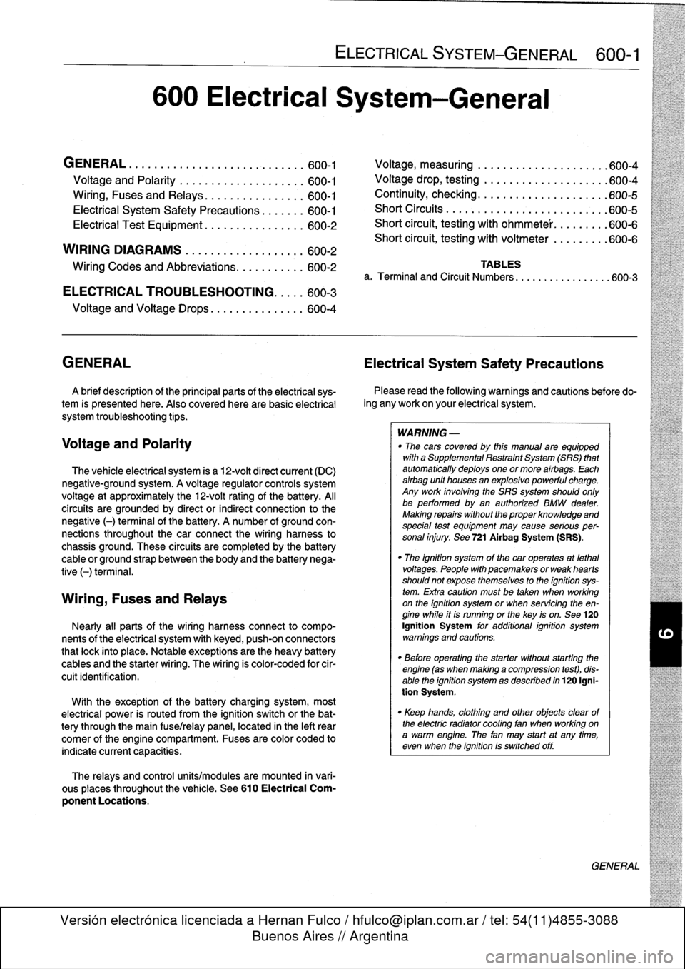
600
Electrical
System-General
GENERAL
.
...........
.
.
.
.
.
.
.
.
.
...
.
...
600-1
Voltage
and
Polarity
........
.
.
.
.
.
.
.
.....
600-1
Ming,
Fuses
and
Relays
............
.
.
.
.
600-1
Electrical
System
Safety
Precautions
...
.
.
.
.
600-1
Electrical
Test
Equipment
.....
.
.
.
....
.
.
.
.
600-2
WIRING
DIAGRAMS
..
.
.
.
.
.
.
.
.
.
........
600-2
Ming
Codes
and
Abbreviations
..
.
...
.
....
600-2
ELECTRICAL
TROUBLESHOOTING
..
.
..
600-3
Voltage
and
Voltage
Drops
..........
.
.
.
.
.
600-4
GENERAL
Electrical
System
Safety
Precautions
A
brief
description
of
the
principal
parts
of
the
electrical
sys-
tem
is
presented
here
.
Also
covered
here
are
basic
electrical
system
troubleshooting
tips
.
Voltage
and
Polarity
The
vehicle
electrical
system
is
a
12-volt
direct
current
(DC)
negative-ground
system
.
A
voltage
regulator
controls
system
voltage
at
approximately
the
12-volt
rating
of
the
battery
.
Al¡
circuits
are
grounded
by
direct
or
indirect
connection
to
the
negative
(-)
terminal
of
the
battery
.
A
number
of
ground
con-
nections
throughout
the
car
connect
the
wiring
harness
to
chassis
ground
.
These
circuits
are
completedby
the
battery
cable
or
ground
strap
between
the
body
and
the
battery
nega-
tive
(-)
terminal
.
Wiring,
Fuses
and
Relays
Nearly
all
parts
of
the
wiring
harnessconnect
to
compo-
nents
of
the
electrical
system
with
keyed,
push-on
connectors
that
lock
into
place
.
Notable
exceptions
arethe
heavy
battery
cables
and
the
starter
wiring
.
The
wiring
is
color-coded
for
cir-
cuitidentification
.
With
theexception
of
the
battery
charging
system,
most
electrical
power
is
routed
from
the
ignition
switch
or
the
bat-
tery
through
the
main
fuse/relay
panel,
located
in
¡he
left
rear
comer
of
the
engine
compartment
.
Fuses
are
color
coded
to
indicate
current
capacities
.
The
relays
and
control
units/modules
are
mounted
in
vari-
ous
places
throughout
the
vehicle
.
See610
Electrical
Com-
ponent
Locations
.
ELECTRICAL
SYSTEM-GENERAL
600-1
Voltage,
measuring
.
.
.
................
.
.
600-4
Voltage
drop,
testing
.
.
.....
.
.....
.
......
600-4
Continuity,
checking
..
.
...
.
.
.
.
.
.
.
.
.
.
.
.
.
.
.
600-5
Short
Circuits
.
.
.
.
.
.
.
.
.....
.
...
.
.
.
.
.
.
.
.
.
600-5
Short
circuit,
testing
with
ohmmete'r
.
.
.
.
.
.
.
.
.
600-6
Short
circuit,
testing
with
voitmeter
.
.
.
.
.
.
.
.
.
600-6
TABLES
a
.
Terminal
and
Circuit
Numbers
..............
..
.600-3
Please
read
the
following
warnings
and
cautions
before
do-
ing
any
work
on
your
electrical
system
.
WARNING
-
"
The
cars
covered
by
this
manual
are
equipped
with
aSupplemental
Restraint
System
(SRS)
that
automatically
deploys
one
or
more
airbags
.
Each
airbag
unit
houses
an
explosive
powerful
charge
.
Any
work
involving
the
SRS
system
should
only
be
performed
byan
authorized
BMW
dealer
.
Making
repairs
without
the
proper
knowledge
and
special
test
equipment
may
cause
serious
per-
sonal
injury
.
See
721
Airbag
System
(SRS)
.
"
The
ignition
system
of
the
car
operates
at
lethal
voltages
.
People
with
pacemakers
or
weak
hearts
should
not
expose
themselves
to
the
ignition
sys-
tem
.
Extra
caution
mustbe
taken
when
working
on
the
ignition
system
or
when
servicing
theen-
gine
while
it
is
runningor
the
key
is
on
.
See
120
Ignition
System
for
additional
ignition
system
warnings
and
cautions
.
"
Before
operating
the
starter
without
starting
the
engine
(as
when
making
a
compressfon
test),
dis-
able
the
ignition
system
as
described
in
120
Igni-
tion
System
.
"
Keep
hands,
clothing
and
other
objects
clear
of
the
electric
radiator
coollng
fan
when
working
on
a
warm
engine
.
The
fan
may
start
at
any
tíme,
even
when
the
ignition
is
switched
off
.
GENERAL
Page 382 of 759
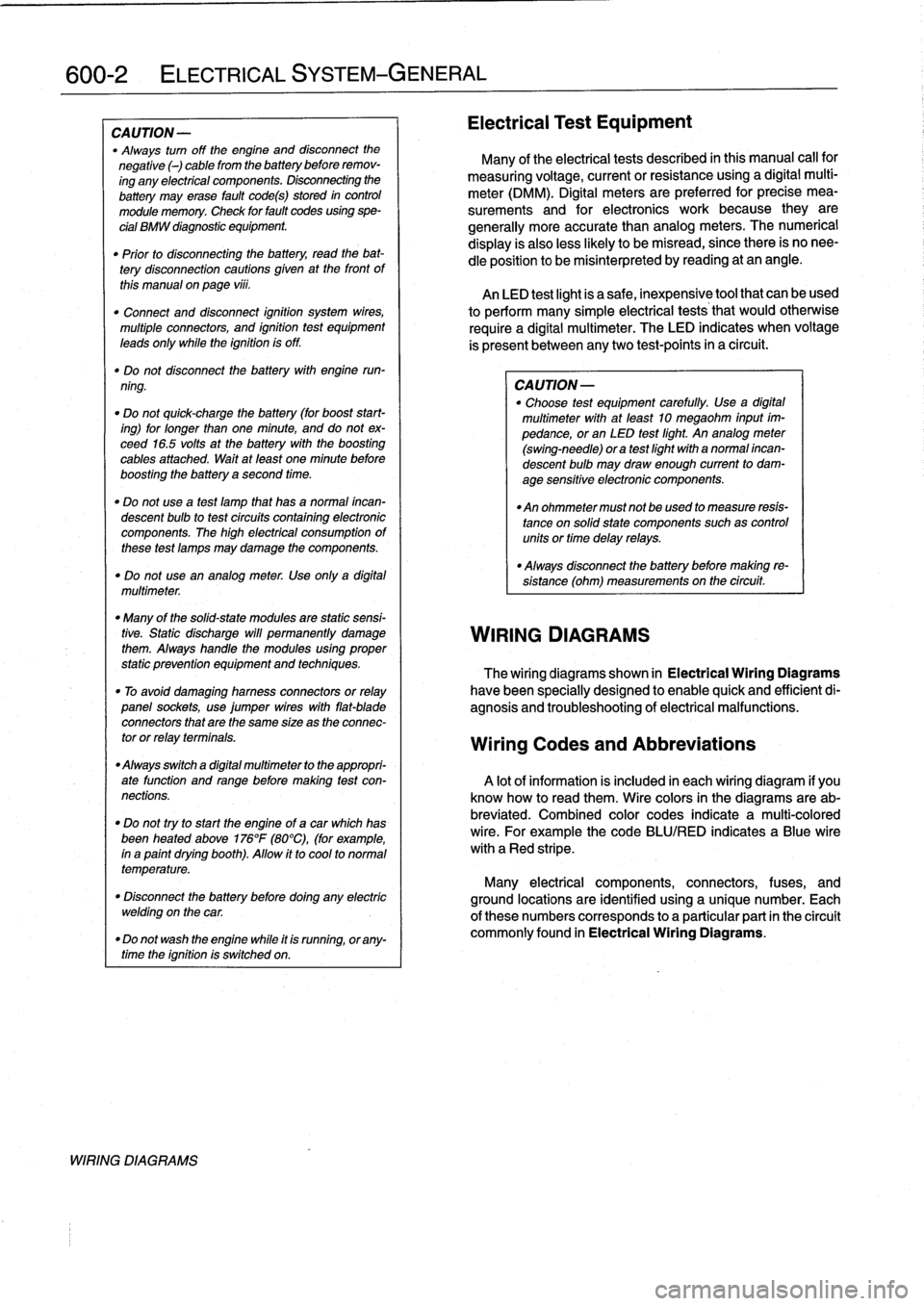
600-2
ELECTRICAL
SYSTEM-GENERAL
CAUTION
-
"
Always
turn
off
the
engine
and
disconnect
the
negative
()
cable
from
the
batterybefore
remov-
ing
any
electrical
components
.
Disconnecting
the
battery
may
erase
fault
code(s)
stored
in
control
module
memory
.
Check
for
fault
codes
using
spe-
cial
BMW
diagnostic
equipment
.
"
Prior
to
disconnecting
the
battery,
read
the
bat-
tery
disconnection
cautions
given
at
the
front
of
this
manual
onpage
viii
.
"
Connect
and
disconnect
ignition
system
wires,
multiple
connectors,
and
ignition
test
equipment
leads
only
while
the
ignition
is
off
.
"
Do
not
disconnect
the
battery
with
engine
run-
ning
.
"
Do
not
quick-charge
the
battery
(for
boost
start-
ing)
for
longer
than
one
minute,
and
do
not
ex-
ceed
16
.5
volts
at
the
battery
with
the
boosting
cables
attached
.
Wait
at
feast
one
minute
before
boosting
the
battery
a
second
time
.
"
Do
not
usea
test
famp
that
has
a
normal
incan-
descent
bulb
to
test
circuits
contafning
electronic
components
.
The
high
electrical
consumptionof
these
test
lamps
may
damage
the
components
.
"
Do
not
use
an
analog
meter
.
Use
onfy
a
digital
multimeter
.
"
Many
of
the
solid-state
modules
are
static
sensi-
tive
.
Static
discharge
will
permanently
damage
them
.
Always
handle
the
modules
using
proper
static
prevention
equipment
and
techniques
.
"
To
avoid
damaging
harness
connectors
or
relay
panel
sockets,
use
jumper
wires
with
flat-blade
connectors
that
are
the
same
size
as
the
connec-
tor
or
relay
terminals
.
"
Always
switch
a
digital
multimeter
to
the
appropri-
ate
function
and
range
before
making
test
con-
nections
.
"
Do
not
tryto
start
the
engine
of
a
carwhich
has
been
heated
above176°F
(80°C),
(for
example,
in
a
paint
dryingbooth)
.
Allow
it
to
cool
to
normal
temperature
.
"
Disconnect
the
battery
before
dolng
any
electric
welding
on
the
car
.
"
Do
not
wash
the
engine
while
it
is
runnfng,
or
any-
time
the
ignition
is
switched
on
.
WIRING
DIAGRAMS
Electrical
Test
Equipment
Many
of
the
electrical
tests
described
in
this
manual
call
for
measuring
voltage,
currentorresistanceusing
a
digital
multi-
meter
(DMM)
.
Digital
meters
are
preferred
for
precise
mea-
surements
and
for
electronics
work
because
they
are
generally
more
accuratethan
analog
meters
.
The
numerical
display
is
alsoless
likely
to
be
misread,
since
there
is
no
nee-
dle
position
to
be
misinterpreted
by
reading
at
an
angle
.
An
LED
test
light
is
a
safe,
inexpensive
tool
that
can
be
used
to
perform
many
simple
electrical
tests
that
would
otherwise
require
a
digital
multimeter
.
The
LED
indicates
when
voltage
is
present
between
anytwo
test-points
in
a
circuit
.
CA
UTION-
"
Choose
test
equipment
carefully
.
Use
a
digital
multimeter
with
at
leadt
10
megaohm
input
im-
pedance,or
an
LED
test
light
.
An
analog
meter
(swing-need1e)
ora
test
light
with
a
normal
incan-
descent
bulb
may
draw
enough
current
to
dam-
age
sensitive
electronic
components
.
"
An
ohmmeter
must
not
beused
to
measure
resis-
tance
on
solidstate
components
suchas
controlunits
or
time
delay
relays
.
"
Always
disconnect
the
battery
before
making
re-
sístance
(ohm)
measurements
on
the
circuit
.
WIRING
DIAGRAMS
The
wiring
diagrams
shown
in
Electrical
Wiring
Diagrams
have
been
specially
designed
to
enable
quick
and
efficientdi-
agnosis
and
troubleshooting
of
electrical
malfunctions
.
Wiring
Codes
and
Abbreviations
A
lot
of
information
is
included
in
each
wiring
diagram
if
you
know
how
to
read
them
.
Wire
colors
in
the
diagrams
are
ab-
breviated
.
Combined
color
codes
indicate
a
multi-colored
wire
.
For
example
the
code
BLU/RED
indicates
a
Blue
wire
with
a
Red
stripe
.
Many
electrical
components,
connectors,
fuses,
and
ground
locations
are
identified
using
a
unique
number
.
Each
of
there
numbers
corresponds
to
a
particular
part
in
the
circuit
commonly
found
in
Electrical
Wiring
Diagrams
.