spark plug cable position BMW 325i 1994 E36 Workshop Manual
[x] Cancel search | Manufacturer: BMW, Model Year: 1994, Model line: 325i, Model: BMW 325i 1994 E36Pages: 759
Page 88 of 759

116-
4
CYLINDER
HEAD
AND
VALVETRAIN
NOTE-
"
The
camshaft
bearing
caps
are
coded
with
a
letter
anda
number
.
Forexample,
'541"is
the
exhaustcam-
shaft
bearing
cap
at
the
front
of
the
engine,
and
`El"
is
the
intake
camshaft
bearing
cap
at
the
front
of
the
engine
.
"
Camshafts
are
stamped
with
a
code
letter-'E"
for
the
intakeside
and
A"
for
the
exhaust
side
.
"
"E"
isfor
Einla3,
(German
for
intake)
and
A"
is
for
Auspuff,
(Germen
for
exhaust)
.
"
The
front
of
the
engine
is
at
the
front
of
the
car
.
8
.
Camshaft
installation
is
reverse
of
removal,
noting
the
following
:
"
Prior
to
installation,
check
all
components
for
wear
as
described
below
underCylinder
Head
and
Val-
vetrain
Reconditioning
.
"
Lubricate
camshafts
prior
to
installation
.
"
Reinstall
timing
chain
sprockets
and
tensioner
and
set
valve
timing
before
reinstalling
rocker
arms,as
spe-
cifically
described
in
117
Camshaft
Timing
Chain
.
"
Be
sure
corresponding
camshaft
lobe
is
pointing
up
before
installing
rocker
arms
.
Note
that
each
rocker
arm
angles
away
from
corresponding
spark
plug
hole
.
See
Fig
.
4
.
"
Wait
at
least
10
minutes
for
hydraulic
cam
followers
to
fully
compress
before
cranking
engine
over
with
start-
er
for
the
first
time
.
Tightening
Torques
"
Camshaft
bearing
caps
to
cylinder
head
(M7)
.............
15
Nm
(11
ft-Ib)
"
Cylinder
head
cover
to
cylinder
head
(M6)
.............
10
Nm
(89
in-lb)
"
Primary
timing
chain
tensioner
plug
to
cylinder
head
.
................
40
Nm
(30
ft-lb)
(sea
117
Camshaft
Timing
Chain)
"
Spark
plugs
(M12)
.............
...
23
Nm
(17
ft-lb
Timing
chaincover
(upper)
to
cylinder
head
M6
.....
.
.
...
................
.
10
Nm
(7
.5
ft-Ib)
M7
....
..
.
.
........
.
.....
.
...
.
15
Nm
(11
ft-Ib)
"
Timing
chain
sprockets
to
camshaft
M6
....
.
.
..
..............
.
..
..
10
Nm
(7
.5
ft-Ib)
M7
....
....
..............
.
..
..
.15
Nm
(11
ft
.lb)
(sea
117
Camshaft
Timing
Chain)
Camshafts,
removing
and
installing
(6-cylinder
engine)
Camshafts
on
6-cylinder
engines
can
be
removed
with
the
cylinder
head
mounted
on
the
engine
.
The
first
step
is
to
re-
move
the
cylinder
head
cover
.
See
113
Cylinder
Head
Re-
moval
and
Installation
.
CYLINDER
HEAD,
DISASSEMBLYAND
ASSEMBLY
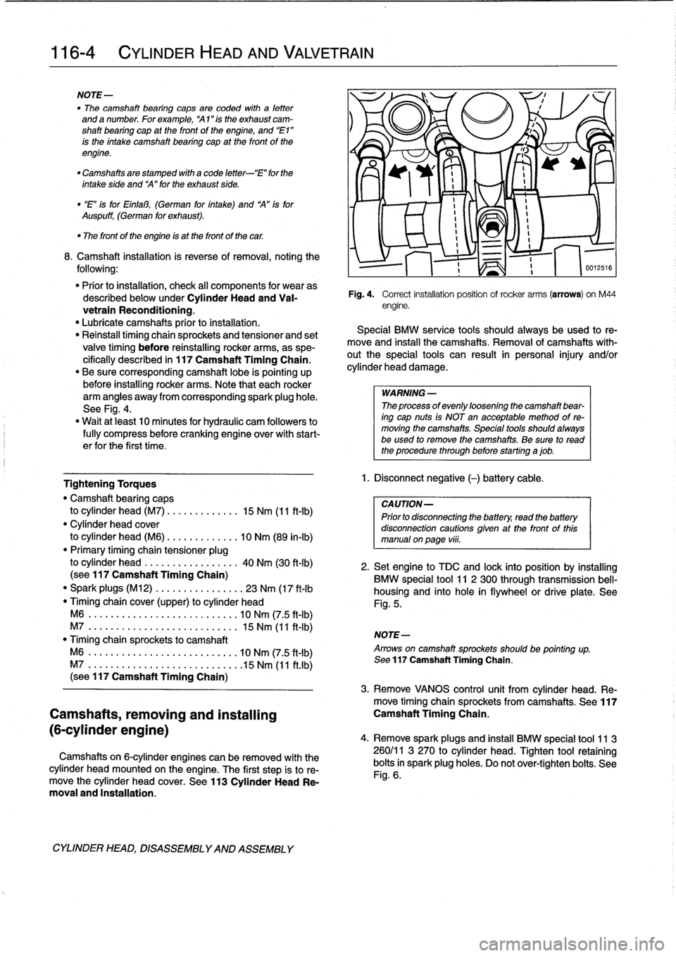
Fig
.
4
.
Correct
installation
position
ofrocker
arms
(arrows)
on
M44
engine
.
Special
BMW
service
tools
should
always
be
used
to
re-
move
and
instan
the
camshafts
.
Removal
of
camshafts
with-
outthe
special
tools
can
result
in
personal
injury
and/or
cylinder
head
damage
.
WARNING
-
The
processof
evenly
loosening
the
camshaft
bear-
ing
cap
nuts
is
NOT
en
acceptable
method
of
re-
moving
the
camshafts
.
Special
tools
shouldalways
be
used
lo
remove
the
camshafts
.
Be
sure
to
read
the
procedure
through
before
starting
ajob
.
1
.
Disconnect
negative
(-)
battery
cable
.
CAUTION-
Prior
to
disconnectiog
the
battery,
read
the
battery
disconnection
cautions
given
at
the
front
of
this
manual
onpaga
viii
.
516
2
.
Setengine
to
TDC
and
lock
into
position
by
installing
BMW
special
tool
11
2
300
through
transmission
bell-
housing
and
into
hole
in
flywheel
or
drive
platea
See
Fig
.
5
.
NOTE-
Arrows
on
camshaft
sprockets
shouldbe
pointing
up
.
Sea
117
Camshaft
Timing
Chain
.
3
.
Remove
VANOS
control
unit
from
cylinder
head
.
Re-
move
timing
chainsprockets
from
camshafts
.
See117
Camshaft
Timing
Chain
.
4
.
Remove
sparkplugs
and
insta¡¡
BMW
special
tool
11
3
260/11
3
270
to
cylinder
head
.
Tighten
tool
retaining
bolts
in
spark
plug
holes
.
Do
not
ovar-tighten
bolts
.
See
Fig
.
6
.
Page 125 of 759

GENERAL
.
........
.
...........
.
.
.
.
.
.
.
120-1
Camshaft
Position
(CMP)
Sensor
....
.
.
.
...
120-6
Disabling
Ignition
System
.
.
.
.
.....
.
.
.
.
.
.
.
120-2
Camshaft
position
(CMP)
sensor,
replacing
Warnings
and
Cautions
.
.
.
.
.
.
.....
.
.
.
.
.
.
.
120-2
(4-cylinder
engine)
..
.
.
.
.
.
.
.
.
.
.
.
.
.
.
.
...
120-6
Camshaft
position
(CMP)
sensor,
replacing
IGNITION
SYSTEM
DIAGNOSTICS
.
.
.
.
.
.
120-3
(6-cylinder
engine)
..
.
.
.
.
.
.
.
.
.
.
.
.
.
.
.
.
.
.
120-7
Basic
Troubleshooting
Principles
...
.
.
.
.
.
.
.
120-3
Knock
sensors,
replacing
.
.
...
.
.
.
.
.
.
.
.
.
.
.
.
120-7
Ignition
Firing
Order
.....
.
...
.
.
.
.....
.
.
.
.120-7
IGNITION
SYSTEM
SERVICE
.
.........
.
120-3
Checking
for
Spark
..
.
.
.
.
.
.
.
.
.
.......
.
.
.
120-3
Ignition
coil,
testing
and
replacing
(4-cylinder
engine)
.
.
.
.
.
.
.
.
.
.
.........
.
120-3
Ignition
coil,
testing
and
replacing
(6-cylinder
engine)
.........
.
..........
120-4
Crankshaft
Positionlrpm
Sensor
.......
.
...
120-5
Crankshaft
position/rpm
sensor,
testing
and
replacing
(front
mounted)
.........
.
.
.
.
.
.
120-6
Crankshaft
position/rpm
sensor,replacing
(rear
mounted)
.....
.
.....
.
.....
.
.
.
.
.
.
120-6
GENERAL
Troubleshooting
and
testing
of
the
engine
management
system
should
be
carried
out
using
the
BMW
specialized
ser
This
repair
group
covers
repair
andcomponent
replace-
vice
tester
(scan
tool)
.
ment
information
for
the
ignition
system
.
All
engines
use
a
distributorless
ignition
system
with
indívid-
ual
ignitioncoils
for
each
cylinder
.
There
is
no
distributor
cap
NOTE-
or
ignition
rotor
.
Each
coil
can
be
selectively
controlled
by
the
"
Spark
plug
replacement
is
covered
in
020
Mainte-
engine
control
module
on
a
cylinder-by-cylinder
basis
.
On
later
nance
Program
.
systems,
knock
sensors
are
used
to
monitor
and
control
igni-
"
For
fuel
related
troubleshooting
and
testing,
see
130
tion
knock
(ping)
and
adjusttiming
accordingly
.
Fuel
lnjection
.
Ignition
timing
is
electronically
controlled
and
not
adjust-
All
engines
covered
by
this
manual
use
an
advanced
en-
able
.
The
engine
control
module
(ECM)
usesengine
load,
en-
gine
management
system
.
The
engine
management
system
gine
speed,
coolant
temperature,
and
intake
air
temperature
incorporates
on-board
diagnostics,
fuel
injection,
ignition
and
as
the
basic
inputs
for
timing
control
.
Knock
detection
is
also
other
advanced
engine
control
functions
.
an
input
to
the
control
module,
where
applicable
.
Table
a
.
Engine
Management
System
Variants
Engine
code
1
System
4-cylinder
M42
(1.8
I)
Bosch
DME
Ml
.7
M44
(1
.9
I)
Bosch
DME
M5
.2
(OBD
II)
6-cylinder
M50
1992
(2.5
I)
Bosch
DME
M8
.1
1993-1995
(2
.5
I)
Bosch
DME
M33
.1
M52
1996-1998
(2.8
I)
Siemens
MS
41
.1
(OBD
II)
1998
(2
.5
I)
Siemens
MS
41
.1
(013D
11)
S50US
(3.0
I)
Bosch
DME
M3
.3.1
S52US
(3.2
I)
Siemens
MS
41
.1
(OBD
II)
120
Ignition
System
IGNITION
SYSTEM
120-1
IGNITION
SYSTEM
SCHEMATICS
...
.
.
.
.120-7
TABLES
a
.
Engine
Management
System
Variants
......
120-1
b
.
Ignition
Coil
Resistance
(M42
engine)
......
120-4
c
.
Ignition
Coil
Resistance
(M44
engine)
......
120-4
d
.
Ignition
Coil
Resistance
(6-cylinder
engine)
..
.
.
.
.
.
.
.
.
.
.
.
.....
.
..
120-5
NOTE-
All
engines
coveredby
this
manual,
with
theexception
of
the
1992
M50,
incorporate
knocksensors
as
part
of
the
engine
management
system
.
The
initial
ignition
point
is
determined
by
the
crankshaft
po-
sition/rpm
sensor
during
cranking
.
Once
the
engine
is
run-
ning,
timing
is
continually
adjusted
based
on
operating
conditions
.
A
characteristic
ignition
map
is
shown
in
Fig
.
1
.
A
map
similar
to
the
one
shown
is
digitally
stored
in
the
engine
control
module
.
GENERAL