lights BMW 325i 1996 E36 Workshop Manual
[x] Cancel search | Manufacturer: BMW, Model Year: 1996, Model line: 325i, Model: BMW 325i 1996 E36Pages: 759
Page 9 of 759
GENERAL
FUNDAMENTALS
FORTHE
DO-IT
YOURSELF
OWNER
010-1
010
Fundamentals
for
the
Do-lt-Yourself
Owner
GENERAL
.......
.
.
.
......
.
.........
.
.
.010-1
TOOLS
.
.
...
.
............
.
............
010-8
Basic
Tool
Requirements
......
.
.
.
.
.
.
.
.
.
.
010-8
HOW
TO
USE
THIS
MANUAL
.
...
.
...
.
.
.
010-2
JackStands
.
.
.
.
.
.
.
.
.
.......
.
.
.
.
...
.
.
010-9
Warnings,
Cautions
and
Notes
.........
.
.
.
010-2
Oil
Change
Equipment
.
....
.
......
.
...
.
.
010-9
GETTING
STARTED
.
.......
.
.
.
.
.
......
.010-2
Torque
Wrench
....
.
.
.
....
.
..
.
.
.
.
.
...
.
010-10
Feeler
Gauges
.
...
.
.
.
.......
.
.
.
.
.
.
.
.
.
010-10
Safety
....
.
.....
.....
.
.
.
.
.
...
.
.
.
.
.
.
.
010-2
Digital
Multimeter
.
.
.
.
.
.....
.
.
.
.
.
.
.
.
.
.
.
010-10
Lífting
the
Car
...........
.
.
.
.
.
.
.
.
.
...
.
.
.
010-3
gMW
Special
Tools
...
.
....
..
.....
.
...
.
010-11
Raising
car
safely
...
..
...
.
...
.
.....
.
...
010-3
Working
under
car
safely
...
..
....
.
.....
.
...
010-4
EMERGENCIES
.
.
.
.
.
.
.....
.
.
.
.
.
.
.
...
.
010-11
ADVICE
FOR
THE
BEGINNER
.......
.
.
.
010-4
Changing
a
Tire
.
.
.
.
.
.
....
..
.
.
.
.
.
.
.
.
.
.010-11
Car
Will
Not
Start
....
.
....
.
.
.
........
.010-11
Planning
Ahead
....
.
...........
.
....
.
.
.
010-4
Jump
Starting
Car
..
.
.
.
....
.
...........
010-12
Cleanliness
.
.
.
.
.
.
.
..
....
.
.
.
.
.
.
.
.
.
.
.
.
.
.
.
010-4
Overheating
.
.....
.
.
.
.........
.
.
.
...
.
010-12
Non-reusable
Fasteners
...
.
.
.
.
.
.
.
.
.
.
.
.
.
.
.
010-5
Low
Oil
Pressure
...
...
.
.
...
.
.
.
..
...
....
010-13
Tightening
Fasteners
.....
.
.
.
...
.
.
.
.
.
.
.
.
.
010-5
Brake
Fluid
Level
.
.
.....
.
.
.
.
.
...
.
.....
010-13
Gaskets
and
Seals
.......
.
.
.
...
.
.....
.
.
.
010-5
Check
Engine
Warning
Light
.
.
.
...
.
.....
010-13
Electrical
Testing
.
.
.
.
.
.
.
.
.
.
.
.
.
.
.
.
.
...
.
.
.
010-6
pim
Lights
.....
.
..
.
.
.
....
.
.
.
.........
010-13Wire
Repairs
.
.
.
.
.
.
.
.
.
.
...
.
.
.
.
.
.
.
......
010-6
Towíng
.
.
...
.
.
.
.
.
.
.
.
.
.
.
...
.
.
.
.
.
...
.
.010-13
BUYINGPARTS
.
.
.
.....
.
.
.
...
.
.
.
...
.
.
.
010-6
Spare
Parts
Kit
.
.
.
.
.
.
.......
.
.
.
.
.
.....
010-14
Genuine
BMW
Parts
.
.
.
.
.
.
.
.
.
.
.
.
.
.
......
010-6
Non-returnable
Parts
.
.
.
.
.
.
.
.
.
.
.
.
.
.
......
010-7
TABLES
Information
You
Need
to
Know
.
.
.
.
.
.
......
010-7
a
.
General
Bolt
Tightening
Torques
SERVICE
.
.
.
.
.
.
.
.
.
.
.
.
.......
.
..........
010-7
Although
the
BMW
is
a
sophisticated
and
complex
machine,
basic
maintenance
can
be
accomplished
byan
interested
own-
er
with
mechanical
skills
and
the
right
information
.
Most
of
the
preventive
maintenance
that
is
required
in
the
lifetime
of
theav-
erage
BMW
is
weil
within
the
capabilitiesof
the
do-it-yourseifer
.
WARNING
-
Do
not
use
this
manual
unless
you
are
familiar
with
basicautomotive
repair
procedures
and
sale
work-
shop
practices
.
This
manual
illustrates
the
work-
shop
procedures
required
for
most
service
work
;it
is
not
a
substitute
for
full
and
up-to-date
information
from
the
vehicle
manufacturer
or
for
proper
training
asan
automotive
technician
.
Note
that
it
is
not
pos-
sible
for
us
to
anticipate
al¡
of
the
ways
orconditions
underwhich
vehicles
may
be
serviced
or
to
provide
cautions
as
to
all
of
the
possible
hazards
that
may
result
'
in
Nm
(max
.
permissible)
.
..
.
...
............
.
010-5
WARNING
-
Your
common
sense
and
good
judgment
are
crucial
tosale
and
successful
service
work
.
Read
proce-
dures
through
before
starting
them
.
Thinkabout
whether
the
condition
ofyour
car,
your
leve¡
of
me-
chanical
skill,
or
your
leve¡
of
reading
comprehen-
sion
might
result
in
orcontribute
in
some
way
to
an
occurrence
that
might
cause
you
injury
damage
your
car,
or
result
in
an
unsafe
repair
.
lf
you
havedoubts
for
these
or
other
reasonsaboutyour
abilíty
to
perform
sale
repair
work
onyour
car,
have
the
work
done
at
an
authorized
BMW
dealer
or
other
qualified
shop
.
This
section
of
the
manual
is
intended
to
helpthe
beginner
get
started
.
To
begin
with
there
is
a
discussion
on
How
To
Use
This
Manual
.
Tips
on
mechanicas
skills
and
workshop
practic-
es
that
can
help
the
beginner
do
a
faster
and
more
thorough
job
can
be
foundunderGettingStarted
.
The
basic
tools
needed
to
do
most
of
the
procedures
in
this
manual
are
foundunder
Tools
.
The
section
ends
with
a
quick
reference
guide
to
Emer-
gencies,
including
basictroubleshooting
and
information
on
how
to
gauge
the
seriousness
of
a
problem
.
GENERAL
Page 20 of 759
010-12
FUNDAMENTALSFOR
THE
DO-IT
YOURSELF
OWNER
Jump
Starting
Car
Cars
with
discharged
or
dead
batteries
can
be
jump-started
using
the
good
battery
from
another
car
.
When
jump-starting
the
engine,
always
note
the
following
warnings
.
WARNING
-
"
Battery
acid
(electrolyte)
can
cause
severe
burns,
and
will
damage
the
car
and
clothing
.
lf
electrolyte
is
spilled,
wash
the
surface
with
large
quantities
of
water
.
lfit
gets
finto
eyes,
flush
them
with
water
for
severa¡
minutes
and
cal¡
a
doctor
.
"
Batteries
produce
explosive
and
noxious
gas-
ses
.
Keep
sparks
and
flames
away
.
Do
not
smoke
near
batteries
.
"
Do
not
jump-start
the
engine
if
you
suspect
that
the
battery
is
frozen
.
Trapped
gas
may
explode
.
Allow
the
battery
to
thaw
first
.
"
Do
not
quick-charge
the
battery
(for
boost
start-
ing)for
longer
than
one
minute,
and
donot
ex-
ceed
15
volts
at
the
battery
with
the
boosting
cables
attached
.
Wait
at
least
one
minutebefore
boosting
the
battery
a
second
time
.
"
Some
electrical
system
'comfort"
features
may
not
function
correctly
once
battery
power
is
restored
.
For
example,
the
front
window
one-touch-up
func-
tion
may
be
disabled
.
Some
electrical
systems
will
need
to
be
reinitialized
Consult
the
appropriate
re-
pairgroup
formore
specific
information
.
1
.
Place
cars
close
together,
but
do
not
allow
them
to'touch
each
other
.
Turn
off
the
engine
of
thecar
with
the
good
battery
.
2
.
Connect
oneend
of
the
positive
(+)
cable
to
the
positive
(+)
post
of
the
good
battery
.
Remove
the
coverfromthe
positive
(B+)
junction
post
in
the
engine
compartment
of
the
dead
car
and
connect
the
other
end
of
the
posi-
tive
(+)
cable
to
the
junction
post
.
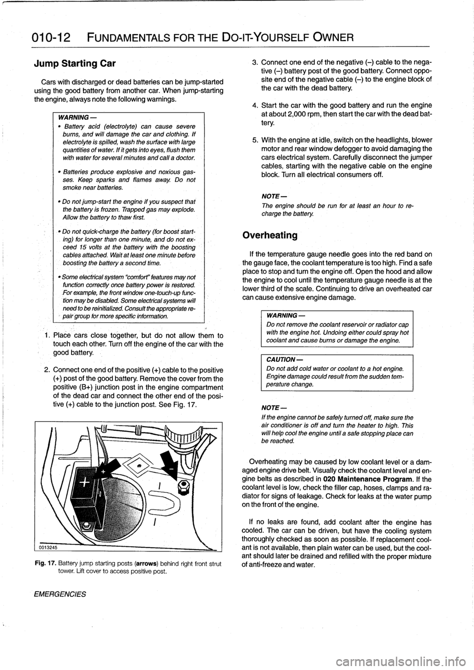
See
Fig
.
17
.
EMERGENCIES
3
.
Connect
one
end
of
the
negative
(-)
cable
to
the
nega-
tive
(-)
battery
post
of
the
good
battery
.
Connect
oppo-
site
end
of
the
negative
cable
(-)
to
the
engine
block
of
thecar
with
the
dead
battery
.
4
.
Start
thecar
with
the
good
battery
and
runthe
engine
at
about2,000
rpm,
then
start
the
car
with
the
dead
bat-
tery
.
5
.
With
the
engine
at
¡dle,
switch
on
the
headlights,
blower
motor
and
rear
window
defogger
to
avoid
damaging
the
cars
electrical
system
.
Carefully
disconnect
the
jumper
cables,
starting
with
the
negative
cable
on
the
engine
block
.
Turn
all
electrical
consumers
off
.
NOTE-
The
engineshould
be
run
for
at
least
an
hour
to
re-
charge
the
battery
.
Overheating
lf
the
temperature
gauge
needle
goes
into
the
red
band
on
the
gauge
face,
the
coolant
temperature
is
too
high
.
Find
a
safe
place
to
stop
and
turn
the
engine
off
.
Open
the
hood
and
allow
the
engine
to
cool
until
the
temperature
gauge
needle
is
at
the
lower
thirdof
the
scale
.
Continuing
to
drive
an
overheated
car
can
cause
extensive
engine
damage
.
WARNING
-
Do
not
remove
the
coolant
reservoir
or
radíator
cap
with
the
engine
hot
.
Undoing
either
couldspray
hot
coolant
and
cause
burns
or
damage
the
engine
.
CAUTION-
Do
not
add
cold
water
or
coolant
to
a
hot
engine
.
Engine
damage
could
result
from
the
sudden
tem-
perature
change
.
NOTE-
If
the
enginecannot
be
safely
tumed
off,
make
sure
the
air
condifioner
isoff
and
turn
the
heater
to
high
.
This
will
helo
cool
the
engine
until
a
salestopping
place
canbe
reached
.
Overheating
may
be
caused
bylow
coolant
leve¡
or
a
dam-aged
engine
drive
belt
.
Visually
check
the
coolant
leve¡
and
en-
gine
belts
as
described
in
020
Maintenance
Program
.
lf
the
coolant
leve¡
is
low,
check
the
filler
cap,hoses,
clamps
and
ra-
diator
for
signs
of
leakage
.
Check
for
leaks
at
the
water
pump
on
the
frontof
theengine
.
lf
no
leaks
are
found,
add
coolant
after
the
engine
has
cooled
.
The
carcan
be
driven,
but
have
the
cooling
system
thoroughly
checked
assoonas
possible
.
lf
replacement
cool
0013245
-
ant
is
not
available,
then
plain
water
canbe
used,
butthe
cool-
antshould
later
be
drained
and
refilled
with
theproper
mixture
Fig
.
17
.
Battery
jump
starting
posts
(arrows)
behind
right
frontstrut
of
anti-freeze
and
water
.
tower
.
Lift
cover
to
access
positive
post
.
Page 21 of 759
If
steam
is
coming
from
the
engine
compartment
thenthere
is
With
the
engine
and
ignition
off,
check
for
loose
or
corroded
most
likely
a
burst
coolant
hose
or
a
large
leak
in
the
cooling
battery
cables
or
wires
at
the
battery
or
thealtemator
.
Discon-
system
.
To
find
the
leak,
look
for
signs
of
coolant
leakage
on
necting,
cleaning,
and
reinstalling
corroded
wires
and
connec-
hoses,
at
hose
connections,
or
on
the
radiator
.
Let
theengine
tors
may
solve
the
problem
.
Also
check
drive
belt
tension
as
cool
thoroughly,
then
add
coolant
or
water
to
fill
the
system
and
described
in
020
Maintenance
Program
.
start
the
engine
.
If
a
great
deal
of
water
or
coolant
flows
out
of
the
hole,
then
thecarshouldnot
be
driven
until
repairs
are
made
.
lf
there
is
slight
seepage,
then
it
may
be
possible
to
drive
TOWi
ng
a
short
distance,
adding
coolant
as
needed
.
The
cars
covered
by
this
manual
should
be
towed
witha
tow
truck
using
wheel
lift
or
flat
bed
equipment
.
Do
not
tow
thecar
on
all
four
wheels
except
for
very
short
distances
to
move
it
to
a
safe
place
.
If
thered
engine
oil
pressure
warning
light
illuminates,
imme-
diately
stop
thecar
and
turn
off
the
engine
.
Have
the
vehicle
A
towing
eye
is
provided
in
the
luggage
compartment
tool
kit
.
flat-bedded
or
towed
to
an
authorized
service
center
and
have
The
towing
eye
can
be
screwed
into
the
front
or
rear
bumper
.
the
engine
oil
pressure
checked
.
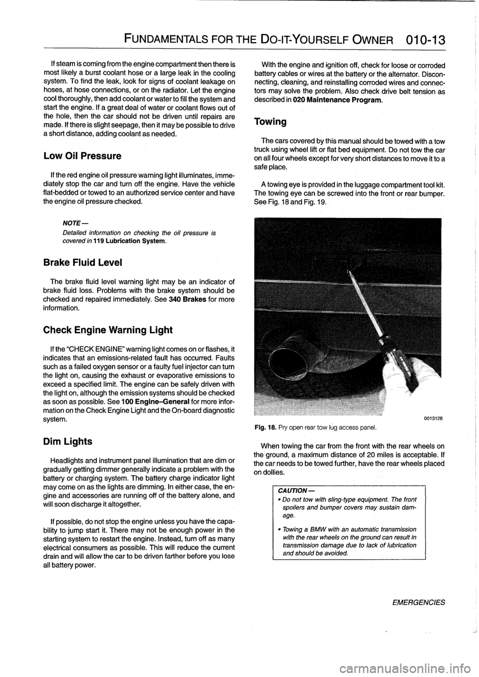
See
Fig
.
18
and
Fig
.
19
.
Low
Oil
Pressure
NOTE-
Detafed
information
on
checking
the
oil
pressure
is
covered
ín
119
Lubrication
System
.
Brake
Fluid
Leve¡
The
brake
fluid
leve¡
warning
light
may
bean
indicator
of
brake
fluid
loss
.
Problems
with
the
brakesystem
should
be
checked
and
repaired
immediately
.
See
340Brakes
for
more
information
.
Check
Engine
Warning
Light
Dim
Lights
FUNDAMENTALS
FOR
THE
DO-IT
YOURSELF
OWNER
010-13
If
the
"CHECK
ENGI
NE"
warning
light
comes
on
or
flashes,
it
indicates
that
an
emissions-related
fault
has
occurred
.
Faults
suchas
a
failed
oxygen
sensor
or
a
faultyfuelinjector
can
tum
the
light
on,
causing
the
exhaust
or
evaporative
emissions
to
exceed
a
specified
limit
.
The
engine
can
be
safely
driven
with
the
light
on,
although
the
emission
systems
should
be
checked
assoonas
possible
.
See
100
Engine-General
for
more
infor-
mation
on
the
Check
Engine
Light
and
the
On-board
diagnostic
system
.
Headlights
and
instrument
panel
illuminationthat
are
dim
or
gradually
getting
dimmer
generally
indicate
a
problem
with
the
battery
or
charging
system
.
The
battery
charge
indicator
light
may
come
on
as
the
lights
are
dimming
.
In
either
case,
theen-
gine
and
accessories
are
running
off
of
the
battery
alone,
and
will
soon
discharge
it
altogether
.
If
possible,
do
not
stop
the
engine
unless
you
have
the
capa-
bility
to
jump
start
¡t
.
There
may
not
be
enough
power
in
the
starting
system
torestart
the
engine
.
Instead,turn
off
as
many
electrical
consumers
as
possible
.
This
will
reduce
the
current
drain
and
will
allow
thecar
to
be
driven
farther
before
you
lose
all
battery
power
.
Fig
.
18
.
Pry
open
rear
tow
lúg
access
panel
.
When
towingthecar
from
the
front
with
the
rear
wheelson
the
ground,
a
maximum
distance
of
20
miles
is
acceptable
.
If
thecar
needs
to
be
towed
further,
have
the
rear
wheels
placed
on
dollies
.
CA
UTION-
"
Do
not
tow
with
sling-type
equipment
The
front
spoilers
andbumper
covers
may
sustain
dam-
age
.
"
Towínga
BMW
with
an
automatic
transmission
with
the
rear
wheelson
the
ground
can
resuft
in
transmission
damage
due
to
lackof
lubrication
and
should
be
avoided
.
0013128
EMERGENCIES
Page 24 of 759
020-2
MAINTENANCE
PROGRAM
GENERAL
The
information
given
in
this
repair
group
includes
the
routine
checks
and
maintenance
steps
that
are
both
required
by
BMW
under
the
terms
of
the
vehicle
warranty
protection
and
recom-
mended
by
BMW
to
ensure
long
and
reliable
vehicle
operation
.
GENERAL
NOTE-
Aside
from
keeping
yourcar
in
the
bestpossible
condi-
tion,
proper
maintenance
plays
a
role
in
maintaining
full
protection
under
BMWs
new-car
warranty
coverage
.
If
in
doubtabout
the
terms
and
conditions
of
yourcark
warranty,
an
authorized
BMW
dealer
should
be
able
to
explain
them
.
NOTE-
BMW
is
constantly
updating
their
recommended
main-
tenance
procedures
and
requirements
.
The
informa-
tion
contained
here
is
as
accurate
as
possible
at
the
time
of
publication
.
If
hhere
is
any
doubt
aboutwhat
pro-
cedures
apply
to
a
specific
model
or
model
year,
or
what
intervals
should
be
followed,
remember
that
an
authorized
BMW
dealer
has
the
latest
information
on
factory-recommended
maintenance
.
BMW
Service
Indicator
The
BMW
Service
Indicator
notifies
the
driver
when
mainte-
nance
is
required
.
The
service
indicator
consístsof
multiple
light
emitting
diodes
(lEDs)-typically
five
green,
one
yellow,
andone
red-as
well
as
OIL
SERVICE
and
INSPECTION
indi-
cators
.
When
the
ignition
is
tumed
on,the
green
LEDs
come
on
.
They
go
out
when
the
engine
is
started
.
After
the
Service
Indi-
cator
is
reset,
al¡
green
LEDs
will
be
illuminatedwith
the
keyon
.
As
thecar
is
driven
in
normal
use,
fewer
and
fewer
green
LEDs
will
be
illuminated
before
start-up,indicating
that
the
next
main-
tenance
interval
is
approaching
.
When
thecar
has
accumulated
sufficient
use
to
require
the
next
maintenance
interval,
the
yellow
LED
will
come
on
along
with
either
the
OIL
SERVICE
indicator
or
the
INSPECTION
in-
dicator
.
These
LEDs
will
stay
on
after
the
engine
is
started
.
If
maintenance
service
is
delayed,
thered
LED
will
also
illuminate
as
a
reminder
that
maintenance
service
is
overdue
.
An
OIL
SERVICE
interval
will
alwaysbe
followed
by
an
IN-
SPECTION
interval,
which
will
then
be
followed
byan
OIL
SER-VICE
interval,
andsoon
.
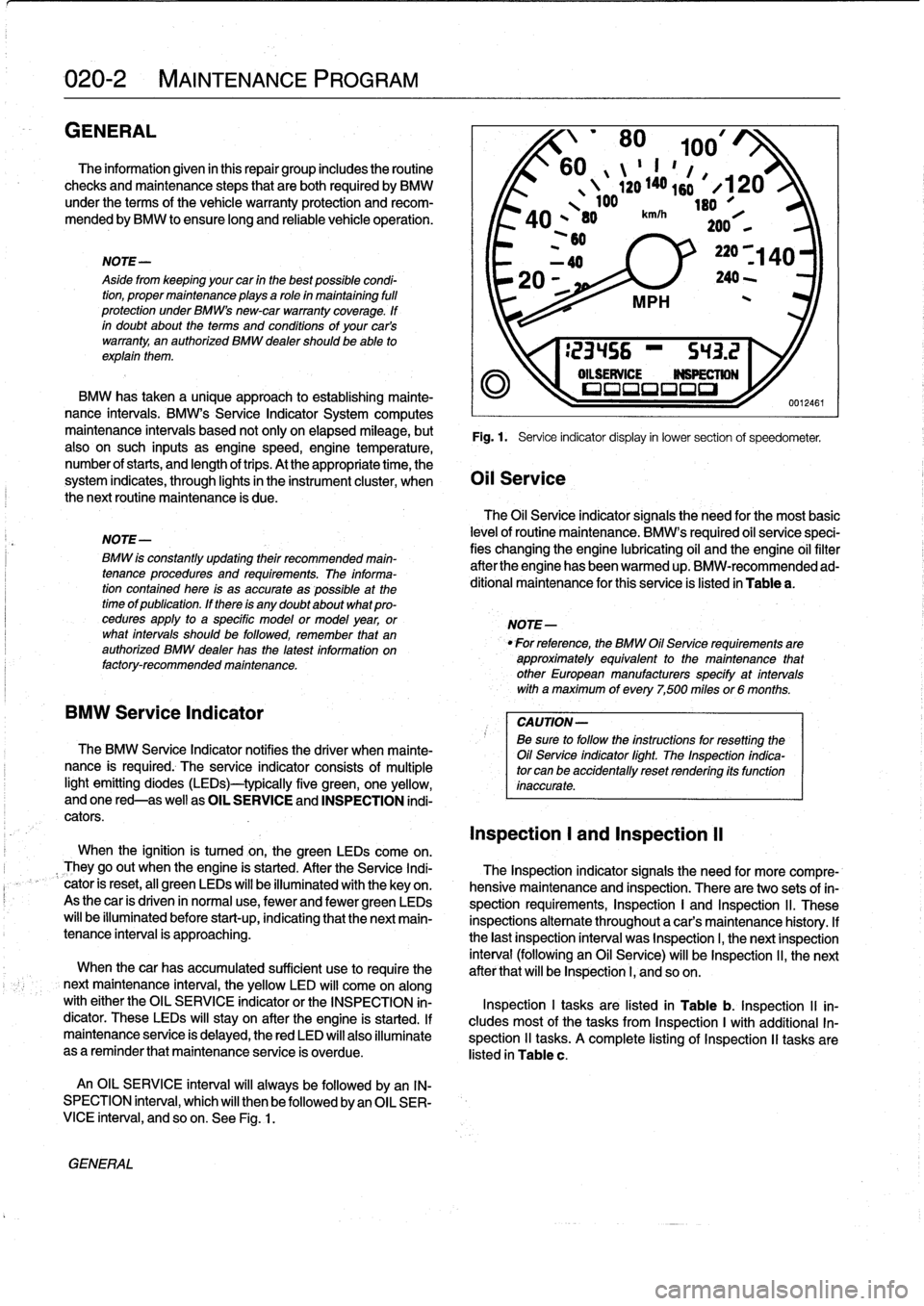
See
Fig
.
1
.
'
80
100/
60
II
"
1
,
ló
1
,
4
`20
140s
#
X120
100
leo
A
O
,
80
km/h`F
*101
200
,
,
~60
BMW
has
taken
a
unique
approach
to
establishing
mainte-
nance
intervals
.
BMW's
Service
Indicator
System
computes
maintenance
intervais
based
not
only
on
elapsed
mileage,
but
Fig
.
1
.
Service
indicator
display
in
lower
section
of
speedometer
.
also
on
such
inputs
as
enginespeed,engine
temperature,
number
of
starts,
and
length
oftrips
.
At
the
appropriate
time,
the
system
indicates,
through
lights
in
the
instrument
cluster,
when
Oil
Service
the
next
routine
maintenance
is
due
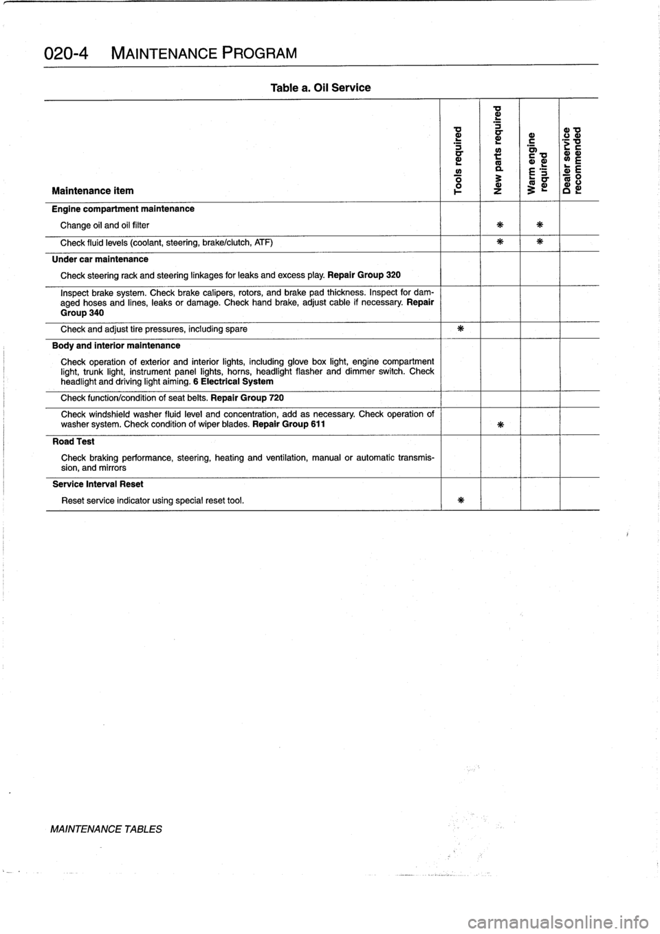
.
The
Oil
Service
indicator
signals
the
need
for
the
most
basic
levelof
routine
maintenance
.
BMW's
required
oil
service
speci-
fies
changing
the
engine
lubricating
oil
and
the
engine
oil
filter
after
the
engine
has
been
warmed
up
.
BMW-recommended
ad-
ditional
maintenance
for
this
service
is
listed
in
Table
a
.
NOTE-
For
reference,
the
BMW
Oil
Service
requirements
are
approximately
equivalent
to
the
maintenance
that
other
European
manufacturers
specify
at
intervals
with
a
maximum
of
every
7,500
miles
or6
months
.
CAUTION-
Be
sure
to
follow
the
ínstructions
forresetting
the
Oil
Service
indicator
fight
.
The
Inspection
indica-
tor
can
be
accidentally
reset
rendering
its
function
inaccurate
.
Inspection
l
and
Inspection
II
The
Inspection
indicator
signals
the
need
for
more
compre-
hensive
maintenance
and
Inspection
.
There
are
two
sets
of
in-
spection
requirements,
Inspection
I
and
Inspection
ll
.
These
inspections
alternate
throughout
a
car's
maintenance
history
.
If
the
last
Inspection
interval
was
Inspection
I,
the
next
Inspection
interval
(following
an
Oil
Service)
will
be
Inspection
ll,
the
next
after
that
will
be
Inspection
I,
and
so
on
.
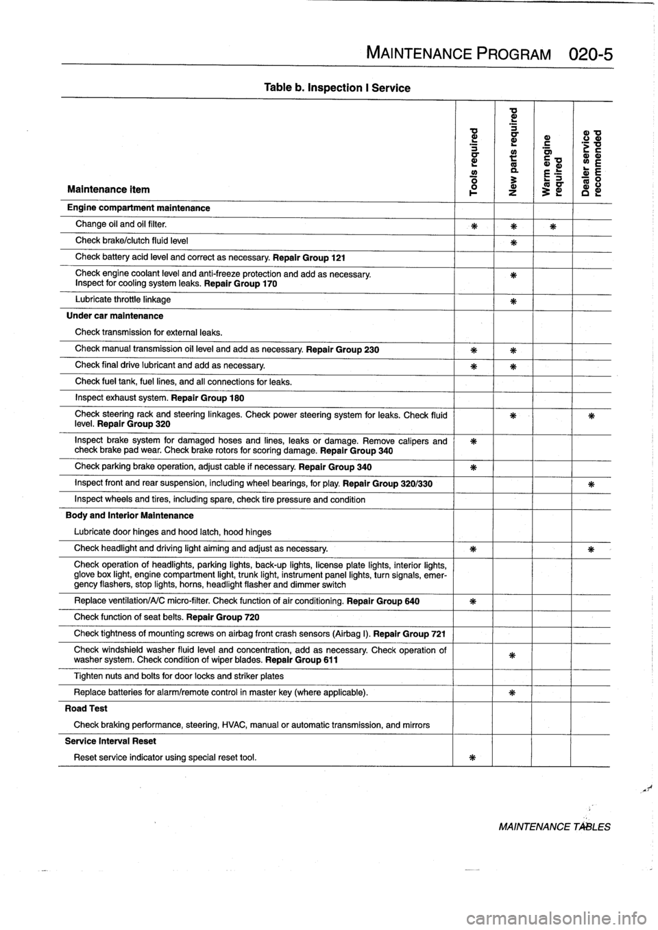
Inspection
I
tasks
are
listed
in
Table
b
.
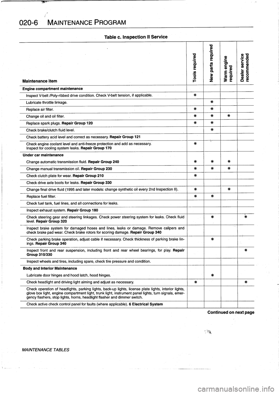
Inspection
II
in-
cludes
most
of
the
tasks
from
Inspection
I
with
additional
In-
spection
11
tasks
.
A
complete
listing
of
Inspection
II
tasks
are
listed
in
Table
c
.
Page 26 of 759
020-
4
MAINTENANCE
PROGRAM
L
~
~
c
.c
a
a>
mL
~
~L
L
w
a
£
'S
d
E
Maintenance
ítem
z
3
c
Engine
compartment
maintenance
Change
oil
and
oil
filter
Check
fluid
levels
(coolant,steering,
brake/clutch,
ATF)
Under
car
maintenance
Check
steeringrack
and
steeringlinkages
for
leaks
andexcess
play
.
Repair
Group
320
Inspect
brake
system
.
Check
brake
calipers,
rotors,
and
brake
pad
thíckness
.
Inspect
for
dam-
aged
hoses
and
lines,
leaks
or
damage
.
Check
hand
brake,adjust
cable
if
necessary
.
Repair
Group
340
Check
and
adjust
tire
pressures,
including
spare
Body
and
interior
maintenance
Check
operation
of
exterior
and
interior
lights,
including
glove
box
light,
engine
compartment
light,
trunk
light,
instrument
panel
lights,
horns,
headlight
flasher
anddimmer
switch
.
Check
headlight
and
driving
light
aiming
.
6
Electrical
System
Check
function/condition
of
seat
belts
.
Repair
Group
720
Check
windshield
washer
fluid
level
and
concentration,
add
as
necessary
.
Check
operation
of
washer
system
.
Check
condition
of
wiper
blades
.
Repair
Group
611
Road
Test
Check
braking
performance,
steering,
heating
and
ventilation,
manual
or
automatic
transmis-
sion,
and
mirrors
Service
Interval
Reset
Reset
service
indicator
using
specialreset
tool
.
MAINTENANCE
TABLES
Table
a
.
Oil
Service
Page 27 of 759
Table
b
.
Inspection
I
Service
MAINTENANCE
PROGRAM
020-5
ad
d
d
ID
a
r
c
d
a~
;v
a
:
Q~
wE
y
a
r
E
R
:
L-
0
Maintenance
ítem
1
z
3
~
c
d
Engine
compartment
maintenance
Change
oil
and
oil
filter
.
Check
brake/clutch
fluid
leve¡
Check
battery
acid
leve¡
and
correct
asnecessary
.
Repair
Group
121
Check
engine
coolant
level
and
anti-freeze
protection
and
addasnecessary
.
Inspect
for
cooling
system
leaks
.
Repair
Group
170
Lubricate
throttie
linkage
Under
car
maintenance
Check
transmission
for
externa¡
leaks
.
Check
manual
transmission
oil
leve¡
andadd
asnecessary
.
Repair
Group
230
Check
final
drive
lubricant
and
addasnecessary
.
Check
fue¡
tank,
fuel
lines,
and
all
connections
for
leaks
.
Inspect
exhaust
system
.
Repair
Group
180
Check
steeringrack
and
steeringlinkages
.
Check
power
steering
system
for
leaks
.
Check
(luid
leve¡
.
Repair
Group
320
Inspect
brake
system
for
damaged
hoses
and
fines,
leaks
or
damage
.
Remove
calipers
and
check
brake
pad
wear
.
Check
brake
rotors
for
scoring
damage
.
Repair
Group
340
Check
parking
brake
operation,
adjust
cable
if
necessary
Repair
Group
340
Inspect
front
and
rear
suspension,
including
wheel
bearings,
for
play
.
Repair
Group
320/330
Inspect
wheelsand
tires,
including
spare,
check
tire
pressure
and
condition
Body
and
Interior
Maintenance
Lubricate
door
hinges
and
hood
latch,
hood
hinges
Check
headlight
and
driving
light
aiming
and
adjust
as
necessary
.
Check
operation
of
headlights,
parking
lights,
back-up
fights,
licenseplate
lights,
interior
lights,
glove
box
light,
engine
compartment
light,
trunk
light,
instrument
panel
lights,
turnsignals,
emer-gency
flashers,
stop
fights,
horas,
headlight
flasher
and
dimmer
switch
Replace
ventilation/A/C
micro-filter
.
Check
functionof
air
conditioning
.
Repair
Group
640
Check
function
of
seat
belts
.
Repair
Group
720
Check
tightness
of
mountfng
screws
on
airbag
front
crash
sensors
(Airbag
I)
.
Repair
Group
721
Check
windshield
washer
fluid
leve¡
and
concentration,
add
as
necessary
Check
operation
of
washer
system
.
Check
condition
of
wiperblades
.
Repair
Group
611
Tighten
nuts
and
bolts
for
door
locks
and
striker
plates
Replace
batteries
for
alarm/remote
control
in
masterkey(where
applicable)
.
Road
Test
Check
braking
performance,
steering,
HVAC,
manual
or
automatic
transmission,
and
mirrors
Service
Interval
Reset
Reset
service
indicator
using
specialreset
tool
.
MAINTENANCE
TALES
Page 28 of 759
020-6
MAINTENANCE
PROGRAM
Group
310/330
Table
c
.
Inspection
II
Service
a
d
d
a
a>
0
d
a
r
.c
mm
L
m
y
L
E
ó
3
E
ó
Maintenance
ítem
l
o-
z
~
c
Engine
compartment
maintenance
Inspect
V-belt
/Poly-ribbeddrive
condition
.
Check
V-belt
tension,
if
applicable
.
Lubricate
throttle
linkage
.
Replace
air
filter
.
Change
oil
and
oil
filter
.
Replacespark
plugs
.
Repair
Group
120
Check
brake/clutch
fluid
leve¡
.
Check
battery
acid
leve¡
and
correct
asnecessary
.
Repair
Group
121
Check
engine
coolant
leve¡
and
anti-freeze
protection
and
add
asnecessary
.
Inspect
for
cooling
system
leaks
.
Repair
Group
170
Under
car
maintenance
Change
automatic
transmission
fluid
.
Repair
Group
240
Change
manual
transmission
oil
.
Repair
Group
230
Check
clutch
plate
for
wear
.
Repair
Group
210
Check
drive
axle
boots
for
leaks
.
Repair
Group
330
Change
final
drive
fluid
(1995
and
later
models
:
change
synthetic
oil
every
2nd
Inspection
II)
.
Replace
fuel
filter
.
Check
fuel
tank,
fuel
lines,
and
af
connections
for
leaks
.
Inspect
exhaust
system
.
Repair
Group
180
Check
steering
gear
and
steering
¡inkages
.
Check
power
steering
system
for
leaks
.
Check
fluidleve¡
.
Repair
Group
320
Inspect
brake
system
for
damaged
hoses
and
lines,
leaks
or
damage
.
Remove
calipers
and
check
brake
pad
wear
.
Check
brake
rotors
for
scoring
damage
.
Repair
Group
340
Check
parking
brake
operation,
adjust
cable
if
necessary
.
Check
thickness
of
parking
brake
lin-
ings
.
Repair
Group
340
Inspect
front
and
rear
suspension,
including
front
and
rear
wheel
bearings,
for
play
.
Repair
Inspect
wheels
and
tires,
including
spare,
check
tire
pressure
and
condition
.
Body
and
Interior
Maintenance
Lubricate
door
hinges
and
hood
latch,
hood
hinges
.
Check
headlight
and
driving
light
aiming
and
adjust
asnecessary
.
Check
operation
of
headlights,
parking
lights,
back-up
lights,
licenseplate
lights,
interior
lights,
glove
box
light,
engine
compartment
light,
trunk
light,
instrument
panel
lights,
turn
signals,
emer-gency
flashers,
stop
lights,
horns,
headlight
flasher
anddimmer
switch
.
Check
active
check
control
panel
forfauits
(where
applicable)
.
6
Electrical
System
MAINTENANCE
TABLES
Continued
on
next
page
Page 138 of 759
121-2
BATTERY,
STARTER,
ALTERNATOR
CHARGING
SYSTEM
TROUBLESHOOTING
Static
currentdraw,
checking
Charging
system
diagnostics
requires
special
test
equip-
ment
.
If
the
test
equipment
is
not
available,
charging
system
fault
diagnosis
can
be
performedby
an
authorized
BMW
deal-
eror
other
qualified
repair
shop
.
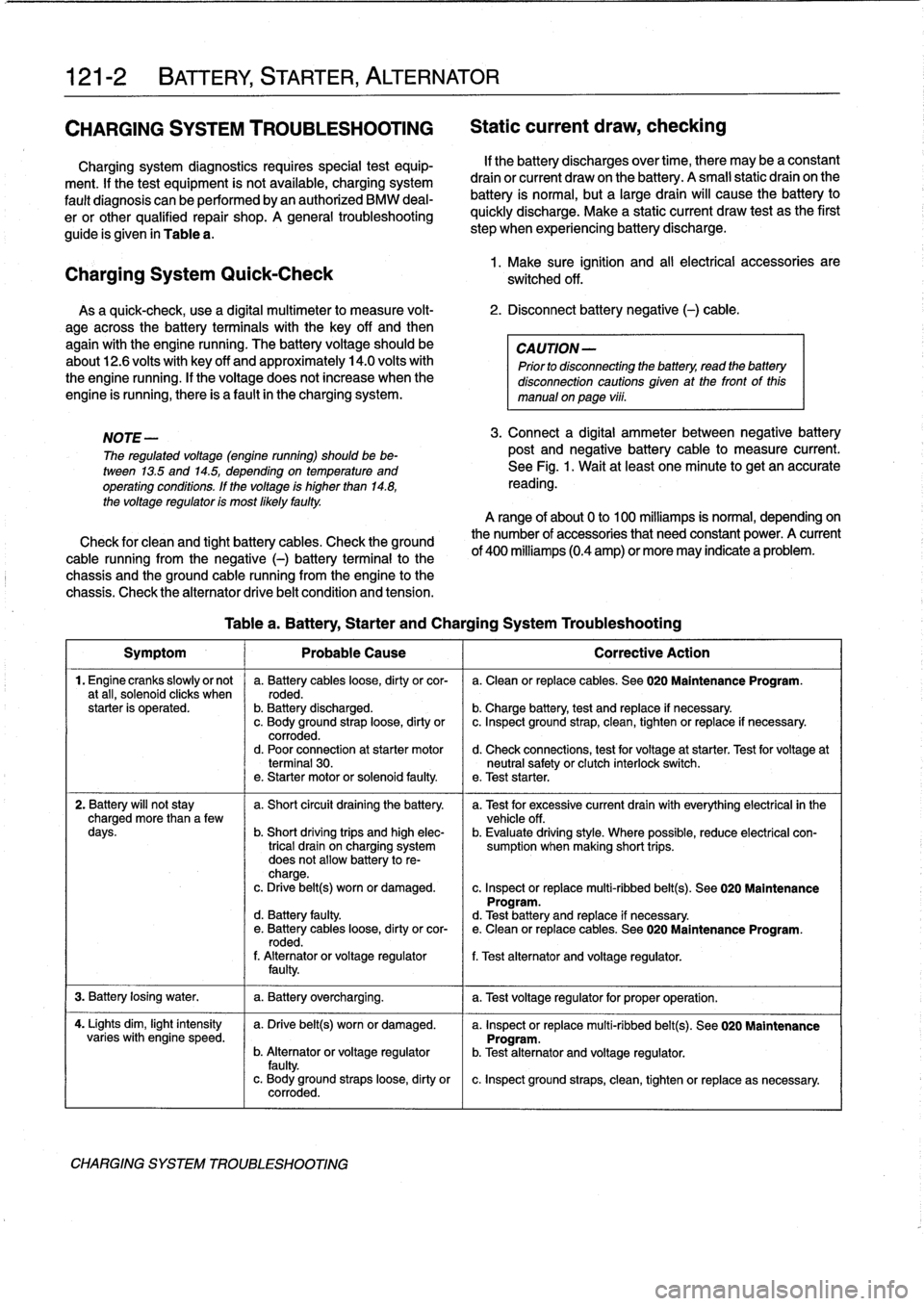
A
general
troubleshooting
guide
is
given
in
Table
a
.
Charging
System
Quick-Check
As
a
quick-check,
use
a
digital
multimeter
lo
measure
volt-
2
.
Disconnect
battery
negative
(-)
cable
.
age
across
the
battery
terminals
with
the
key
off
and
then
again
with
the
engine
running
.
The
battery
voltage
should
be
CAUTION-
about12
.6
volts
with
key
off
and
approximately
14
.0
volts
with
Prior
to
disconnecting
the
battery,
read
the
battery
the
engine
running
.
If
the
voltage
does
not
increase
when
the
disconnection
cautions
given
at
the
front
of
this
engine
is
running,there
is
a
fault
in
the
charging
system
.
manual
onpaga
viii
.
NOTE
-
The
regulated
voltage
(engine
running)
should
be
be-
tween
13
.5
and
14
.5,
depending
on
temperatura
and
operating
conditions
.
If
the
voltage
is
higher
than
14
.8,
the
voltage
regulator
is
most
Mely
faulty
.
Check
for
clean
and
tight
battery
cables
.
Check
the
ground
cable
running
from
the
negative
(-)
battery
terminal
lo
the
chassis
and
the
ground
cable
running
from
the
engine
lo
the
chassis
.
Check
the
alternator
drive
belt
condition
and
tension
.
If
the
battery
discharges
over
time,
there
may
be
a
constant
drain
or
current
draw
on
the
battery
.
A
small
static
drain
on
the
battery
is
normal,
but
a
largedrain
will
cause
the
battery
lo
quickly
discharge
.
Make
a
static
current
draw
test
asthe
first
step
when
experiencing
battery
discharge
.
1
.
Make
sure
ignition
and
al¡
electrical
accessories
are
switched
off
.
3
.
Connect
a
digital
ammeter
between
negative
battery
post
and
negative
battery
cable
lo
measure
current
.
See
Fig
.
1
.
Wait
at
least
one
minuta
lo
get
an
accurate
reading
.
A
range
of
about
0
lo
100
milliamps
is
normal,
dependingon
the
number
of
accessories
that
need
constant
power
.
A
current
of
400
milliamps
(0.4
amp)
or
more
may
indicate
a
problem
.
Table
a
.
Battery,
Starter
and
Charging
System
Troubleshooting
Symptom
1
Probable
Cause
1
Correctiva
Action
1
.
Engine
cranks
slowlyor
not
a
.
Battery
cables
loose,
dirty
orcor-
a
.
Clean
or
replace
cables
.
See020
Maintenance
Program
.
a
tall,
solenoíd
clicks
when
roded
.
starter
is
operated
.
b
.
Battery
discharged
.
b
.
Charge
battery,
test
and
replace
if
necessary
.
c
.
Body
ground
straploose,
dirty
or
c
.
Inspect
ground
strap,
clean,
tighten
or
replace
if
necessary
.
corroded
.
d
.
Poor
connection
at
starter
motor
d
.
Check
connections,
test
for
voltage
at
starter
.
Test
for
voltage
at
terminal
30
.
neutral
safety
or
clutch
interlock
switch
.
e
.
Starter
motor
or
solenoid
faulty
.
e
.
Test
starter
.
2
.
Battery
will
not
stay
a
.
Short
circuit
draining
the
battery
.
a
.
Test
for
excessive
current
drainwith
everything
electrical
in
the
charged
more
than
a
few
vehicle
off
.
days
.
b
.
Short
driving
trips
and
high
elec-
b
.
Evaluate
driving
style
.
Where
possible,
reduce
electrical
con
trical
drain
on
charging
system
sumption
when
making
short
trips
.
does
not
allow
battery
to
re-
charge
.
c
.
Drive
belt(s)
worn
or
damaged
.
c
.
Inspect
or
replace
multi-ribbed
belt(s)
.
See
020
Maintenance
Program
.
d
.
Battery
faulty
.
d
.
Test
battery
and
replace
íf
necessary
.
e
.
Battery
cables
loose,
dirty
orcor-
e
.
Clean
or
replace
cables
.
See
020
Maintenance
Program
.
rodad
.
f
.
Alternatoror
voltage
regulator
f
.
Test
alternator
and
voltage
regulator
.
faulty
.
3
.
Battery
losing
water
.
1
a
.
Battery
overcharging
.
1
a
.
Test
voltage
regulator
for
proper
operation
.
4
.
Lights
dim,
light
intensity
a
.
Drive
belt(s)
worn
or
damaged
.
a
.
Inspect
or
replace
multi-ribbed
belt(s)
.
See
020
Maintenance
varies
with
engine
speed
.
Program
.
b
.
Alternatoror
voltage
regulator
b
.
Test
alternator
and
voltage
regulator
.
faulty
.
c
.
Body
ground
straps
loose,
dirty
or
c
.
Inspect
ground
straps,
clean,
tighten
or
replace
as
necessary
.
corroded
.
CHARGING
SYSTEM
TROUBLESHOOTING
Page 139 of 759
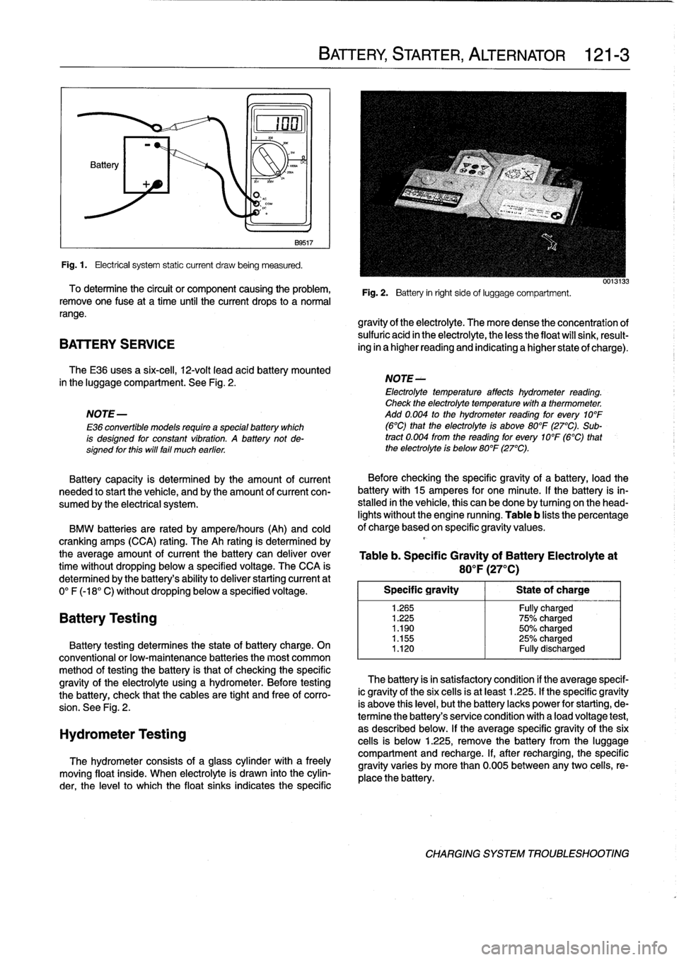
Fig
.1.
Electrical
system
static
current
draw
being
measured
.
To
determine
the
circuit
or
component
causing
the
problem,
remove
one
Puse
at
a
time
until
the
current
drops
to
a
normal
range
.
BATTERY
SERVICE
The
E36
uses
a
six-cell,
12-volt
leadacid
battery
mounted
in
the
luggage
compartment
.
See
Fig
.
2
.
NOTE-
E36
convertible
models
require
a
specialbattery
which
is
designed
for
constant
vibratfon
.
A
battery
not
de-signed
for
this
will
fail
much
earlier
.
Battery
capacity
is
determined
by
the
amount
of
current
needed
tostart
the
vehicle,
and
by
the
amount
of
current
con-
sumed
by
the
electrical
system
.
BMW
batteries
are
rated
by
ampere/hours
(Ah)
and
cold
cranking
amps
(CCA)
rating
.
The
Ah
rating
is
determined
by
the
average
amount
of
current
the
battery
can
deliver
over
time
without
dropping
below
a
specified
voltage
.
The
CCA
is
determined
by
the
battery's
ability
to
deliver
starting
current
at
0°
F
(-18°
C)
without
dropping
below
a
specified
voltage
.
Battery
Testing
noN~A
B9517
Battery
testing
determines
the
state
of
battery
charge
.
On
conventional
or
low-maintenance
batteries
the
most
common
method
of
testing
the
battery
is
that
of
checking
the
specific
gravity
of
the
electrolyte
using
a
hydrometer
.
Before
testing
the
battery,
check
that
the
cables
are
tight
and
free
of
corro-
sion
.
See
Fig
.
2
.
Hydrometer
Testing
The
hydrometer
consists
of
a
glass
cylinder
with
a
freely
moving
float
inside
.
When
electrolyte
is
drawn
into
the
cylin-
der,
the
levelto
which
the
float
sinks
indicates
the
specific
BATTERY,
STARTER,
ALTERNATOR
121-
3
Fig
.
2
.
Battery
in
right
sideof
luggage
compartment
.
gravity
of
the
electrolyte
.
The
more
dense
the
concentration
of
sulfuric
acid
in
the
electrolyte,
the
less
the
float
will
sink,
result-
ing
in
a
higher
reading
and
indicating
a
higher
state
of
charge)
.
NOTE-
Electrolyte
temperature
affects
hydrometer
reading
.
Check
the
electrolyte
temperaturewith
a
thermometer
.
Add
0
.004
to
the
hydrometer
reading
for
every
10°F
(6°C)
that
the
electrolyte
is
above
80°F
(27°C)
.
Sub-
tract
0
.004
from
the
reading
for
every
10°F
(6°C)
that
the
electrolyte
is
below
80°F
(27°C)
.
Before
checking
the
specificgravity
of
a
battery,
load
the
battery
with
15
amperes
for
one
minute
.
lf
the
battery
is
in-
stalled
in
the
vehicle,
this
can
be
done
by
turning
on
the
head-
lights
without
the
engine
running
.
Table
b
lists
the
percentage
of
charge
based
on
specific
gravity
values
.
Table
b
.
Specific
Gravity
of
Battery
Electrolyteat
80
°
F
(27°C)
Specific
gravity
1
Stateof
charge
1
.265
Fully
charged
1
.225
75%
charged
1
.190
50%
charged
1
.155
25%
charged
1
.120
Fully
discharged
The
battery
isin
satisfactory
condition
if
theaverage
specif-
ic
gravity
of
the
six
cells
is
at
least
1
.225
.
If
the
specific
gravity
is
above
this
leve¡,
butthe
battery
lacks
power
for
starting,
de-
termine
the
battery's
senrice
condition
with
a
load
voltage
test,
as
described
below
.
If
the
average
specific
gravity
of
the
six
cells
is
below
1
.225,
remove
the
battery
from
the
luggage
compartment
and
recharge
.
If,
after
recharging,
the
specific
gravity
varies
by
more
than
0
.005
between
any
two
celis,
re-
place
the
battery
.
CHARGING
SYSTEM
TROUBLESHOOTING
Page 140 of 759
121-
4
BATTERY,
STARTER,
ALTERNATOR
BatteryOpen-Circuit
Voltage
Test
Battery
Charging
Before
making
the
test,
load
the
battery
with
15
amperes
for
Discharged
batteries
can
be
recharged
using
a
battery
one
minute
with
a
batteryload-tester
or
turn
on
the
headlights
charger
.
The
battery
should
be
removed
from
the
luggage
for
about
one
minute
without
the
engine
running
.Then
discon-
compartment
during
charging
.
nect
the
battery
negative
(-)
cable
and
connect
a
digital
volt-
meter
acrossthe
battery
terminals
.
Open-circuit
voltage
Prolonged
charging
causes
electrolyte
evaporation
to
a
lev
levels
are
given
in
Table
c
.
el
that
can
damage
the
battery
.
Itis
bestto
use
a
low-current
charger
(6
amperes
or
less)
to
prevent
battery
damage
If
the
open-circuit
voltage
ís
OK
butthe
battery
still
lacks
caused
by
overheating
.
power
for
starting,
make
a
load
voltage
test
.
If
the
open-circuit
voltage
is
below
12
.4
volts,
recharge
the
battery
and
retest
.
WARNING
-
Hydrogen
gas
given
off
by
the
battery
duringcharg-
Table
c
.
Open-Circuit
Voltage
and
Battery
Charge
ing
is
explosive
.
Do
not
smoke
.
Keep
open
llames
away
from
the
top
of
the
battery,
and
prevent
elec
Open-circuit
voltage
State
of
charge
trical
sparks
by
turning
offthe
battery
charger
be-
12
.6
V
or
more
Fully
charged
fore
connecting
or
disconnecting
it
.
12
.4
V
1
75%
charged
12
.2
V
50%
charged
CAUTION-
12
.0
V
25%
charged
"
Battery
electrolyte
(sulfuric
acid)
can
damage
the
car
.
If
electrolyte
isspilled,
clean
the
area
11
.7
V
or
less
Fully
discharged
with
a
solution
of
baking
soda
and
water
.
Battery
Load
Voltage
Test
A
battery
load
tester
is
required
for
a
load
voltage
test
.
The
-
Always
disconnect
both
battery
cables
and
re-
test
is
made
by
applying
a
high
resistive
load
to
the
battery
ter-
move
battery
from
vehicle
during
battery
charg-
ing
.
Do
not
exceed
16
.5volts
at
the
battery
.
minals
and
then
measuring
battery
voltage
.
The
battery
should
be
fully
charged
for
the
most
accurate
results
.
The
battery
ca-
bles
mustbe
disconnected
before
making
the
test
.
If
the
volt-
ALTERNATOR
$ERVICE
age
is
below
that
listed
in
Table
d,
the
battery
should
be
replaced
.
WARNING
-
Always
wear
protective
goggles
and
clothing
when
performing
aload
test
.
Table
d
.
Battery
Load
Test-Minimum
Voltage
(apply
200
amp
load
for
15
seconds)
Ambient
temperature
Voltage
80°F
(27°C)
9
.6
V
60°F
(16°C)
9
.5
V
40°F
(4°C)
9
.3
V
20°F
(-7°C)
8
.9
V
0°F
(-18°C)
8
.5
V
ALTERNATOR
SERVICE
"
Always
allow
a
frozen
battery
to
thaw
before
at-
tempting
to
recharge
it
.
Before
checking
the
alternator
and
regulator,
make
sure
the
battery
is
fully
charged
and
capable
of
holding
acharge
.
Check
that
the
battery
terminals
are
clean
and
tight
and
the
al-
ternator
drive
belt
is
properly
tensioned
and
not
severely
worn
.
Charging
system,
checking
CAUTION-
Do
not
disconnect
the
battery
while
the
engine
is
running,
.
Damage
to
the
alternator
andlorengine
electronic
systems
may
result
.
1.
Turn
ignition
key
on
.
Check
that
the
chargewarning
lamp
comes
on
.
NOTE-
If
the
warning
light
does
not
come
on,
repair
any
wiring
or
bulb
faults
before
continuing
to
check
the
charging
system
.