battery BMW 325i 1998 E36 Owners Manual
[x] Cancel search | Manufacturer: BMW, Model Year: 1998, Model line: 325i, Model: BMW 325i 1998 E36Pages: 759
Page 267 of 759
320
Steering
and
Wheel
Alignment
GENERAL
...
.
.
.
...
.
....
.
.
.
.
.
.
.
.
.
...
.
.
320-1
Outer
tie
rod
end,
replacing
.
...
.
.
.
.
.
.
.
...
.
320-4
Tie
rod,
replacing
.
.
.
.
.
.
.
.......
.
.
.
.
.
...
.
320-5
STEERING
WHEEL
320-1
Steering
wheel,
removing
and
installing
.....
320-1
WHEEL
ALIGNMENT
.
.
.
.........
.
.....
.320-5
POWER
STEERING
SYSTEM
.
.
.
.
.
.
.....
320-2
Front
Toe-in
and
Toe
Difference
Angle
.
.
...
.
320-6
Power
steering
pump,
Rear
Toe-in
.
.
.
.
.
.
.
...
.
................
320-6
removing
and
installing
..
.
.
.
.
.
.
.
.
.
.....
320-2
Wheel
Alignment
Specifications
.....
.
......
320-6
Power
steering
system,
bleeding
and
filling
.
.
320-3
STEERING
GEAR
.
.
.
.
...
.
.
.
.
.
.
.
.
.
.....
320-3
Steering
gear
rack,
removing
and
installing
.
...
.
..
.
..
..
..
.
..
.
320-3
GENERAL
STEERING
WHEEL
This
repair
group
covers
servicing
of
the
mechanical
and
The
BMW
E36
is
equipped
with
an
SRS
airbag
mounted
in
hydraulic
components
of
the
steering
system,
including
wheel
the
steering
wheel
.
Improper
handling
of
the
airbag
could
alignment
information
.
cause
serious
injury
.
The
airbag
is
an
explosivedevice
and
should
be
treated
with
extreme
caution
.
Always
follow
the
air-
The
variable-assist
power
steering
system
consistsof
an
bag
removal
procedure
as
outlined
in
721
Airbag
System
engine-driven
hydraulic
pump,
a
rack-and-pinion
steering
(SRS)
.
gear
assembly
with
an
integral
hydraulic
control
valve,
and
connecting
linkage
to
the
road
wheels
.
WARNING-
"
The
BMW
Supplemental
Restraint
System
(SRS)
At
lowspeeds,
maximum
power
assist
is
provided
to
ease
is
complex
and
special
precautions
must
be
ob-
parking
and
city
driving
.
At
high
speeds,
assist
is
reduced
to
served
when
servicing
.
Serious
injury
may
result
ensure
stability
.
The
power
steering
system
varies
assist
if
system
service
is
attempted
by
persons
unfa-
based
on
engine
speed
.
miliar
with
the
BMW
SRS
and
its
approved
ser-
vice
procedures
.
BMW
specifies
that
all
ING-
inspection
and
service
shouldbe
performed
by
WARN
an
authorized
BMW
dealer
.
"
Do
not
reuse
self-locking
nuts
.
They
are
de-signed
to
beused
only
once
and
may
failif
re-
"
BMW
Supplemental
Restraint
Systems
(SRS)
used
.
Always
replace
them
with
new
locking
nuts
.
are
equipped
with
a
back-up
power
supply
inside
the
SRS
control
module
.
A
10minute
waiting
"
Do
not
ínstall
bolts
and
nuts
coated
with
under-
shouldbe
observed
after
the
battery
cable
has
coating
wax,
as
correct
tightening
torque
cannot
been
disconnected
.
This
will
allow
the
reserve
be
assured
.
Always
clean
the
threads
with
sol-
power
supply
to
discharge
.
vent
before
installation,
or
install
new
parts
.
"
Do
not
attempt
to
weldor
straighten
any
steering
components
.
Always
replace
damaged
parts
.
NOTE-
For
information
on
steering
column-mounted
switches
and
the
ignition
lock,
see
612
Switches
and
Electrical
Accessories
.
STEERING
AND
WHEEL
ALIGNMENT
320-1
Caster
and
Camber
.
.
.
.
.
...........
.
....
320-5
TABLES
a
.
Front
Wheel
Alignment
Specifications
.
...
.......
320-6
b
.
Rear
Wheel
Alignment
Specifications
.
...
.......
320-6
Steering
wheel,
removing
and
installing
1
.
Center
steering
wheel
.
Make
sure
front
wheelsare
pointed
straight
ahead
.
2
.
Disconnect
negative
(-)
cable
from
battery
and
cover
terminal
with
insulating
material
.
CAUTION-
Prior
to
disconnectiog
the
battery,
read
the
battery
disconnection
cautions
given
at
the
front
of
this
manual
on
page
viii
.
STEERING
WHEEL
Page 269 of 759
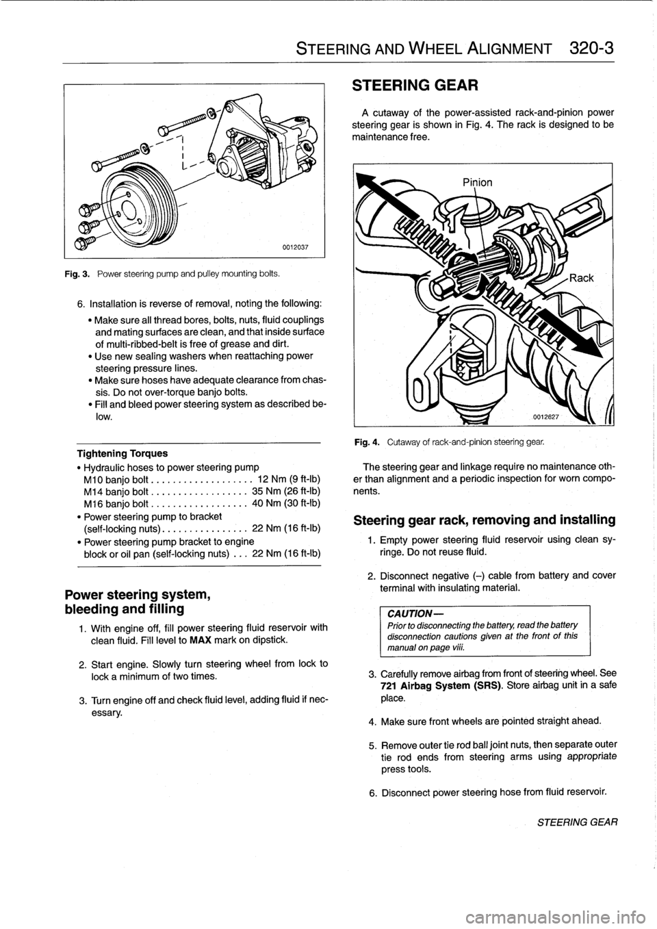
Fig
.
3
.
Power
steering
pump
and
pulley
mounting
bolts
.
6
.
Installation
is
reverse
of
removal,
noting
the
following
:
"
Make
sure
al¡
thread
bores,
bolts,
nuts,
fluid
couplings
and
mating
surfaces
are
clean,
and
that
inside
surface
of
multi-ribbed-belt
is
free
of
grease
and
dirt
.
"
Use
new
sealing
washers
when
reattaching
power
steering
pressure
lines
.
"
Make
sure
hoses
have
adequate
clearance
from
chas-
sis
.
Do
not
over-torque
banjo
bolts
.
"
Fill
and
bleed
power
steering
system
as
described
be-
low
.
Power
steering
system,
bleeding
and
filling
1
.
Wíth
engine
off,
fill
power
steering
fluid
reservoir
with
clean
fluid
.
Fill
levelto
MAX
mark
on
dipstick
.
STEERING
AND
WHEEL
ALIGNMENT
320-
3
STEERING
GEAR
A
cutaway
of
the
power-assisted
rack-and-pinion
power
steering
gear
is
shown
in
Fig
.
4
.
The
rack
is
designed
to
be
maintenance
free
.
Pinion
Fig
.
4
.
Cutaway
of
rack-and-pinion
steering
gear
.
Tightening
Torques
"
Hydraulic
hoses
to
power
steering
pump
?he
steering
gear
and
linkage
require
no
maintenance
oth-
M10
banjo
bolt
.........
..
.
...
...
.
12
Nm
(9
ft-Ib)
er
than
alignment
and
a
periodic
inspection
for
worn
compo
M14
banjo
bolt
..............
..
..
35
Nm
(26
ft-Ib)
nents
.
M16
banjo
bolt
..............
...
.
40
Nm
(30
ft-Ib)
"
Power
steering
pump
to
bracket
Steering
gear
rack,
removing
and
installing
(self-locking
nuts)
.............
..
.
22
Nm
(16
ft-Ib)
"
Power
steering
pump
bracket
to
engine
1
.
Empty
power
steering
fluid
reservoir
using
clean
sy-
block
or
oil
pan
(self-locking
nuts)
...
22
Nm
(16
ft-lb)
ringe
.
Do
not
reuse
fluid
.
2
.
Disconnect
negative
(-)
cable
from
battery
and
cover
terminal
with
insulating
material
.
CAUTION-
Prior
to
disconnectiog
the
battery,
read
the
battery
disconnection
cautions
given
at
the
front
of
this
manual
on
page
viii
.
2
.
Start
engine
.
Slowly
turn
steering
wheelfrom
lock
to
lock
a
minimum
of
two
times
.
3
.
Carefully
remove
airbag
from
frontof
steering
wheel
.
See
721
Airbag
System
(SRS)
.
Store
airbag
unit
in
a
sale
3
.
Turn
engine
off
and
check
fluid
leve¡,
adding
fluid
if
nec-
place
.
essary
.
4
.
Make
sure
front
wheelsare
pointed
straight
ahead
.
5
.
Remove
outer
tie
rod
ball
joínt
nuts,
thenseparate
outer
tie
rod
ends
from
steering
arms
using
appropriate
press
tools
.
6
.
Disconnect
power
steering
hose
from
fluid
reservoir
.
STEERING
GEAR
Page 298 of 759
340-
8
BRAKES
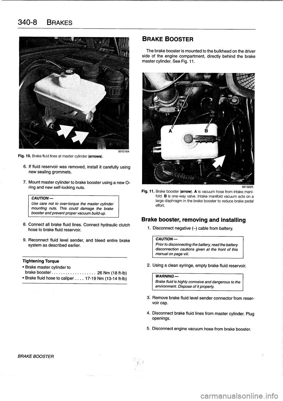
Fig
.
10
.
Brake
fluid
linesat
master
cylinder
(arrows)
.
6
.
If
fluid
reservoir
was
removed,
install
it
carefully
using
new
sealing
grommets
.
7
.
Mount
master
cylinder
to
brake
booster
using
a
new
0-
ring
and
new
self-locking
nuts
.
CAUTION-
Use
cave
not
to
over-torque
the
master
cylinder
mounting
nuts
.
This
could
damage
the
brake
booster
and
prevent
proper
vacuum
build-up
.
0012164
8
.
Connect
all
brake
fluid
lines
.
Connect
hydraulic
clutch
hose
to
brake
fluid
reservoir
.
9
.
Reconnect
fluid
leve¡
sender,
and
bleed
entire
brake
systemas
described
earlier
.
BRAKE
BOOSTER
BRAKE
BOOSTER
The
brake
booster
is
mounted
to
the
bulkhead
on
the
driver
sideofthe
engine
compartment,
directly
behind
the
brake
master
cylinder
.
See
Fig
.
11
.
0015225
Fig
.
11
.
Brake
booster
(arrow)
.
A
is
vacuum
hose
from
intake
mani-
fold
.
B
is
one-way
valve
.
Intake
manifold
vacuum
acts
ona
large
diaphragm
in
the
brake
booster
to
reducebrake
pedal
effort
.
Brake
booster,
removing
and
installing
1
.
Disconnect
negative
(-)
cable
from
battery
.
CAUTION-
Prior
to
disconnecting
the
battery,
read
the
battery
disconnection
cautions
given
at
the
front
of
this
manual
onpage
vi¡¡
.
Tightening
Torque
"
Brake
master
cylinder
to
2
.
Using
a
clean
syringe,
empty
brake
(luid
reservoir
.
brake
booster
.....
..
.
..
.........
26
Nm
(18
ft-Ib)
WARNING-
"
Brake
fluid
hose
to
caliper
....
17-19
Nm
(13-14
ft-Ib)
Brake
fluid
is
highly
corroslve
and
dangerous
to
the
environment
.
Dispose
of
it
properly
.
3
.
Remove
brake
fluid
level
sender
connector
from
reser-
voir
cap
.
4
.
Disconnectbrake
fluid
lines
from
master
cylinder
.
Plug
openings
.
5
.
Disconnect
engine
vacuum
hose
from
brake
booster
.
Page 303 of 759
GENERAL
.
....
.
.
.
.
.
.......
.
.
.
.
.
...
.
.
.
400-1
INTERIOR
EQUIPMENT
......
.
.
.
.......
400-4
Seats
and
Seatbelts
.
.
.
.
.
.
.....
.
.
.
.
.
..
.
..
400-4
BODY
ASSEMBLY
.
.
.
.
.
.....
.
.
.
.
.
.
.
.
.
.
.400-2
Instruments
and
Controls
.
..
....
.
.
.
.
.
.
.
...
400-4
Exterior
and
Aerodynamics
....
.
.
.
.
.
.
.
.
.
.
.
400-2
Central
Body
Electronics
.......
.
.
.
...
.
...
400-5
Coupe
Models
..
.
.
.
.
.
.......
.
.
.
.
.
.
.
.
.
..
400-3
Electronic
Immobilization
System
.
.
.
...
.
...
400-5
Convertible
Models
.
.
.
.
.
.
.
.....
.
.
.
.
.
.
.
..
400-3
Heating
and
Air
Conditioning
.
...
.
.
.
.
.
.
.
...
400-6
GENERAL
This
section
covers
system
descriptions
and
general
ser-
vice
information
for
the
repair
groupsfound
in
4
Body
and
5
Body
Equipment
.
When
working
or
servicing
cars
equipped
with
SRS
air-
bag(s),
the
following
precautions
must
be
observed
to
prevent
injury
.
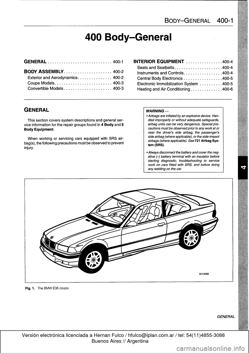
F19
.1
.
The
BMW
E36
coupe
.
400
Body-General
BODY-GENERAL
400-1
WARNING
-
"
Airbags
are
inflated
by
an
explosivedevice
.
Han-dled
improperly
or
without
adequate
safeguards,
airbag
units
can
be
very
dangerous
.
Special
pre-cautions
must
be
observed
prior
to
any
work
ator
near
the
driver's
side
airbag,
the
passenger's
side
airbag
(where
applicable),
or
the
side-impact
aírbags
(where
applicable)
.
See
721
Airbag
Sys-
tem
(SRS)
.
"
Always
disconnect
the
battery
and
cover
the
neg-
ative
(-)
battery
terminalwith
an
insulator
before
starting
diagnostic,
troubleshooting
or
service
work
oncars
fitted
with
SRS,
and
before
doíng
any
welding
on
the
car
.
0013098
GENERAL
Page 305 of 759
TheE36
convertible
is
an
all-season
vehicle
with
a
high
lev-
e¡offunctionality,
excellent
interior
comfort,
and
acoustic
re-
finement
.
Interior
materials
and
colors,
the
soft
top
and
the
light-alloy
wheelshave
been
carefully
matched
.
Various
versions
of
manual
and
automatic
soft
tops
have
been
used,
with
the
fully
automatic
convertible
roof
being
in-
stalled
beginning
in
the
1997
model
year
.
A
hard-top
in
body
color
with
heated
rear
window
is
avail-
ableas
an
option
for
the
cold
season
.
BODY-GENERAL
400-
3
Coupe
Models
The
convertible
body
structure
includes
many
passive
safe-
ty
refinements
over
its
fixed-top
counterparts
.
Some
of
the
en-
TheE36
coupe
is
similar
to
the4-door
sedan,
but
has
a
hancements
include
:
more
stretched
and
sleeker
appearance
.
Thus,
with
the
same
wheelbase
and
identicallength,
it
looks
different
but
still
famil-
"
More
rígíd
underbody
.
iar
.
"
Transverse
seat
members
.
"
Reinforced
windshield
frame
with
bonded
windshield,
The
2-door
variant
differs
from
the
4-door
sedan
by
a
3
.12
and
tubular
door
reinforcements
.
inch
(8
cm)
longer
front
end,
a
flatter
hood
line
with
air
slits,
"
Rollover
protection
system,
which
is
tripped
into
position
and
a
roof
almost
1
.2
inches
(3
cm)
shorter
.
Additional
differ-
in
a
fraction
of
second
.
This
is
available
as
optional
ences
include
wider
doors
with
frameless
Windows,
glass-
equipment
(standard
on
the
1998
328iC)
and
may
be
fit-
covered
door-posts
(B-pillars)
and
a
shorter
and
lower
lug-
ted
to
earlier
convertible
models
.
With
this
feature,
two
gage
compartment
lid
.
bars
fully
independent
of
each
other
come
up
behind
each
rear-seat
backrest
when
the
vehicle
is
in
danger
of
Convertible
Models
turning
over
.
A
convertible
body
normally
flexes
and
vibrates,
transfer-
ring
oscillations
to
the
luggage
compartment
.
In
the
E36
con-
vertible,
BMW
utilizes
a
special
battery
in
the
luggage
compartment,
in
conjunction
with
a
unique
battery
tray,
asa
vibration
dampening
system
to
counteract
thisoscillation
.
CAUTION
-
The
E36
convertible
requires
a
specialbattery
which
is
designed
for
constant
vibration
.
Information
for
the
convertible
top
and
its
related
mecha-
nisms
can
be
found
541
Convertible
Top
.
BODYASSEMBLY
Page 315 of 759
GENERAL
This
repair
group
covers
front
and
rear
door
repair
informa-
tion,
including
removal
and
installationof
the
interior
doorpan-
els
.
DOORS
WARNING
-
Late
M3
moddis
havealuminum
doors
.
Use
extra
care
in
handling
aluminum
parts
in
order
to
avoid
damage
from
gouging
or
corrosión
.
NOTE-
"
For
information
on
the
power
door
windows
and
door
glass
replacement,
sea512Door
Windows
.
"
Forinformation
on
the
power
door
locking
system,
see
515
Central
Locking
and
Anti-Theft
.
WARNING
-
Some
1997
and
all
1998
cars
are
fitted
with
side-im-
pact
airbags
in
the
front
doors
.
When
servicing
doors
on
cars
with
front
side-impact
airbags,
always
dis-
connect
the
negative
(-)
battery
terminal
.
See
721
Airbag
System
(SRS)
for
cautions
and
procedures
relating
to
the
airbag
system
.
Front
orrear
door,
removing
and
installing
1
.
If
workingon
front
door
with
side-impact
airbag,
discon-
nect
negative
(-)
battery
cable
.
CAUTION
-
Prior
to
disconnectiog
the
battery,
read
the
battery
disconnection
cautions
given
at
the
front
of
this
manual
on
page
vüi
.
2
.
Unbolt
main
harness
connector
at
door
pillar
and
sep-
arate
connector
.
See
Fig
.
1
.
411
Doors
GENERAL
.............
.
.
.
.
.
.
.
.
.
.
.
.
.
..
411-1
DOOR
PANELS
.
.
.
.
.
.
.
...
.
.
.
.
.
.
.
.
.
...
.
.
411-4
Front
door
trim
panel,
removing
and
installing
.411-4
DOORS
..
.
.
.
.
.
.
.
.
.
...
.
.......
.
....
.
.
.
411-1
Rear
door
trim
panel,
removing
and
installing
.411-5
Front
or
reardoor,
removing
and
installing
..
.
411-1
Rear
side
trim
panel,
removing
and
installing
Door
check,
replacing
.
.
.
.
.
.
.
.
.
.
.
.
.......
411-3
(coupemodel)
.
.
.
.
.
.
....
.
.............
411-6
Door
Adjustment
.......
.
.
.
.
.
.
.
.
.
.
.
.....
411-3
Rear
side
trim
panel,
removing
and
installing
(convertible
models)
.
...
.
.
.
.
.
.
.
.
.
.
.
...
.
411-6
DOORS
411-1
Fig
.
1
.
Door
harness
connector
being
removed
fromdoor
pillar
.
Re-
move
mountingscrews
atA,
then
separate
connector
by
pulling
upon
harness
lock(top
arrow)
.
3
.
Withdoor
fully
open,
remove
pin
bolts
from
top
and
bot-
tom
door
hinges
.
See
Fig
.
2
.
0011650
Fig
.
2
.
Door
hinge
pin
bolt
(arrow)
.
Top
hinge
shown
.
Also
remove
pin
bolt
from
lowerhinge
.
DOORS
Page 316 of 759
411-2
DOORS
4
.
Remove
retainer
clip
(early
models
only)
from
doorcheck
pin
onbody
pillar
.
Drive
out
door
check
pin
.
See
Fig
.
3
.
Door
Adjustment
"
Door
gap
to
fender/rear
door
.........
approx
.
5
mm
(0
.189
in)
"
Permíssible
deviation
from
parallel
.
.0
.5
mm
(0
.020
in)
0011651
Fig
.
3
.
Door
check
pin
being
removed
.
Note
retainer
clip
(A)
usedon
early
models
.
5
.
Remove
doorby
lifting
up
off
lowerhinge
halves
.
CAUTION-
Be
careful
not
to
damage
door
or
other
painted
body
surfaces
.
Make
sure
no
load
is
placedon
wiring
harness
.
6
.
Installation
is
reverse
of
removal
.
Keep
in
mind
the
fol-
lowing
:
"
Align
doorso
that
panel
gaps
are
equal
on
either
side,
as
described
later
.
If
necessary,
adjust
door
hinges
as
described
later
.
"
Adjust
door
striker
so
that
trailing
edge
of
front
door
is
slightly
higher
(1
mm)
than
leading
edge
of
rear
door
.
See
515
Central
Locking
and
Anti-Theft
.
"
Repair
any
paint
damage
and
paínt
any
exposed
met-
al
.
CAUTION-
.
"In
2-door
models,
removing
and
installing
the
door
may
upset
the
adjustment
and
alignment
of
the
window
.
Window
adjustment,
as
described
in
512DoorWindows,
must
be
carried
out
ater
installation
to
prevent
damaging
the
glass
.
"
If
battery
power
is
lost
or
the
battery
has
been
disconnected,
the
windows
must
be
re-initialized
.
Both
one
touch
upldown
and
pinch-protection
will
be
inactive
until
windows
are
re-initialized
.
See
512
Door
Windows
.
DOOR
CHECK,
REPLACING
Door
check,replacing
WARNING
-
Some
1997
and
all
1998
cars
are
fitted
with
side-im-
pact
airbags
in
the
front
doors
.
When
servicing
doors
on
cars
with
front
side-impact
airbags,
always
dis-
connect
the
negative
(-)
battery
terminal
.
See
721
Al
rbag
System
(SRS)
for
cautions
and
procedures
relating
to
the
airbag
system
.
1
.
Closedoor
window
completely
.
2
.
If
working
on
front
door
with
side-impact
airbag,
discon-
nect
negative
(-)
battery
cable
.,
CAUTION-
Prior
to
disconnectiog
the
battery,
read
the
battery
disconnection
cautions
gíven
at
the
front
of
this
manual
on
page
viii
.
3
.
Remove
interior
door
panel
and
vapor
barrier
as
de-
scribed
later
.
4
.
Where
applicable,
remove
side-impact
airbag
from
door
.
See
721
Airbag
System
(SRS)
.
NOTE-
In
some
models
covered
inthis
manual,
ít
is
not
essen-
tial
to
remove
the
side-ímpact
airbag
to
access
internal
door
components
.
However,
the
procedure
is
recom-
mended
for
safety
reasons
.
5
.
Remove
retainer
clip
(early
models
only)
from
door
check
pin
on
body
pillar
.
Drive
out
door
check
pin
.
Refer
to
Fig
.
3
.
6
.
Remove
bolts
and
rubber
cover
fromdoor
check
lock-
plate
ondoor
.
7
.
Remove
door
check
from
inside
door
.
8
.
Installation
is
reverse
of
removal
.
"
Lubricate
door
check
before
installing
.
"
Use
new
mounting
bolts
when
reinstalling
the
side-im-
pact
airbag
to
thedoor(where
applicable)
.
"
If
battery
was
disconnected,
re-initialize
window
regu-
lator
motors
as
described
in
512
Door
Windows
.
Page 317 of 759
Door
Hinge
Adjustment
If
the
installed
door
is
uneven
or
out
of
parallel,
shims
can
be
used
to
correct
its
position
.
The
shims
are
placedbehind
the
hinge
plate
and
are
available
in
two
different
thicknesses
(0
.5
mm
and
1
.0
mm)
.
See
Fig
.
4
.
Tightening
Torque
"
Door
hinge
to
door
.............
..
21
Nm
(15
.5
ft-I
b)
"
Door
striker
to
door
...........
...
25
Nm
(18
ft-Ib)
DOOR
PANELS
0
l
o
0013102
Fig
.
4
.
Door
hinge
and
door
check
components
.
Front
and
rear
doors
are
similar
.
WARNING
-
Some
1997
and
all
1998
cars
are
fitted
with
side-im-
pact
airbags
in
the
front
doors
.
When
servicing
doors
on
cars
with
front
side-impact
airbags,
always
dis-
connect
the
negative
()
battery
terminal
.
See
721
Airbag
System
(SRS)
for
cautions
and
procedures
relating
to
the
airbag
system
.
Front
door
trimpanel,
removing
and
in-
stalling
1
.
On
cars
with
side-impact
airbags,
disconnect
negative
(-)
battery
cable
.
CAUTION
-
Prior
to
disconnecting
the
battery,
read
the
battery
disconnection
cautions
given
at
the
front
of
this
manual
on
page
viii
.
Fig
.
5
.
Pry
outside
mirror
switch
from
door
armrest
.
3
.
Unscrew
door
locking
knob
.
Fig
.
6
.
Pry
off
plugs
(arrows)
and
remove
screws
.
DOORS
411-
3
2
.
Carefully
pry
out
mirror
adjustment
switch
and
discon-
nect
harness
connector
from
switch
.
Fig
.
5
.
5
.
Unclip
door
panel
from
door
perimeter
.
See
Fig
.
7
.
0013168
4
.
Pry
off
trim
cover
for
insíde
door
handle
.
Pry
off
con-
cealing
plugs
from
armrest
.
Remove
door
panel
retain-
ing
screws
.
See
Fig
.
6
.
UU13169
DOOR
PANELS
Page 318 of 759
411-
4
DOORS
6
.
Disconnect
radio
speaker
harness
connector
.
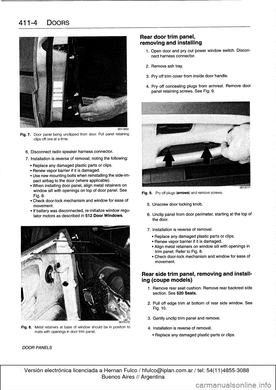
Fig
.
7
.
Door
panel
being
unclipped
from
door
.
Pull
panel
retaining
clips
off
one
at
a
time
.
7
.
Installation
is
reverse
of
removal,
noting
the
following
:
"
Replace
any
damaged
plastic
parts
orclips
.
"
Renew
vapor
barrier
ifit
is
damaged
.
"
Use
new
mounting
bolts
when
reinstalling
the
side-im-
pactairbag
to
the
door
(where
applicable)
.
"
When
installing
door
panel,
align
metal
retainers
on
window
sill
with
openingsontop
of
door
panel
.
See
Fig
.
8
.
"
Check
door-lock
mechanism
and
window
for
ease
of
movement
.
"
If
battery
was
disconnected,
re-initialize
window
regu-
lator
motors
as
described
in
512
Door
Windows
.
373
Fig
.
8
.
Metal
retainers
at
base
of
window
should
be
in
position
to
mate
with
openings
in
door
trim
panel
.
DOOR
PANELS
Reardoor
trimpanel,
removing
and
installing
1
.
Open
door
and
pry
out
power
window
switch
.
Discon-
nect
harness
connector
.
2
.
Remove
ash
tray
.
3
.
Pry
off
trim
cover
from
inside
door
handle
.
4
.
Pry
off
concealing
plugs
from
armrest
.
Remove
door
panel
retaining
screws
.
See
Fig
.
9
.
Fig
.
9
.
Pry
off
plugs
(arrows)
andremove
screws
.
5
.
Unscrew
door
locking
knob
.
6
.
Unclip
panel
from
door
perimeter,
starting
at
thetop
of
the
door
.
7
.
Installation
is
reverse
of
removal
.
"
Replace
any
damaged
plastic
parts
or
clips
.
"
Renew
vapor
barrier
ifit
is
damaged
.
"
Align
metal
retainers
on
window
sill
with
openings
in
trim
panel
.
Refer
to
Fig
.
8
.
"
Check
door-lock
mechanism
and
window
for
ease
of
movement
.
Rear
side
trim
panel,
removing
and
install-
ing
(coupe
models)
1
.
Remove
rear
seat
cushion
.
Remove
rear
backrest
side
section
.
See
520
Seats
.
2
.
Pull
off
edge
trimat
bottom
of
rear
side
window
.
See
Fig
.
10
.
3
.
Gently
unclip
trim
panel
andremove
.
4
.
Installation
is
reverse
of
removal
.
"
Replace
any
damaged
plastic
parts
or
clips
.
Page 328 of 759
510-
6
EXTERIOR
TRIM,
BUMPERS
Rear
bumper
impact
absorber,replacing
1
.
Remove
bumperas
described
above
.
2
.
Remove
luggage
compartment
floor
covering
.
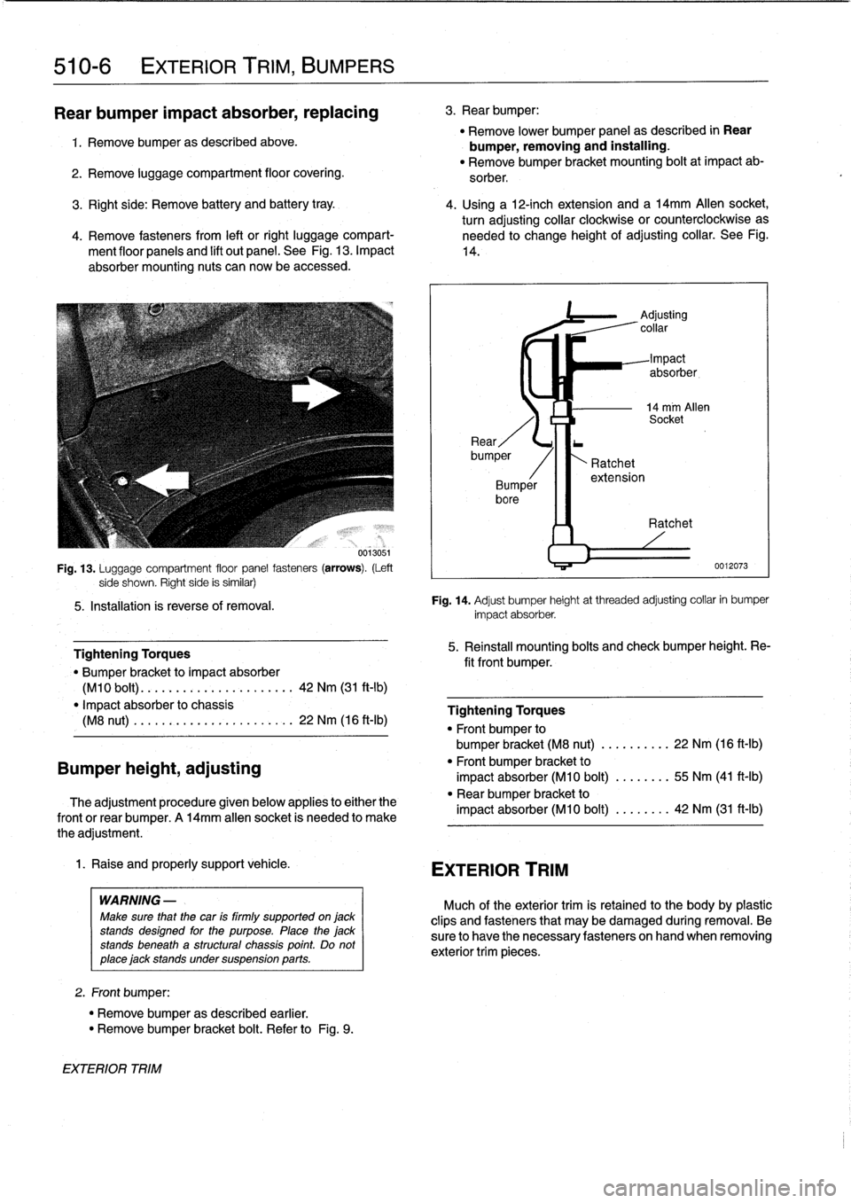
Fig
.
13
.
Luggage
compartment
floor
panel
fasteners
(arrows)
.
(Left
side
shown
.
Righf
side
is
similar)
5
.
Installation
ís
reverse
of
removal
.
Bumper
height,
adjusting
Tightening
Torques
"
Bumper
bracket
to
impact
absorber
(M10
bolt)
.
............
.
...
..
..
.
42
Nm
(31
ft-lb)
"
Impact
absorber
to
chassis
(M8
nut)
.
.
..........
.
......
.
.
.
.
22
Nm
(16
ft-Ib)
The
adjustment
procedure
given
below
applies
to
either
the
frontor
rear
bumper
.
A
14mm
allen
socket
is
needed
to
make
the
adjustment
.
1
.
Raise
and
properly
support
vehicle
.
WARNING
-
Make
sure
that
the
car
is
firmly
supported
on
jack
stands
designed
for
the
purpose
.
Place
the
jack
stands
beneath
a
structural
chassis
point
.
Do
not
place
jack
stands
under
suspension
parts
.
2
.
Front
bumper
:
"
Remove
bumper
as
described
earlier
.
"
Remove
bumper
bracket
bolt
.
Refer
to
Fig
.
9
.
EXTERIOR
TRIM
3
.
Rear
bumper
:
"
Remove
lower
bumper
panel
as
described
in
Rear
bumper,
removing
and
installing
.
"
Remove
bumper
bracket
mounting
bolt
at
impact
ab-
sorber
.
3
.
Right
side
:
Remove
battery
and
battery
tray
.
4
.
Using
a
12-inch
extension
and
a
l4mm
Allen
socket,
turn
adjusting
collar
clockwise
or
counterclockwise
as
4
.
Remove
fasteners
from
left
or
right
luggage
compart-
needed
to
change
height
of
adjusting
collar
.
See
Fig
.
ment
floor
panels
and
lift
out
panel
.
See
Fig
.
13
.
Impact
14
.
absorber
mounting
nuts
can
now
be
accessed
.
~4
EXTERIOR
TRIM
Ratchet
extension
Adjusting
collar
Impact
absorber,
14
mm
Allen
Socket
Ratchet
0012073
Fig
.
14
.
Adjust
bumper
height
at
threaded
adjusting
collar
in
bumper
impact
absorber
.
5
.
Reinstall
mounting
bolts
and
check
bumper
height
.
Re-
fit
front
bumper
.
Tightening
Torques
"
Front
bumper
to
bumper
bracket
(M8
nut)
......
.
..
.
22
Nm
(16
ft-Ib)
"
Front
bumper
bracket
to
impact
absorber
(M10
bolt)
........
55
Nm
(41
ft-Ib)
"
Rear
bumper
bracket
to
impact
absorber
(M10
bolt)
........
42
Nm
(31
ft-Ib)
Much
of
the
exteriortrim
is
retained
to
the
body
by
plasticclips
and
fasteners
that
may
be
damaged
during
removal
.
Be
sure
to
have
the
necessary
fasteners
onhand
when
removing
exterior
trim
pieces
.